$46
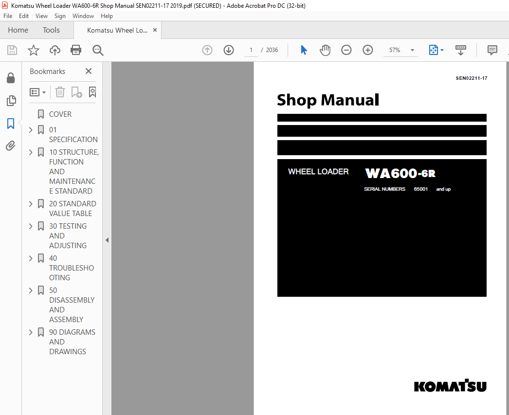
Komatsu WA600-6R Wheel Loader Shop Manual SEN02211-17 – PDF DOWNLOAD
Komatsu WA600-6R Wheel Loader Shop Manual SEN02211-17 – PDF DOWNLOAD
FILE DETAILS:
Komatsu WA600-6R Wheel Loader Shop Manual SEN02211-17 – PDF DOWNLOAD
Language : English
Pages : 2036
Downloadable : Yes
File Type : PDF
Size: 120 MB
DESCRIPTION:
Komatsu WA600-6R Wheel Loader Shop Manual SEN02211-17 – PDF DOWNLOAD
SERIAL NUMBERS 65001 and up
How to read the shop manual :
1. Composition of shop manual:
This shop manual contains the necessary technical information for services performed in a workshop.
For ease of understanding, the manual is divided into the following sections.
00. Index and foreword
This section explains the shop manuals list, table of contents, safety, and basic information.
01. Specification
This section explains the specifications of the machine.
10. Structure, function and maintenance standard
This section explains the structure, function, and maintenance standard values of each component.
The structure and function sub-section explains the structure and function of each component. It
serves not only to give an understanding of the structure, but also serves as reference material for
troubleshooting. The maintenance standard sub-section explains the criteria and remedies for disassembly
and service.
20. Standard value table
This section explains the standard values for new machine and judgement criteria for testing,
adjusting, and troubleshooting. This standard value table is used to check the standard values in
testing and adjusting and to judge parts in troubleshooting.
30. Testing and adjusting
This section explains measuring instruments and measuring methods for testing and adjusting, and
method of adjusting each part. The standard values and judgement criteria for testing and adjusting
are explained in Testing and adjusting.
40. Troubleshooting
This section explains how to find out failed parts and how to repair them. The troubleshooting is
divided by failure modes. The “S mode” of the troubleshooting related to the engine may be also
explained in the Chassis volume and Engine volume. In this case, see the Chassis volume.
50. Disassembly and assembly
This section explains the special tools and procedures for removing, installing, disassembling, and
assembling each component, as well as precautions for them. In addition, tightening torque and
quantity and weight of coating material, oil, grease, and coolant necessary for the work are also
explained.
90. Diagrams and drawings (chassis volume)/Repair and replacement of parts (engine volume)
q Chassis volume
This section gives hydraulic circuit diagrams and electrical circuit diagrams.
q Engine volume
This section explains the method of reproducing, repairing, and replacing parts.
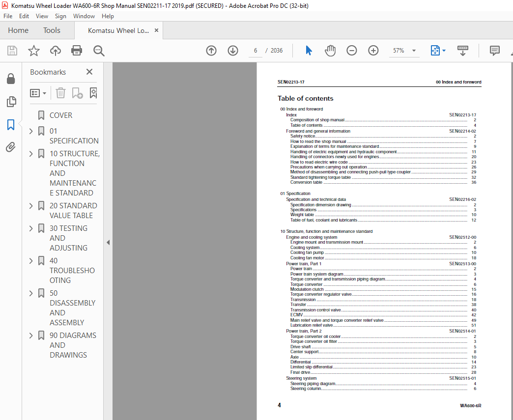
TABLE OF CONTENTS:
Komatsu WA600-6R Wheel Loader Shop Manual SEN02211-17 – PDF DOWNLOAD
00 Index and foreword
Index SEN02213-17
Composition of shop manual 2
Table of contents 4
Foreword and general information SEN02214-02
Safety notice 2
How to read the shop manual 7
Explanation of terms for maintenance standard 9
Handling of electric equipment and hydraulic component 11
Handling of connectors newly used for engines 20
How to read electric wire code 23
Precautions when carrying out operation 26
Method of disassembling and connecting push-pull type coupler 29
Standard tightening torque table 32
Conversion table 36
01 Specification
Specification and technical data SEN02216-02
Specification dimension drawing 2
Specifications 3
Weight table 10
Table of fuel, coolant and lubricants 12
10 Structure, function and maintenance standard
Engine and cooling system SEN02512-00
Engine mount and transmission mount 2
Cooling system 6
Cooling fan pump 10
Cooling fan motor 18
Power train, Part 1 SEN02513-00
Power train 2
Power train system diagram 3
Torque converter and transmission piping diagram 4
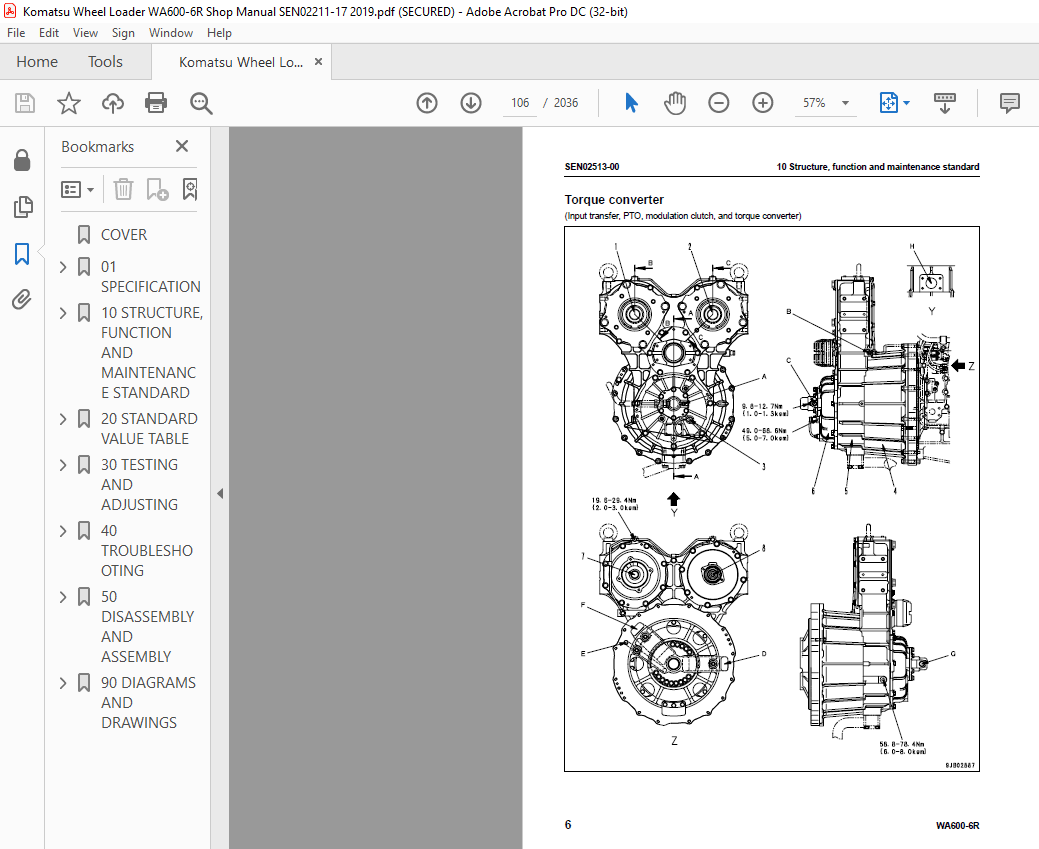
Torque converter 6
Modulation clutch 15
Torque converter regulator valve 16
Transmission 18
Transfer 38
Transmission control valve 40
ECMV 42
Main relief valve and torque converter relief valve 49
Lubrication relief valve 51
Power train, Part 2 SEN02514-01
Torque converter oil cooler 2
Torque converter oil filter 3
Drive shaft 5
Center support 8
Axle 10
Differential 14
Limited slip differential 23
Final drive 28
Steering system SEN02515-01
Steering piping diagram 4
Steering column 6
00 Index and foreword SEN02213-17
WA600-6R 5
Joystick steering lever linkage 7
Joystick EPC valve 8
Lock valve 9
Steering valve 10
Rotary valve 13
Steering control valve 16
Two-way restrictor valve 32
Stop valve 33
Steering pump 34
Steering cylinder 48
Emergency steering piping diagram 50
Diverter valve 51
Emergency steering pump 59
Brake system SEN02516-02
Brake piping diagram 2
Brake 4
Brake valve 8
Accumulator charge valve 16
EPC relief valve 22
Accumulator (for brake) 24
Slack adjuster 26
Parking brake 30
Parking brake solenoid valve 32
Emergency parking brake release valve 34
Brake cooling pump 35
Undercarriage and frame SEN02517-00
Axle mount 2
Center hinge pin 7
Hydraulic system, Part 1 SEN02518-00
Hydraulic piping diagram 2
Work equipment control lever linkage 4
Hydraulic tank 6
Work equipment hydraulic pump 8
Hydraulic system, Part 2 SEN02519-01
Control valve 2
CLSS 16
Each function and operation of each valve 21
Accumulator (for PPC circuit) 40
Accumulator (for ECSS) 41
Triple pump 42
Work equipment SEN02520-02
Work equipment linkage 2
Bucket 6
Bucket positioner and boom kick-out 10
Work equipment lubrication 12
Work equipment cylinder 14
Cab and its attachments SEN02521-00
ROPS cab 2
Air conditioner 4
Electrical system, Part 1 SEN02522-02
Machine monitor system 2
Machine monitor 8
Electrical system, Part 2 SEN02523-00
Work equipment control system 2
Transmission controller system 38
Electrical system, Part 3 SEN02524-02
Electric transmission control 2
SEN02213-17 00 Index and foreword
6 WA600-6R
Engine starting/stopping circuit 4
Parking brake circuit 7
Sensor 11
VHMS controller related 34
VHMS controller and wireless LAN system 35
Work equipment electric lever 41
20 Standard value table
Standard service value table SEN02580-05
Standard service value table for engine 2
Standard service value table for chassis 3
30 Testing and adjusting
Testing and adjusting, Part 1 SEN02581-05
Tools for testing, adjusting, and troubleshooting 3
Measuring engine speed 9
Measuring exhaust gas color 11
Measuring exhaust temperature 12
Adjusting valve clearance 14
Testing compression pressures 16
Measuring blow-by pressure 19
Measuring engine oil pressure 20
Measuring intake air (boost) pressure 21
Handling fuel system equipment 22
Releasing residual pressure in fuel system 22
Testing fuel pressures 23
Testing return rate and leakage 24
Bleeding air from fuel circuit 27
Testing leakage in fuel system 29
Handling reduced cylinder mode operation 30
Handling no-injection cranking operation 30
Handling controller voltage circuit 31
Replacing and adjusting alternator and air conditioner compressor belt tension 32
Adjusting modulation clutch speed sensor and speed sensor 33
Measuring directional lever (Steering wheel specification) 35
Testing and adjusting power train oil pressure 36
Flushing procedure for torque converter and transmission hydraulic circuit 50
Method of moving machine when transmission valve is broken 52
Adjusting steering stop valve 54
Testing and adjusting, Part 2 SEN02582-06
Measuring operating effort of AJSS lever (AJSS specification) 3
Testing and adjusting AJSS lever angle sensor and frame angle sensor (AJSS specification) 4
Testing and adjusting steering stopper bolt (AJSS specification) 6
Testing and adjusting steering wheel (Steering wheel specification) 8
Testing steering oil pressure 10
Bleeding air from steering cylinder circuit 14
Testing hydraulic drive fan 15
Bleeding air from hydraulic drive fan circuit 18
Measuring brake pedal 20
Measuring brake performance 21
Testing and adjusting accumulator charge pressure 22
Testing of accumulator nitrogen gas pressure and procedure for charging brake
accumulator with nitrogen gas 24
Testing wheel brake oil pressure 32
Measuring wear of wheel brake disc 34
Bleeding air from wheel brake circuit 35
Releasing residual pressure in brake accumulator circuit 36
00 Index and foreword SEN02213-17
WA600-6R 7
Testing parking brake performance 37
Measuring parking brake oil pressure 38
Testing wear of parking brake disc 41
Method of releasing parking brake manually 42
Measuring and adjusting work equipment control lever 43
Measuring work equipment oil pressure 44
Bleeding air from work equipment circuit 49
Releasing residual pressure in work equipment circuit 50
Testing of accumulator nitrogen gas pressure and procedure for charging ECSS
accumulator with nitrogen gas 52
Moving machine for removing operator cab 60
Testing and adjusting bucket positioner 62
Testing and adjusting lift arm position detecting lever 64
Checking proximity switch operation indication lamp 65
Preparations for work on troubleshooting of electric system 66
Procedure for testing diodes 70
Testing and adjusting, Part 3 SEN02583-02
Machine monitor-based adjustment at replacement, disassembly and assembly, and
additional installation for each sensor and controller 2
Special functions of machine monitor (EMMS) 5
Testing and adjusting, Part 4 SEN02584-07
VHMS controller initial setting procedure (ORBCOMM installation specification) 2
VHMS controller initial setting procedure (IRIDIUM installation specification) 24
Precautions for replacing VHMS controller 46
Initialization of VHMS wireless LAN modem and downloading of data 52
Pm-clinic inspection table 59
40 Troubleshooting
Failure code table and fuse locations SEN02585-02
Failure codes list 2
Fuse locations 14
General information on troubleshooting SEN02586-02
Points to remember when performing troubleshooting 2
How to proceed in troubleshooting 4
Testing before troubleshooting 6
Classification and procedures of troubleshooting 7
Information in troubleshooting table 11
Troubleshooting method for disconnecting wiring harness of pressure sensor system 13
Phenomena looking like troubles and troubleshooting Nos 16
Connection table for connector pin numbers 18
T- branch box and T- branch adapter table 53
Troubleshooting by failure code (Display of code), Part 1 SEN02587-01
Failure code [1500L0] TORQFLOW transmission: Double meshing 3
Failure code [15B0NX] Transmission Oil Filter Clogging 4
Failure code [15SAL1] ECMV F clutch: When command current is OFF, fill signal is ON 6
Failure code [15SALH] ECMV F clutch: When command current is ON, fill signal is OFF 8
Failure code [15SBL1] ECMV R clutch: When command current is OFF, fill signal is ON 10
Failure code [15SBLH] ECMV R clutch: When command current is ON, fill signal is OFF 12
Failure code [15SEL1] ECMV (1): When command current is OFF, fill signal is ON 14
Failure code [15SELH] ECMV (1): When command current is ON, fill signal is OFF 16
Failure code [15SFL1] ECMV (2): When command current is OFF, fill signal is ON 18
Failure code [15SFLH] ECMV (2): When command current is ON, fill signal is OFF 20
Failure code [15SGL1] ECMV (3): When command current is OFF, fill signal is ON 22
Failure code [15SGLH] ECMV (3): When command current is ON, fill signal is OFF 24
Failure code [15SHL1] ECMV (4): When command current is OFF, fill signal is ON 26
Failure code [15SHLH] ECMV (4): When command current is ON, fill signal is OFF 28
Failure code [15W0NT] Transmission modulation clutch: Overheating 30
SEN02213-17 00 Index and foreword
8 WA600-6R
Failure code [2F00MA] Parking brake: Malfunction 31
Failure code [2G42ZG] Front Accumulator Oil Pressure Low 34
Troubleshooting by failure code (Display of code), Part 2 SEN02588-02
Failure code [2G43ZG] Rear Accumulator Oil Pressure Low 4
Failure code [44K0L4] Bucket positioner: ON/OFF signals disagree 6
Failure code [A000N1] (or VHMS_LED display: “n2” → “01”) Engine: Overrun 9
Failure code [AA1ANX] Air Cleaner Clogging 10
Failure code [AB00L6] Alternator: Signal disagrees with run and stop of engine 12
Failure code [AB00MA] Alternator: Malfunction 14
Failure code [B@BAZG] Engine oil pressure: Low error 16
Failure code [B@BAZK] Eng Oil Level Low 17
Failure code [B@BCNS] Engine coolant temperature: Overheating 18
Failure code [B@BCZK] Engine coolant level low 20
Failure code [B@C7NS] Brake oil overheating 22
Failure code [b@CENS] Torque converter oil overheating 23
Failure code [B@CENS] Torque converter oil overheating 24
Failure code [B@GAZK] Low Battery Fluid Level 25
Failure code [B@HANS] Hyd Oil Overheat 27
Failure code [CA111] Abnormality in engine controller 28
Failure code [CA115] Engine Ne or Bkup speed sensor error 31
Failure code [CA122] Charge (boost) pressure sensor high error 32
Failure code [CA123] Charge (boost) pressure sensor low error 34
Failure code [CA131] Throttle sensor high error 36
Failure code [CA132] Throttle sensor low error 39
Failure code [CA135] Engine oil pressure sensor high error 42
Failure code [CA141] Engine oil pressure sensor low error 44
Failure code [CA144] Coolant temperature sensor high error 46
Failure code [CA145] Coolant temperature sensor low error 48
Failure code [CA153] Charge (boost) temperature sensor high error 50
Failure code [CA154] Charge (boost) temperature sensor low error 52
Failure code [CA187] Sensor power supply 2 low error 54
Failure code [CA212] Engine oil temperature sensor high error 56
Failure code [CA213] Engine oil temperature sensor low error 58
Failure code [CA221] Atmospheric pressure sensor high error 60
Failure code [CA222] Atmospheric pressure sensor low error 62
Failure code [CA227] Sensor power supply 2 high error 64
Troubleshooting by failure code (Display of code), Part 3 SEN02589-02
Failure code [CA234] Engine overspeed 3
Failure code [CA238] Ne speed sensor power supply error 4
Failure code [CA263] Fuel temperature sensor high error 6
Failure code [CA265] Fuel temperature sensor low error 8
Failure code [CA271] PCV1 Short circuit 10
Failure code [CA272] PCV1 Disconnection 11
Failure code [CA273] PCV2 Short circuit 12
Failure code [CA274] PCV2 Disconnection 13
Failure code [CA322] Injector #1 open/short error 14
Failure code [CA323] Injector #5 open/short error 16
Failure code [CA324] Injector #3 open/short error 18
Failure code [CA325] Injector #6 open/short error 20
Failure code [CA331] Injector #2 open/short error 22
Failure code [CA332] Injector #4 open/short error 24
Failure code [CA342] Calibration code inconsistency 26
Failure code [CA351] Injectors drive circuit error 27
Failure code [CA352] Sensor power supply 1 low error 28
Failure code [CA386] Sensor power supply 1 high error 30
Failure code [CA431] Idle validation switch error 31
Failure code [CA432] Idle validation action error 34
Failure code [CA441] Battery voltage low error 37
00 Index and foreword SEN02213-17
WA600-6R 9
Failure code [CA442] Battery voltage high error 38
Failure code [CA449] Common rail pressure high error 2 39
Failure code [CA451] Common rail pressure sensor high error 40
Failure code [CA452] Common rail pressure sensor low error 42
Failure code [CA553] Common rail pressure high error 1 44
Failure code [CA554] Common rail pressure sensor in range error 45
Failure code [CA559] Supply pump pressure very low error 1 46
Failure code [CA689] Engine Ne speed sensor error 50
Failure code [CA731] Engine Bkup speed sensor phase error 52
Failure code [CA757] All continuous data lost error 53
Failure code [CA778] Engine Bkup speed sensor error 54
Failure code [CA1633] KOMNET datalink timeout error 56
Troubleshooting by failure code (Display of code), Part 4 SEN02590-02
Failure code [CA2185] Throttle sensor supply voltage high error 4
Failure code [CA2186] Throttle sensor power supply low error 6
Failure code [CA2249] Supply pump pressure very low error 2 8
Failure code [CA2555] Intake air heater relay open circuit error 10
Failure code [CA2556] Intake air heater relay short circuit error 12
Failure code [D191KA] AJSS neutral safety relay open circuit 14
Failure code [D191KB] AJSS neutral safety relay short circuit 16
Failure code [D192KA] ECSS solenoid: Disconnection 18
Failure code [D192KB] ECSS solenoid: Short circuit 19
Failure code [D192KY] ECSS solenoid: Short circuit with power supply line 20
Failure code [D198KA] Transmission oil pressure bypass solenoid: Disconnection 21
Failure code [D198KB] Transmission oil pressure bypass solenoid: Short circuit 22
Failure code [D198KY] Transmission oil pressure bypass solenoid: Short circuit with power supply line
23
Failure code [D5ZHKA] Terminal C signal open circuit 24
Failure code [D5ZHKB] Terminal C signal short circuit 26
Failure code [D5ZHKZ] Terminal C signal open or short circuit 28
Failure code [D5ZHL6] Terminal C signal disagrees with run and stop of engine 30
Failure code [DA80L4] Auto-greasing controller disagrees with ON/OFF signal 32
Failure code [DAF3KK] Machine monitor: Source voltage low (input) 34
Failure code [DAF5KP] Machine monitor: Output voltage low 36
Failure code [DAFRKR] CAN communication with machine monitor: Communication error (Abnormality
in target component system) 38
Failure code [DAQ0KK] Transmission controller: Source voltage low 39
Failure code [DAQ0KT] Transmission controller: Defect in controller 42
Failure code [DAQ2KK] Transmission controller load power supply line: Source voltage low (Input)
43
Failure code [DAQ9KQ] Transmission controller model selection: Model selection signal disagreement
46
Failure code [DAQRKR] CAN communication with transmission controller: Communication error
(Abnormality in target component system) 47
Failure code [DAQRMA] Transmission controller (Option setting): Malfunction 52
Troubleshooting by failure code (Display of code), Part 5 SEN02592-01
Failure code [DB2RKR] CAN communication from engine controller: Communication error (Abnormality
in target component system) 4
Failure code [DB90KK] Work equipment controller: Source voltage low (input) 7
Failure code [DB90KT] Work equipment controller: Defect in controller 10
Failure code [DB92KK] Work equipment controller load power supply line: Source voltage low (input)
11
Failure code [DB95KX] Work equipment controller power supply output: Out of range 14
Failure code [DB99KQ] Work equipment controller model selection: Model selection signal disagreement
16
Failure code [DB9RKR] CAN communication with work equipment controller: Communication error
(Abnormality in target component system) 17
Failure code [DB9RMA] Work equipment controller (Option setting): Malfunction 18
SEN02213-17 00 Index and foreword
10 WA600-6R
Failure code [DB9RMC] CAN communication with transmission controller: Malfunction 19
Failure code [DBB0KK] or change of VHMS_LED display from “n9” to “01” (VHMS controller: Source
voltage low (input)) 20
Failure code [DBB0KQ] or change of VHMS_LED display from “nF” to “11” (VHMS controller: Disagreement
of model selection signals) 22
Failure code [DBB3KK] or change of VHMS_LED display from “n9” to “05” (VHMS controller battery
power supply: Source voltage low (input)) 24
Failure code [DBB5KP] or change of VHMS_LED display from “n9” to “04” (VHMS controller 5 V power
supply output: Output voltage low) 26
Failure code [DBB6KP] or change of VHMS_LED display from “n9” to “02” (VHMS controller 24V
power supply output: Output voltage low) 28
Failure code [DBB7KP] or change of VHMS_LED display from “n9” to “03” (VHMS controller 12V
power supply output: Output voltage low) 30
Failure code [DBBQKR] or change of VHMS_LED display from “n8” to “02” (CAN communication of
VHMS controller: Communication error (Abnormality in target component system)) 32
Failure code [DD15LD] t switch (Panel switch 1): Switch is kept pressed for long time 34
Failure code [DD16LD] U switch (Panel switch 2): Switch is kept pressed for long time 36
Failure code [DD17LD] < switch (Panel switch 3): Switch is kept pressed for long time 38
Failure code [DD18LD] > switch (Panel switch 4): Switch is kept pressed for long time 40
Failure code [DD1ALD] Remote positioner raise/lower set switch (raise): Switch is kept pressed for
long time 42
Failure code [DD1BLD] Remote positioner raise/lower set switch (lower): Switch is kept pressed for
long time 44
Failure code [DD1CLD] Load meter subtotal switch: Switch is kept pressed for long time 46
Failure code [DD1FLD] Load meter mode selector switch (A/B): Switch is kept pressed for long time
48
Failure code [DD1GLD] Load meter mode selector switch (+/–): Switch is kept pressed for long time
50
Troubleshooting by failure code (Display of code), Part 6 SEN02593-02
Failure code [DD1HLD] Load meter display selector switch: Switch is kept pressed for long time 4
Failure code [DDA7L4] RPM set ON/OFF switch: ON-OFF signals disagree 6
Failure code [DDA8KB] RPM set idle-up/down selector switch (idle-up): Short circuit 8
Failure code [DDA9KB] RPM set idle-up/down selector switch (idle-down): Short circuit 11
Failure code [DDB6L4] Parking brake switch (Neutralizer): ON/OFF signals disagree 14
Failure code [DDD1LD] Remote positioner bucket angle set switch: Switch is kept pressed for long
time 18
Failure code [DDDBKA] Traction adjustment dial: Disconnection 22
Failure code [DDDBKB] Traction adjustment dial: Short circuit 24
Failure code [DDE5MA] Emergency steering drive switch: Malfunction 26
Failure code [DDK4KA] AJSS FNR switch: Disconnection 28
Failure code [DDK4KB] AJSS FNR switch: Short circuit 30
Failure code [DDK5L4] AJSS shift-up/down switch: ON/OFF signals disagree 32
Failure code [DDK6KA] FNR lever switch: Disconnection 35
Failure code [DDK6KB] FNR lever switch: Short circuit 38
Failure code [DDP5KA] Lock detection pressure switch of steering lock lever: Disconnection 40
Failure code [DDT0L4] Shift mode selector switch: ON/OFF signals disagree 42
Failure code [DDW9LD] Kick-down switch: Switch is kept pressed for long time 44
Failure code [DDWLLD] Hold switch: Switch is kept pressed for long time 46
Failure code [DDY0LD] Load meter cancel switch: Switch is kept pressed for long time 48
Failure code [DF10KA] Transmission shift lever switch: Disconnection 50
Failure code [DF10KB] Transmission shift lever switch: Short circuit 54
Failure code [DGE5KX] (or VHMS_LED display: “n4” → “01”) Atmospheric temperature sensor: Out of
input signal range 56
Failure code [DGF1KA] Transmission oil temperature sensor: Disconnection 58
Failure code [DGF1KB] Transmission oil temperature sensor: Short circuit 60
Troubleshooting by failure code (Display of code), Part 7 SEN02594-01
Failure code [DGH2KX] Hydraulic oil temperature sensor: Out of input signal range 4
Failure code [DGR2KA] Rear brake oil temperature sensor: Disconnection 6
00 Index and foreword SEN02213-17
WA600-6R 11
Failure code [DGR2KX] Rear brake oil temperature sensor: Out of input signal range 8
Failure code [DGT1KA] Torque converter oil temperature sensor: Disconnection 10
Failure code [DGT1KB] Torque converter oil temperature sensor: Short circuit 11
Failure code [DGT1KX] Torque converter oil temperature sensor: Out of input signal range 12
Failure code [DGT4KA] (or VHMS_LED display: “n3” → “12”) Exhaust gas temperature sensor (F):
Disconnection 14
Failure code [DGT4KB] (or VHMS_LED display: “n3” → “11”) Exhaust gas temperature sensor (F):
Short circuit 17
Failure code [DGT5KA] (or VHMS_LED display: “n3” → “22”) Exhaust gas temperature sensor (R):
Disconnection 20
Failure code [DGT5KB] (or VHMS_LED display: “n3” → “21”) Exhaust gas temperature sensor (R):
Short circuit 23
Failure code [DH21KA] Work equipment pump oil pressure sensor: Disconnection 26
Failure code [DH21KB] Work equipment pump oil pressure sensor: Short circuit 28
Failure code [DHE5KB] (or VHMS_LED display: “n3” → “32”) Blow-by pressure sensor: Short circuit30
Failure code [DHE5KY] (or VHMS_LED display: “n3” → “31”) Blow-by pressure sensor: Short circuit
with power supply line 32
Failure code [DHPCKX] Lift arm cylinder bottom pressure sensor: Out of input signal range 34
Failure code [DHPDKX] Lift arm cylinder head pressure sensor: Out of input signal range 37
Failure code [DHT2L6] Transmission filter clogging sensor: Signal disagrees with operating state of
engine 40
Failure code [DHT8KX] (or VHMS_LED display: “n5” → “33”) Steering oil pressure sensor: Out of input
signal range 42
Failure code [DHTBKA] Modulation clutch oil pressure sensor: Disconnection 46
Failure code [DHTBKB] Modulation clutch oil pressure sensor: Short circuit 48
Failure code [DHU2KX] (or VHMS_LED display: “n7” → “11”) Front brake oil pressure sensor (F): Out
of input signal range 50
Failure code [DHU3KX] (or VHMS_LED display: “n7” → “12”) Rear brake oil pressure sensor (R): Out
of input signal range 52
Failure code [DK30KA] AJSS lever angle sensor: Disconnection 54
Failure code [DK30KY] AJSS lever angle sensor: Short circuit with power supply line 56
Troubleshooting by failure code (Display of code), Part 8 SEN02595-01
Failure code [DK59KA] Lift arm EPC lever potentiometer (Main): Disconnection 3
Failure code [DK59KY] Lift arm EPC lever potentiometer (Main): Short circuit with power supply line
6
Failure code [DK59L8] Lift arm EPC lever potentiometer (Main): Analog signals disagree 8
Failure code [DK5AKA] Lift arm EPC lever potentiometer (Sub): Disconnection 12
Failure code [DK5AKY] Lift arm EPC lever potentiometer (Sub): Short circuit with power supply line
15
Failure code [DK5BKA] Bucket EPC lever potentiometer (Main): Disconnection 18
Failure code [DK5BKY] Bucket EPC lever potentiometer (Main): Short circuit with power supply line
21
Failure code [DK5BL8] Bucket EPC lever potentiometer (Main): Analog signals disagree 23
Failure code [DK5CKA] Bucket EPC lever potentiometer (Sub): Disconnection 27
Failure code [DK5CKY] Bucket EPC lever potentiometer (Sub): Short circuit with power supply line
30
Failure code [DK5DKA] 3-spool valve (attachment) EPC lever potentiometer (Main): Disconnection
33
Failure code [DK5DKY] 3-spool valve (attachment) EPC lever potentiometer (Main): Short circuit with
power supply line 36
Failure code [DK5DL8] 3-spool valve (attachment) EPC lever potentiometer (Main): Analog signals disagree
38
Failure code [DK5EKA] 3-spool valve (attachment) EPC lever potentiometer (Sub): Disconnection
41
Failure code [DK5EKY] 3-spool valve EPC lever potentiometer (Sub): Short circuit with power supply
line 44
Failure code [DKA0KA] Lift arm angle sensor: Disconnection 46
Failure code [DKA0KX] Lift arm angle sensor: Out of input signal range 49
SEN02213-17 00 Index and foreword
12 WA600-6R
Failure code [DKA0KY] Lift arm angle sensor: Short circuit with power supply line 50
Failure code [DKA0L0] Lift arm angle sensor: Improper position 52
Troubleshooting by failure code (Display of code), Part 9 SEN02596-01
Failure code [DKD0KA] Frame angle sensor: Disconnection 4
Failure code [DKD0KY] Frame angle sensor: Short circuit with power supply line 6
Failure code [DKD0KZ] AJSS lever and frame angle sensor: Disconnection or short circuit 8
Failure code [DLFAKA] Modulation clutch output shaft speed sensor: Disconnection 12
Failure code [DLFALC] Modulation clutch output shaft speed sensor: Speed signals disagree 14
Failure code [DLT3KA] Transmission output shaft speed sensor (2): Disconnection 16
Failure code [DLT3LC] Transmission output shaft speed sensor (2): Speed signals disagree 18
Failure code [DLT4KB] Transmission output shaft speed sensor (1): Short circuit 20
Failure code [DLT4KX] Transmission output shaft speed sensor (1): Out of input signal range 22
Failure code [DUM1KB] Remote positioner raise indicator lamp: Short circuit 24
Failure code [DUM2KB] Remote positioner lower indicator lamp: Short circuit 26
Failure code [DV00KB] Alarm buzzer: Short circuit 28
Failure code [DW4PKA] Lift arm raise EPC solenoid: Disconnection 30
Failure code [DW4PKB] Lift arm raise EPC solenoid: Short circuit 32
Failure code [DW4PKY] Lift arm raise EPC solenoid: Short circuit with power supply line 33
Failure code [DW4QKA] Lift arm lower EPC solenoid: Disconnection 34
Failure code [DW4QKB] Lift arm lower EPC solenoid: Short circuit 35
Failure code [DW4QKY] Lift arm lower EPC solenoid: Short circuit with power supply line 36
Failure code [DW4RKA] Bucket tilt EPC solenoid: Disconnection 37
Failure code [DW4RKB] Bucket tilt EPC solenoid: Short circuit 38
Failure code [DW4RKY] Bucket tilt EPC solenoid: Short circuit with power supply line 39
Failure code [DW4SKA] Bucket dump EPC solenoid: Disconnection 40
Failure code [DW4SKB] Bucket dump EPC solenoid: Short circuit 41
Failure code [DW4SKY] Bucket dump EPC solenoid: Short circuit with power supply line 42
Failure code [DW7BKA] Fan reverse solenoid: Disconnection 44
Failure code [DW7BKB] Fan reverse solenoid: Short circuit 46
Failure code [DW7BKY] Fan reverse solenoid: Short circuit with power supply line 48
Failure code [DW7DKA] Hydraulic drive fan neutral solenoid: Disconnection 49
Failure code [DW7DKB] Hydraulic drive fan neutral solenoid: Short circuit 50
Failure code [DW7DKY] Hydraulic drive fan neutral solenoid: Short circuit with power supply line
51
Troubleshooting by failure code (Display of code), Part 10 SEN02597-01
Failure code [DWM1KA] Work equipment neutral lock solenoid: Disconnection 4
Failure code [DWM1KB] Work equipment neutral lock solenoid: Short circuit 6
Failure code [DWM1KY] Work equipment neutral lock solenoid: Short circuit with power supply line
8
Failure code [DWN6KA] Lift arm raise magnet detent solenoid: Disconnection 10
Failure code [DWN6KB] Lift arm raise magnet detent solenoid: Short circuit 12
Failure code [DWN6KY] Lift arm raise magnet detent solenoid: Short circuit with power supply line
14
Failure code [DWN7KA] Lift arm float magnet detent solenoid: Disconnection 16
Failure code [DWN7KB] Lift arm float magnet detent solenoid: Short circuit 18
Failure code [DWN7KY] Lift arm float magnet detent solenoid: Short circuit with power supply line
20
Failure code [DWN8KA] Bucket tilt magnet detent solenoid: Disconnection 22
Failure code [DWN8KB] Bucket tilt magnet detent solenoid: Short circuit 24
Failure code [DWN8KY] Bucket tilt magnet detent solenoid: Shorted with the power source 26
Failure code [DWNFKA] Modulation clutch cut-off release solenoid: Disconnection 28
Failure code [DWNFKB] Modulation clutch cut-off release solenoid: Short circuit 30
Failure code [DWNFKY] Modulation clutch cut-off release solenoid: Short circuit with power source line
32
Failure code [DX16KA] Fan pump EPC solenoid: Disconnection 34
Failure code [DX16KB] Fan pump EPC solenoid: Short circuit 35
Failure code [DX16KY] Fan pump EPC solenoid: Short circuit with power supply line 36
Failure code [DXA1KA] Pump PC-EPC solenoid: Disconnection 37
00 Index and foreword SEN02213-17
WA600-6R 13
Failure code [DXA1KB] Pump PC-EPC solenoid: Short circuit 38
Failure code [DXF0KA] AJSS EPC solenoid: Disconnection 39
Failure code [DXF0KB] AJSS EPC solenoid: Short circuit 40
Failure code [DXH1KA] Lockup ECMV solenoid: Disconnection 42
Failure code [DXH1KB] Lockup ECMV solenoid: Short circuit 44
Failure code [DXH1KY] Lockup ECMV solenoid: Short circuit with power supply line 46
Failure code [DXH4KA] 1st clutch ECMV solenoid: Disconnection 48
Failure code [DXH4KB] 1st clutch ECMV solenoid: Short circuit 50
Failure code [DXH4KY] 1st clutch ECMV solenoid: Short circuit with power supply line 52
Troubleshooting by failure code (Display of code), Part 11 SEN02598-02
Failure code [DXH5KA] 2nd clutch ECMV solenoid: Disconnection 4
Failure code [DXH5KB] 2nd clutch ECMV solenoid: Short circuit 6
Failure code [DXH5KY] 2nd clutch ECMV solenoid: Short circuit with power supply line 8
Failure code [DXH6KA] 3rd clutch ECMV solenoid: Disconnection 10
Failure code [DXH6KB] 3rd clutch ECMV solenoid: Short circuit 12
Failure code [DXH6KY] 3rd clutch ECMV solenoid: Short circuit with power supply line 14
Failure code [DXH7KA] R clutch ECMV solenoid: Disconnection 16
Failure code [DXH7KB] R clutch ECMV solenoid: Short circuit 18
Failure code [DXH7KY] R clutch ECMV solenoid: Short circuit with power supply line 20
Failure code [DXH8KA] F clutch ECMV solenoid: Disconnection 22
Failure code [DXH8KB] F clutch ECMV solenoid: Short circuit 24
Failure code [DXH8KY] F clutch ECMV solenoid: Short circuit with power supply line 26
Failure code [DXHHKA] 4th clutch ECMV solenoid: Disconnection 28
Failure code [DXHHKB] 4th clutch ECMV solenoid: Short circuit 30
Failure code [DXHHKY] 4th clutch ECMV solenoid: Short circuit with power supply line 32
Failure code [DXHJKA] 3-spool valve extract EPC solenoid: Disconnection 34
Failure code [DXHJKB] 3-spool valve extract EPC solenoid: Short circuit 36
Failure code [DXHJKY] 3-spool valve extract EPC solenoid: Short circuit with power
supply line 37
Failure code [DXHKKA] 3-spool valve retract EPC solenoid: Disconnection 38
Failure code [DXHKKB] 3-spool valve retract EPC solenoid: Short circuit 40
Failure code [DXHKKY] 3-spool valve retract EPC solenoid: Short circuit with power
supply line 41
Failure code [DXHPKA] Modulation clutch solenoid: Disconnection 42
Failure code [DXHPKB] Modulation clutch solenoid: Short circuit 44
Failure code [DXHPKY] Modulation clutch solenoid: Short circuit with power source line 46
Failure code [DXHPMA] Modulation clutch solenoid: Malfunction 48
Failure code [F@BBZL] (or VHMS_LED display: “n3” o “38”) Blow-by pressure: High error 50
Failure code [F@BYNR] (or VHMS_LED display: “n3” o “62”) (Exhaust gas temperature (F):
Abnormal heat) 52
Failure code [F@BYNS] (or VHMS_LED display: “n3” o “61”) (Exhaust gas temperature (F):
Overheat) 54
Failure code [F@BZNR] (or VHMS_LED display: “n3” o “72”) (Exhaust gas temperature (R):
abnormal heat) 56
Failure code [F@BZNS] (or VHMS_LED display “n3” o “71”) (Exhaust gas temperature (R):
Overheat) 58
Troubleshooting of electrical system (E-mode) SEN02599-02
Before carrying out troubleshooting of electrical system 4
Information in troubleshooting table 7
E-1 Engine does not start 8
E-2 Wiper does not operate 18
E-3 Windshield washer does not operate 26
E-4 Headlamp, clearance lamp, tail lamp, and license lamp do not light up or go off 32
E-5 Working lamp does not light up or go off 46
E-6 Step lamp does not light up or go off 52
E-7 Turn signal lamp and hazard lamp do not light up or go off 54
E-8 Brake lamp does not light or it keeps lighting up 64
E-9 Backup lamp does not light or it keeps lighting up 66
SEN02213-17 00 Index and foreword
14 WA600-6R
E-10 Backup buzzer does not sound or it keeps sounding 70
E-11 Horn does not sound or it keeps sounding 74
E-12 Alarm buzzer does not sound or it keeps sounding 78
E-13 Air conditioner does not operate or stop 80
E-14 Electric priming pump does not operate or does not stop automatically 82
E-15 When starting switch is turned to ON position, machine monitor displays nothing 84
Troubleshooting of hydraulic and mechanical system (H-mode) SEN02600-00
Method of using troubleshooting chart 4
Table of failure modes and causes 6
H-1 Machine does not start 10
H-2 Torque converter lockup is not switched (engine stalls) 12
H-3 Torque converter lockup is not turned on 13
H-4 Travel speed is slow, thrusting force is weak, uphill traveling power is weak, and
gear is not shifted 14
H-5 Shocks are large at the times of starting and shifting gear 16
H-6 Time lag is large at the times of starting and shifting gear 18
H-7 Torque converter oil temperature is high 20
H-8 Steering does not turn [machine with steering wheel] 21
H-9 Steering does not turn [machine with AJSS] 22
H-10 Turning, response of steering is poor [machine with steering wheel] 23
H-11 Turning, response of AJSS is poor [machine with AJSS] 24
H-12 Steering is heavy [machine with steering wheel] 25
H-13 When machine turns, it shakes or makes large shocks [machine with steering wheel] 26
H-14 When machine turns, it shakes or makes large shocks [machine with AJSS] 27
H-15 Wheel brake does not work or does not work well 28
H-16 Wheel brake is not released or it drags 29
H-17 Parking brake does not work or does not work well 30
H-18 Parking brake is not released or it drags (including emergency release system) 31
H-19 Lift arm does not rise 32
H-20 Lift arm speed is low or rising force of lift arm is insufficient 33
H-21 When rising, lift arm comes to move slowly at specific height 34
H-22 Lift arm cylinder cannot hold down bucket (Bucket floats) 34
H-23 Hydraulic drifts of lift arm occur often 34
H-24 Lift arm wobbles during operation 34
H-25 Bucket does not tilt back 35
H-26 Bucket speed is low or tilting back force is insufficient 36
H-27 Bucket comes to operate slowly in the midst of tilting-back 37
H-28 Bucket cylinder cannot hold down bucket 37
H-29 Hydraulic drifts of bucket occur often 37
H-30 Bucket wobbles during travel with cargo (Work equipment valve is set to “HOLD”) 37
H-31 During operation of machine, engine speed lowers remarkably or engine stalls 38
H-32 Large shocks are made when work equipment starts and stops 38
H-33 When work equipment circuit is relieved singly, other work equipment moves 38
H-34 ECSS does not operate, and pitching bouncing occurs 39
H-35 Fan speed is abnormal (Fan sound and vibration are abnormally large or
engine overheats) 40
Troubleshooting of engine (S-mode) SEN02601-02
Method of using troubleshooting chart 3
S-1 Engine does not start easily 6
S-2 Engine does not start 7
S-3 Engine does not pick up smoothly 10
S-4 Engine stops during operation 11
S-5 Engine does not rotate smoothly (Hunting occurs) 12
S-6 Engine lacks output (or lacks power) 13
S-7 Exhaust smoke is black (Incomplete combustion) 14
S-8 Oil is consumed much (or exhaust gas color is blue) 15
S-9 Engine oil becomes contaminated quickly 16
S-10 Fuel consumption is excessive 17
00 Index and foreword SEN02213-17
WA600-6R 15
S-11 Coolant contains oil (blows back or reduces) 18
S-12 Oil pressure drops 19
S-13 Oil level rises (Water, fuel in oil) 20
S-14 Coolant temperature rises too high (Overheating) 21
S-15 Abnormal noise is made 22
S-16 Vibration is excessive 23
S-17 Air cannot be bled from fuel circuit 24
50 Disassembly and assembly
General information on disassembly and assembly SEN02994-01
How to read this manual 2
Coating materials list 4
Special tool list 7
Sketches of special tools 11
Engine and cooling system, Part 1 SEN02995-00
Removal and installation of engine assembly 2
Removal and installation of radiator assembly 5
Removal and installation of air aftercooler 10
Removal and installation of cooling fan and fan motor assembly 11
Removal and installation of damper assembly 13
Disassembly and assembly of damper assembly 15
Removal and installation of fuel tank assembly 19
Removal and installation of engine hood assembly 21
Removal and installation of bulkhead assembly 23
Engine and cooling system, Part 2 SEN02996-02
Removal and installation of fuel supply pump assembly 2
Removal and installation of cylinder head assembly 8
Removal and installation of fuel injector assembly 23
Removal and installation of engine front seal 27
Removal and installation of engine rear seal 30
Power train, Part 1 SEN02997-01
Removal and installation of parking brake assembly 2
Removal and installation of torque converter and transmission assembly 4
Power train, Part 2 SEN02998-02
Disassembly and assembly of torque converter assembly 2
Disassembly and assembly of transmission assembly 29
Disassembly and assembly of transfer assembly 56
Disassembly and assembly of parking brake assembly 72
Power train, Part 3 SEN02999-03
Removal and installation of front axle assembly 2
Removal and installation of rear axle assembly 4
Removal and installation of center support assembly 6
Disassembly and assembly of center support assembly 8
Disassembly and assembly of differential assembly 12
Power train, Part 4 SEN03000-00
Removal and installation of final drive carrier assembly 2
Disassembly and assembly of final drive carrier assembly 4
Removal and installation of front final drive brake assembly 5
Disassembly and assembly of final drive assembly 7
Brake system SEN03001-01
Disassembly and assembly of brake assembly 2
Removal and installation of brake valve assembly 10
Disassembly and assembly of accumulator and charge valve assembly 11
Disassembly and assembly of slack adjustor assembly 14
Undercarriage and frame SEN03002-00
Removal and installation of center hinge pin 2
SEN02213-17 00 Index and foreword
16 WA600-6R
Removal and installation of counterweight assembly 9
Hydraulic system SEN03003-02
Removal and installation of hydraulic tank assembly 2
Removal and installation of hydraulic pump assembly 4
Removal and installation of control valve assembly 8
Disassembly and assembly of control valve assembly 10
Removal and installation of steering valve assembly 15
Removal and installation of ECSS accumulator assembly 16
Disassembly and assembly of hydraulic cylinder assembly 17
Work equipment SEN03004-00
Removal and installation of work equipment assembly 2
Cab and its attachments SEN03005-01
Removal and installation of operator’s cab assembly 2
Removal and installation of operator’s cab glass (stuck glass) 6
Removal and installation of floor frame assembly 14
Removal and installation of AJSS lever switch assembly 17
Electrical system SEN03006-02
Removal and installation of engine controller assembly 2
Removal and installation of transmission controller assembly 4
Removal and installation of loader controller assembly 4
Removal and installation of VHMS controller assembly 5
Removal and installation of monitor assembly 6
Removal and installation of printer assembly 9
Removal and installation of air conditioner unit assembly 10
90 Diagrams and drawings
Hydraulic diagrams and drawings SEN02525-02
Power train hydraulic circuit diagram 2
Brake hydraulic circuit diagram 3
Work equipment hydraulic circuit diagram 5
Electrical diagrams and drawings SEN02526-03
Air conditioner electrical circuit diagram 3
Steering wheel specification
Electrical circuit diagram (1/10) 5
Electrical circuit diagram (2/10) 7
Electrical circuit diagram (3/10) 9
Electrical circuit diagram (4/10) 11
Electrical circuit diagram (5/10) 13
Electrical circuit diagram (6/10) 15
Electrical circuit diagram (7/10) 17
Electrical circuit diagram (8/10) 19
Electrical circuit diagram (9/10) 21
Electrical circuit diagram (10/10) 23
AJSS (Advanced Joystick Steering System) specification
Electrical circuit diagram (1/10) 25
Electrical circuit diagram (2/10) 27
Electrical circuit diagram (3/10) 29
Electrical circuit diagram (4/10) 31
Electrical circuit diagram (5/10) 33
Electrical circuit diagram (6/10) 35
Electrical circuit diagram (7/10) 37
Electrical circuit diagram (8/10) 39
Electrical circuit diagram (9/10) 41
Electrical circuit diagram (10/10) 43
Connector arrangement diagram 45
VIDEO PREVIEW OF THE MANUAL:
IMAGES PREVIEW OF THE MANUAL:
More products