$36
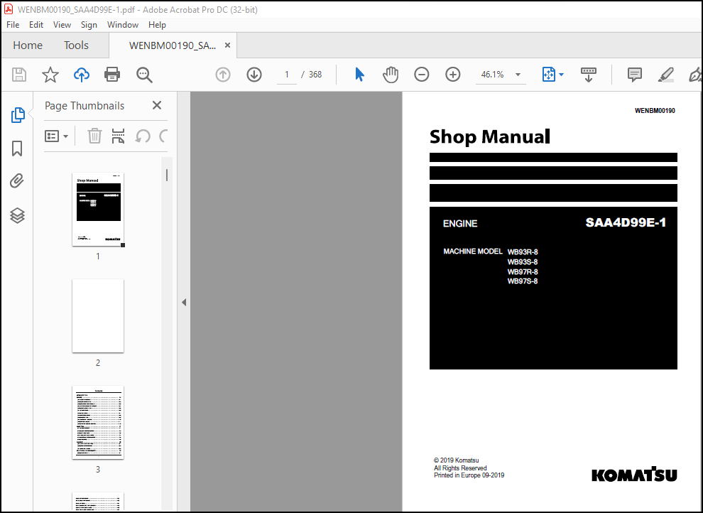
Komatsu WB93R-8 WB93S-8 WB97R-8 WB97S-8 Engine Shop Manual – PDF DOWNLOAD
Komatsu WB93R-8 WB93S-8 WB97R-8 WB97S-8 Engine Shop Manual – PDF DOWNLOAD
FILE DETAILS:
Komatsu WB93R-8 WB93S-8 WB97R-8 WB97S-8 Engine Shop Manual – PDF DOWNLOAD
Language : English
Pages : 368
Downloadable : Yes
File Type : PDF
Size: 30.6 MB
IMAGES PREVIEW OF THE MANUAL:


DESCRIPTION:
Komatsu WB93R-8 WB93S-8 WB97R-8 WB97S-8 Engine Shop Manual – PDF DOWNLOAD
- The Komatsu WB93R-8, WB93S-8, WB97R-8, and WB97S-8 are four models of backhoe loaders with different engine specifications. The engine shop manual for these models covers the Komatsu SAA4D95LE-3 engine, which is a four-stroke, four-cylinder diesel engine with a displacement of 3.26 liters. The manual provides detailed information on the maintenance, repair, and troubleshooting of the engine, including specifications, testing procedures, and adjustments.
- The manual is organized into sections covering different aspects of the engine. The first section provides general information on the engine, including specifications, system configuration, and service standards. The second section covers the structure and function of the engine components, including the engine block, cylinder head, fuel system, lubrication system, cooling system, and electrical system.
- The third section covers the engine testing and adjusting procedures, including inspection and measurement, testing of engine components, and adjustment of engine settings. This section provides detailed step-by-step instructions and illustrations for all testing and adjusting procedures.
- The fourth section covers the engine troubleshooting procedures, including diagnosing and correcting problems with the engine components and systems. This section provides a detailed troubleshooting chart with step-by-step procedures for identifying and correcting engine problems.
- The fifth section covers the engine disassembly and assembly procedures, including removal and installation of major engine components. This section provides detailed step-by-step instructions and illustrations for all disassembly and assembly procedures.
- The sixth section covers the engine maintenance procedures, including routine maintenance tasks such as oil and filter changes, and the replacement of parts such as belts, hoses, and filters.
- Overall, the Komatsu WB93R-8, WB93S-8, WB97R-8, and WB97S-8 Engine Shop Manual is a comprehensive guide to the maintenance, repair, and troubleshooting of the SAA4D95LE-3 engine, providing detailed information on all aspects of the engine’s operation and maintenance.
TABLE OF CONTENTS:
Komatsu WB93R-8 WB93S-8 WB97R-8 WB97S-8 Engine Shop Manual – PDF DOWNLOAD
INTRODUCTION………………………………………………………………………………………………………….. 5
Foreword …………………………………………………………………………………………………………. 7
International symbols ……………………………………………………………………………………………… 9
SYMBOLS – WARNINGS……………………………………………………………………………………………… 9
Grouped Safety Message …………………………………………………………………………………………….. 10
Grouped Safety Message …………………………………………………………………………………………….. 12
Grounding and screening…………………………………………………………………………………………. 12
Optional electrical and mechanical parts installations……………………………………………………………… 14
Safety rules ……………………………………………………………………………………………………… 15
Standard safety precautions……………………………………………………………………………………… 15
Accident prevention…………………………………………………………………………………………….. 15
During maintenance……………………………………………………………………………………………… 15
Protection of the environment……………………………………………………………………………………. 16
Conversion factors ………………………………………………………………………………………………… 17
Conversions between the main units of measurements of the international system and the most commonly used derived units……. 17
Power…………………………………………………………………………………………………………. 17
Torque………………………………………………………………………………………………………… 17
Rpm…………………………………………………………………………………………………………… 17
Pressure………………………………………………………………………………………………………. 17
Temperature……………………………………………………………………………………………………. 17
Product identification Identification plate ………………………………………………………………………….. 18
Product identification – Correspondence between technical codes and commercial codes ……………………………………… 19
Product identification – Technical coding ……………………………………………………………………………. 20
Product identification – Commercial coding …………………………………………………………………………… 21
Scheduled maintenance ……………………………………………………………………………………………… 22
Introduction…………………………………………………………………………………………………… 22
Checks and scheduled maintenance procedures……………………………………………………………………….. 22
Scheduled maintenance ATS system ……………………………………………………………………………………. 24
ATS system maintenance services schedule………………………………………………………………………….. 24
ENGINE……………………………………………………………………………………………………………….. 25
ENGINE ASSEMBLY……………………………………………………………………………………………………. 25
ENGINE………………………………………………………………………………………………………… 25
540110 ENGINE – Engine horse power ……………………………………………………………………….. 30
Characteristic curves 75kw……………………………………………………………………………….. 30
540110 ENGINE – Technical Data …………………………………………………………………………… 30
GENERAL CHARACTERISTICS………………………………………………………………………………….. 30
540110 ENGINE – Technical Data and assembly clearances ……………………………………………………… 33
540110 ENGINE – Torque ………………………………………………………………………………….. 37
ENGINE………………………………………………………………………………………………………… 25
540110 ENGINE – External view ……………………………………………………………………………. 42
ISOMETRIC VIEW………………………………………………………………………………………….. 42
540110 ENGINE – External view F5BFL413G*B001 ………………………………………………………………. 44
LEFT SIDE VIEW………………………………………………………………………………………….. 44
RIGHT SIDE VIEW…………………………………………………………………………………………. 45
FRONT VIEW……………………………………………………………………………………………… 46
REAR VIEW………………………………………………………………………………………………. 47
TOP VIEW……………………………………………………………………………………………….. 48
540110 ENGINE – Component localisation ……………………………………………………………………. 49
Location of engine electrical components…………………………………………………………………… 49
540110 ENGINE – Component localisation – ATS system ………………………………………………………… 51
Location of the ATS system electrical components……………………………………………………………. 51
ENGINE………………………………………………………………………………………………………… 25
540110 ENGINE – Disassemble ……………………………………………………………………………… 53
Assembly on the stand and draining of the engine lubricant…………………………………………………… 53
Engine cable removal…………………………………………………………………………………….. 55
Removal of the glow plug bridle…………………………………………………………………………… 56
Removal of the electric starter motor……………………………………………………………………… 57
Removal of speed and timing sensor………………………………………………………………………… 57
Removal of boost pressure and exhaust gas absolute pressure sensors…………………………………………… 57
Air pressure control valve removal………………………………………………………………………… 58
Removal of the coolant inlet pipe…………………………………………………………………………. 59
Removal of the turbocharger oil pipes……………………………………………………………………… 59
Removal of temperature sensor and thermostat……………………………………………………………….. 60
Removal of the EGR system………………………………………………………………………………… 60
Turbocharger and exhaust manifold removal………………………………………………………………….. 62
Removal of the air accumulator……………………………………………………………………………. 63
Removal of the water pump/alternator drive belt…………………………………………………………….. 63
Alternator removal………………………………………………………………………………………. 64
Removal of the lower alternator mount……………………………………………………………………… 64
Fuel filter removal……………………………………………………………………………………… 64
Removal of the fuel filter support………………………………………………………………………… 64
Fuel pipes removal………………………………………………………………………………………. 65
Removal of the common rail……………………………………………………………………………….. 66
Removal of the injector fuel return pipe…………………………………………………………………… 67
Removing the oil filter and bracket……………………………………………………………………….. 67
Blow-by filter removal…………………………………………………………………………………… 68
Removing the power take-off (PTO)…………………………………………………………………………. 69
Removal of the high pressure fuel pump…………………………………………………………………….. 69
Removal of the crankshaft pulley………………………………………………………………………….. 70
Water pump removal………………………………………………………………………………………. 70
Removal of the fan drive pulley…………………………………………………………………………… 70
Removal of the engine lubricant heat exchanger……………………………………………………………… 71
Crankshaft front gasket removal…………………………………………………………………………… 71
Front cover removal……………………………………………………………………………………… 71
Removal of the engine air intake………………………………………………………………………….. 72
Throttle body removal (TVA)………………………………………………………………………………. 72
Intake manifold removal………………………………………………………………………………….. 72
Removal of glow plugs……………………………………………………………………………………. 73
Removal of electronic injectors…………………………………………………………………………… 73
Removal of head cover……………………………………………………………………………………. 74
Overhead removal………………………………………………………………………………………… 74
Rocker arms assembly removal……………………………………………………………………………… 75
Cylinder head removal……………………………………………………………………………………. 75
Idle gear removal……………………………………………………………………………………….. 76
Removal of the timing gear……………………………………………………………………………….. 76
Removal of the gear case…………………………………………………………………………………. 77
Removing the oil pump……………………………………………………………………………………. 77
Oil sump removal………………………………………………………………………………………… 77
Removal of the oil intake suction strainer…………………………………………………………………. 78
Removal of complete flywheel……………………………………………………………………………… 78
Crankshaft rear gasket removal……………………………………………………………………………. 79
Flywheel housing removal…………………………………………………………………………………. 79
Piston removal………………………………………………………………………………………….. 80
Connecting rod removal…………………………………………………………………………………… 80
Big-end bearings removal…………………………………………………………………………………. 80
Crankshaft removal………………………………………………………………………………………. 81
Main bearings removal……………………………………………………………………………………. 82
Sprayer removal…………………………………………………………………………………………. 82
Camshaft of distribution removal………………………………………………………………………….. 82
Tappet removal………………………………………………………………………………………….. 83
Removal of piston-connecting rod assembly………………………………………………………………….. 83
Piston rings removal…………………………………………………………………………………….. 84
Removal of rail pressure sensor…………………………………………………………………………… 84
Removal of pressure relief valve on rail…………………………………………………………………… 84
Valve removal…………………………………………………………………………………………… 85
540110 ENGINE – Check …………………………………………………………………………………… 86
Cylinder liner measurement……………………………………………………………………………….. 86
Checking cylinder block head contact surface……………………………………………………………….. 88
TIMING GEAR…………………………………………………………………………………………….. 88
Camshaft of distribution measurement………………………………………………………………………. 88
Checking cam lift and journals alignment…………………………………………………………………… 89
Check and measurement of camshaft bushes…………………………………………………………………… 89
Camshaft bushes replacement………………………………………………………………………………. 90
Tappet measurement………………………………………………………………………………………. 91
Crankshaft measurement…………………………………………………………………………………… 91
MAIN CRANKSHAFT TOLERANCES……………………………………………………………………………….. 93
CLASS OF IMPORTANCE……………………………………………………………………………………… 93
Checking crankshaft shoulder clearance…………………………………………………………………….. 95
Piston, pin and circlip main data…………………………………………………………………………. 95
Measuring the piston diameter…………………………………………………………………………….. 96
NO TITLE……………………………………………………………………………………………….. 0
Piston pin measurement…………………………………………………………………………………… 96
Conditions for correct pin/piston coupling…………………………………………………………………. 97
Measuring seal rings…………………………………………………………………………………….. 97
Connecting rod measurement……………………………………………………………………………….. 98
Connecting rod small end bush check……………………………………………………………………….. 99
Connecting rod axes parallelism check………………………………………………………………………100
Torsion check……………………………………………………………………………………………100
Bending check……………………………………………………………………………………………101
Cylinder head hydraulic seal check…………………………………………………………………………101
Cylinder head contact surface check………………………………………………………………………..102
Cleaning and testing valves……………………………………………………………………………….103
Measuring valves…………………………………………………………………………………………103
Checking clearance between valve stem and valve guide and centring valves………………………………………103
Measuring valve guides……………………………………………………………………………………104
Replacing the valve guides………………………………………………………………………………..105
Boring the valve guides…………………………………………………………………………………..106
Regrinding – replacing the valve seats……………………………………………………………………..106
Checking valve recessing………………………………………………………………………………….108
Valve spring check……………………………………………………………………………………….108
Rod check……………………………………………………………………………………………….108
Rocker assembly check…………………………………………………………………………………….109
540110 ENGINE – Assemble …………………………………………………………………………………110
Tappet installation………………………………………………………………………………………112
Fitting camshaft…………………………………………………………………………………………113
Oil sprayer assembly……………………………………………………………………………………..114
Main bearings assembly……………………………………………………………………………………114
Crankshaft assembly………………………………………………………………………………………115
Finding main journals clearance……………………………………………………………………………115
Conditions………………………………………………………………………………………………115
Piston assembly………………………………………………………………………………………….117
Fitting piston rings……………………………………………………………………………………..118
Big-end bearings assembly…………………………………………………………………………………118
Fitting the connecting rod-piston assembly into the cylinder liners……………………………………………118
Crankpin assembly clearance measurement…………………………………………………………………….120
Piston protrusion check…………………………………………………………………………………..121
Rail pressure sensor assembly……………………………………………………………………………..122
Assembly of pressure relief valve on rail…………………………………………………………………..122
Valve fitting……………………………………………………………………………………………122
Flywheel housing assembly…………………………………………………………………………………123
Crankshaft rear gasket assembly……………………………………………………………………………124
Engine flywheel assembly………………………………………………………………………………….124
Oil intake suction strainer assembly……………………………………………………………………….125
Oil sump assembly………………………………………………………………………………………..126
Installing the oil pump…………………………………………………………………………………..126
Gear case assembly……………………………………………………………………………………….127
Assembly of the timing gear……………………………………………………………………………….128
Idle gear assembly……………………………………………………………………………………….129
Assembly of the high pressure fuel pump ……………………………………………………………………129
Assembling the power take-off (PTO)………………………………………………………………………..130
Assembling the front cover………………………………………………………………………………..130
Crankshaft front gasket installation……………………………………………………………………….131
Assembly of the engine lubricant heat exchanger……………………………………………………………..131
Cylinder head installation………………………………………………………………………………..132
Rocker arms assembly installation …………………………………………………………………………134
Overhead assembly………………………………………………………………………………………..135
Installation of head cover………………………………………………………………………………..135
Assembling electro-injectors ……………………………………………………………………………..136
Assembly of the injector fuel return pipe…………………………………………………………………..136
Inlet manifold assembly ………………………………………………………………………………….137
Throttle body assembly (TVA)………………………………………………………………………………137
Assembly of the engine air intake………………………………………………………………………….138
Assembly of the crankshaft pulley………………………………………………………………………….138
Assembly of the fan drive pulley…………………………………………………………………………..138
Water pump assembly ……………………………………………………………………………………..139
Blow-by filter assembly ………………………………………………………………………………….139
Glow plug assembly……………………………………………………………………………………….140
Oil filter and mount assembly……………………………………………………………………………..140
Installation of the common rail……………………………………………………………………………141
Fuel pipe assembly……………………………………………………………………………………….142
Assembly of the fuel filter mount………………………………………………………………………….143
Fuel filter assembly……………………………………………………………………………………..143
Assembly of the air accumulator……………………………………………………………………………144
Assembly of the lower alternator mount …………………………………………………………………….144
Alternator assembly………………………………………………………………………………………144
Assembly of the water pump/alternator drive belt…………………………………………………………….144
Auxiliary members’ belt tension……………………………………………………………………………145
Turbocharger and exhaust manifold assembly………………………………………………………………….146
Assembly of the EGR system………………………………………………………………………………..146
Thermostat and temperature sensor assembly………………………………………………………………….148
Assembly of the turbocharger oil pipes …………………………………………………………………….149
Assembly of the coolant inlet pipe…………………………………………………………………………149
Air pressure control valve assembly………………………………………………………………………..149
Assembly of the exhaust gas and air temperature sensors………………………………………………………150
Assembly of the engine speed and timing sensors……………………………………………………………..151
Mounting the electric starter motor………………………………………………………………………..151
Assembly of the glow plug bridle…………………………………………………………………………..151
Fitting the engine cable………………………………………………………………………………….152
Removal of rotating stand…………………………………………………………………………………154
ENGINE MOUNTING……………………………………………………………………………………………………. 25
OIL SUMP………………………………………………………………………………………………………. 25
540430 OIL SUMP – Overview ……………………………………………………………………………….156
ENGINE BREATHER………………………………………………………………………………………………… 25
540480 ENGINE BREATHER – Overview – Oil vapour recirculation system …………………………………………..157
Blow-by filter…………………………………………………………………………………………..158
OIL SUMP………………………………………………………………………………………………………. 25
540430 OIL SUMP – Remove …………………………………………………………………………………159
540430 OIL SUMP – Install ………………………………………………………………………………..160
CRANKSHAFT FRONT SEAL…………………………………………………………………………………………… 26
540442 CRANKSHAFT FRONT SEAL – Remove ……………………………………………………………………..161
Crankshaft front seal ring removal…………………………………………………………………………161
540442 CRANKSHAFT FRONT SEAL – Install …………………………………………………………………….162
Crankshaft front seal ring refitting……………………………………………………………………….162
CRANKSHAFT REAR SEAL……………………………………………………………………………………………. 26
540462 CRANKSHAFT REAR SEAL – Remove ………………………………………………………………………163
Crankshaft rear seal ring removal………………………………………………………………………….163
540462 CRANKSHAFT REAR SEAL – Install ……………………………………………………………………..164
Crankshaft rear seal ring refitting………………………………………………………………………..164
ENGINE BREATHER………………………………………………………………………………………………… 26
540480 ENGINE BREATHER – Remove …………………………………………………………………………..165
Blow-by filter removal……………………………………………………………………………………165
540480 ENGINE BREATHER – Install ………………………………………………………………………….166
Blow-by filter refitting………………………………………………………………………………….166
FILTER ELEMENT…………………………………………………………………………………………………. 26
540486 FILTER ELEMENT – Replace …………………………………………………………………………..167
Blow-by filter change…………………………………………………………………………………….167
CYLINDER HEAD ASSEMBLY……………………………………………………………………………………………… 26
CYLINDER HEAD………………………………………………………………………………………………….. 26
540610 CYLINDER HEAD – Remove …………………………………………………………………………….168
540610 CYLINDER HEAD – Install ……………………………………………………………………………169
ROCKER COVER…………………………………………………………………………………………………… 26
540630 ROCKER COVER – Remove ……………………………………………………………………………..172
540630 ROCKER COVER – Install …………………………………………………………………………….173
INTAKE+EXHAUST MANIFOLDS……………………………………………………………………………………………. 26
EGR ASSEMBLY…………………………………………………………………………………………………… 26
540740 EGR ASSEMBLY – Overview ……………………………………………………………………………174
Operation diagram………………………………………………………………………………………..175
MODULATING SOLENOID VALVE……………………………………………………………………………………….. 26
540746 MODULATING SOLENOID VALVE – Overview ………………………………………………………………..176
Exhaust gas valve (EGR)…………………………………………………………………………………..176
Sensor-actuator pin-out…………………………………………………………………………………..176
ABSOLUTE PRESSURE SENSOR………………………………………………………………………………………… 26
540751 ABSOLUTE PRESSURE SENSOR – Overview …………………………………………………………………177
Absolute exhaust gas pressure sensor……………………………………………………………………….177
Sensor pin-out…………………………………………………………………………………………..177
THROTTLE VALVE POS SENSOR……………………………………………………………………………………….. 26
540762 THROTTLE VALVE POS SENSOR – Overview ………………………………………………………………..178
Throttle body (TVA)………………………………………………………………………………………178
Sensor-actuator pin-out…………………………………………………………………………………..178
INTAKE MANIFOLDS……………………………………………………………………………………………….. 26
540710 INTAKE MANIFOLDS – Remove ………………………………………………………………………….179
540710 INTAKE MANIFOLDS – Install …………………………………………………………………………180
EXHAUST MANIFOLD……………………………………………………………………………………………….. 26
540720 EXHAUST MANIFOLD – Remove ………………………………………………………………………….181
540720 EXHAUST MANIFOLD – Install …………………………………………………………………………182
EGR ASSEMBLY…………………………………………………………………………………………………… 26
540740 EGR ASSEMBLY – Remove ……………………………………………………………………………..183
540740 EGR ASSEMBLY – Install …………………………………………………………………………….185
ENGINE COMPONENTS………………………………………………………………………………………………….. 27
CRANKSHAFT PULLEY………………………………………………………………………………………………. 27
540821 CRANKSHAFT PULLEY – Remove …………………………………………………………………………187
540821 CRANKSHAFT PULLEY – Install ………………………………………………………………………..188
FLYWHEEL ASSEMBLY………………………………………………………………………………………………. 27
540850 FLYWHEEL ASSEMBLY – Remove …………………………………………………………………………189
540850 FLYWHEEL ASSEMBLY – Install ………………………………………………………………………..190
TIMING GEAR……………………………………………………………………………………………………….. 27
ROCKER ARM ASSY………………………………………………………………………………………………… 27
541230 ROCKER ARM ASSY – Remove …………………………………………………………………………..191
541230 ROCKER ARM ASSY – Install ………………………………………………………………………….192
FUEL SUPPLY……………………………………………………………………………………………………….. 27
FUEL SUPPLY……………………………………………………………………………………………………. 27
5420 FUEL SUPPLY – Overview ………………………………………………………………………………193
SUPPLY SYSTEM……………………………………………………………………………………………193
Fuel system diagram………………………………………………………………………………………193
5420 FUEL SUPPLY – Overview – Electrical system …………………………………………………………….195
Air pressure/temperature sensor……………………………………………………………………………196
Engine oil temperature and pressure sensor………………………………………………………………….196
Fuel pressure sensor……………………………………………………………………………………..196
Fuel temperature sensor…………………………………………………………………………………..196
Coolant temperature sensor………………………………………………………………………………..196
Crankshaft sensor………………………………………………………………………………………..196
Timing sensor……………………………………………………………………………………………196
Self-diagnostics…………………………………………………………………………………………196
Engine pre-heating resistance management……………………………………………………………………196
Synchronisation search……………………………………………………………………………………196
Injection control………………………………………………………………………………………..196
Closed loop injection pressure check……………………………………………………………………….197
Pilot and main injection advance control……………………………………………………………………197
Idle speed control……………………………………………………………………………………….197
Maximum speed limiting……………………………………………………………………………………197
Cut Off…………………………………………………………………………………………………197
Smokiness on acceleration control………………………………………………………………………….197
Checking fuel temperature…………………………………………………………………………………197
After Run……………………………………………………………………………………………….197
5420 FUEL SUPPLY – Overview – Hydraulic system ……………………………………………………………..198
HYDRAULIC SYSTEM…………………………………………………………………………………………198
FILTER ASSEMBLY………………………………………………………………………………………………… 27
542010 FILTER ASSEMBLY – Overview …………………………………………………………………………200
Fuel filter……………………………………………………………………………………………..200
FILTER ASSEMBLY………………………………………………………………………………………………… 27
542010 FILTER ASSEMBLY – Replace ………………………………………………………………………….201
Fuel filter replacement…………………………………………………………………………………..201
542010 FILTER ASSEMBLY – Remove …………………………………………………………………………..203
542010 FILTER ASSEMBLY – Install ………………………………………………………………………….204
FILTER SUPPORT…………………………………………………………………………………………………. 27
542014 FILTER SUPPORT – Remove ……………………………………………………………………………205
Removal of fuel filter support…………………………………………………………………………….205
542014 FILTER SUPPORT – Install …………………………………………………………………………..206
Fuel filter support refitting……………………………………………………………………………..206
PIPES…………………………………………………………………………………………………………. 27
542020 PIPES – Remove ……………………………………………………………………………………207
Removal of fuel pipes…………………………………………………………………………………….207
542020 PIPES – Install …………………………………………………………………………………..209
Refitting fuel pipes……………………………………………………………………………………..209
SUPERCHARGING……………………………………………………………………………………………………… 27
SUPERCHARGING………………………………………………………………………………………………….. 28
5424 SUPERCHARGING – Overview …………………………………………………………………………….211
TURBO CHARGER………………………………………………………………………………………………….. 28
542410 TURBO CHARGER – Overview …………………………………………………………………………..212
Waste Gate Valve…………………………………………………………………………………………213
PRESS.LIMITING SWITCH…………………………………………………………………………………………… 28
542419 PRESS.LIMITING SWITCH – Overview ……………………………………………………………………214
V.G.T.DRIVE ACTUATOR……………………………………………………………………………………………. 28
542451 V.G.T.DRIVE ACTUATOR – Overview …………………………………………………………………….215
TURBO CHARGER………………………………………………………………………………………………….. 28
542410 TURBO CHARGER – Remove …………………………………………………………………………….216
542410 TURBO CHARGER – Install ……………………………………………………………………………217
542410 TURBO CHARGER – Visual inspection …………………………………………………………………..218
Turbocharger visual inspection…………………………………………………………………………….218
LUBRICATION……………………………………………………………………………………………………….. 28
LUBRICATION……………………………………………………………………………………………………. 28
5430 LUBRICATION – Overview ………………………………………………………………………………219
LUBRICATION CIRCUIT………………………………………………………………………………………219
Lubrication system diagram………………………………………………………………………………..219
Lubrication circuit ……………………………………………………………………………………..221
OIL PUMP………………………………………………………………………………………………………. 28
543010 OIL PUMP – Overview ……………………………………………………………………………….222
Oil pump cross-section……………………………………………………………………………………222
FILTER CARTRIDGE……………………………………………………………………………………………….. 28
543070 FILTER CARTRIDGE – Overview ………………………………………………………………………..223
Engine oil filter………………………………………………………………………………………..223
OIL PRESSURE REGUL.VALVE………………………………………………………………………………………… 28
543075 OIL PRESSURE REGUL.VALVE – Overview …………………………………………………………………224
Oil pressure regulating valves (4 – 10bar)………………………………………………………………….224
Oil pressure regulating valve (4bar)……………………………………………………………………….224
Safety valve (10bar)……………………………………………………………………………………..225
FILTER CARTRIDGE……………………………………………………………………………………………….. 28
543070 FILTER CARTRIDGE – Check …………………………………………………………………………..226
Engine lubricant oil level check…………………………………………………………………………..226
543070 FILTER CARTRIDGE – Change fluid …………………………………………………………………….227
Engine lubricant oil replacement…………………………………………………………………………..227
543070 FILTER CARTRIDGE – Replace …………………………………………………………………………228
543070 FILTER CARTRIDGE – Remove ………………………………………………………………………….230
543070 FILTER CARTRIDGE – Install …………………………………………………………………………231
FILTER SUPPORT…………………………………………………………………………………………………. 28
543072 FILTER SUPPORT – Remove – Oil filter bracket …………………………………………………………232
543072 FILTER SUPPORT – Install – Oil filter bracket ………………………………………………………..233
LUBRICANT COOLING………………………………………………………………………………………………….. 28
HEAT EXCHANGER…………………………………………………………………………………………………. 28
543110 HEAT EXCHANGER – Overview ………………………………………………………………………….234
HEAT EXCHANGER…………………………………………………………………………………………………. 29
543110 HEAT EXCHANGER – Remove ……………………………………………………………………………235
543110 HEAT EXCHANGER – Install …………………………………………………………………………..236
WATER COOLING……………………………………………………………………………………………………… 29
WATER COOLING………………………………………………………………………………………………….. 29
5432 WATER COOLING – Overview – Cooling circuit …………………………………………………………….237
Cooling system diagram with ………………………………………………………………………………237
WATER PUMP ASSEMBLY…………………………………………………………………………………………….. 29
543210 WATER PUMP ASSEMBLY – Overview ……………………………………………………………………..239
Section on water pump…………………………………………………………………………………….239
THERMOSTAT…………………………………………………………………………………………………….. 29
543250 THERMOSTAT – Overview ……………………………………………………………………………..240
Thermostat operating diagram………………………………………………………………………………240
Operation……………………………………………………………………………………………….240
functional diagram……………………………………………………………………………………….241
WATER PUMP ASSEMBLY…………………………………………………………………………………………….. 29
543210 WATER PUMP ASSEMBLY – Remove ……………………………………………………………………….242
543210 WATER PUMP ASSEMBLY – Install ………………………………………………………………………243
543210 WATER PUMP ASSEMBLY – Check ………………………………………………………………………..244
Water pump………………………………………………………………………………………………244
THERMOSTAT…………………………………………………………………………………………………….. 29
543250 THERMOSTAT – Remove ……………………………………………………………………………….245
543250 THERMOSTAT – Install ………………………………………………………………………………246
FAN AND COOLING CONTROL…………………………………………………………………………………………….. 29
WATER PUMP DRIVE BELT…………………………………………………………………………………………… 29
543411 WATER PUMP DRIVE BELT – Check ………………………………………………………………………247
Main activity……………………………………………………………………………………………247
Auxiliary members’ belt tension……………………………………………………………………………247
543411 WATER PUMP DRIVE BELT – Replace …………………………………………………………………….249
Auxiliary members’ belt replacement………………………………………………………………………..249
Auxiliary members’ belt tension……………………………………………………………………………249
543411 WATER PUMP DRIVE BELT – Remove ……………………………………………………………………..251
Removal…………………………………………………………………………………………………251
543411 WATER PUMP DRIVE BELT – Install …………………………………………………………………….252
INJECTION……………………………………………………………………………………………………………..257
INJECTION PUMP……………………………………………………………………………………………………..257
INJECTION PUMP ASSY……………………………………………………………………………………………..257
771010 INJECTION PUMP ASSY – Overview – High pressure pump BOSCH CP4.1 ………………………………………..259
High pressure pump CP4.1 operating diagrams…………………………………………………………………261
HIGH PRESSURE ADJ UNIT…………………………………………………………………………………………..257
771034 HIGH PRESSURE ADJ UNIT – Overview …………………………………………………………………..263
High pressure fuel pump dosing unit………………………………………………………………………..263
Valve pin-out……………………………………………………………………………………………264
INJECTION PUMP ASSY……………………………………………………………………………………………..257
771010 INJECTION PUMP ASSY – Remove ……………………………………………………………………….265
High-pressure pump removal………………………………………………………………………………..265
771010 INJECTION PUMP ASSY – Install ………………………………………………………………………268
High-pressure pump refitting………………………………………………………………………………268
ELECTRONIC GOVERNOR…………………………………………………………………………………………………257
AIR PRESSURE SENSOR……………………………………………………………………………………………..257
772646 AIR PRESSURE SENSOR – Overview ……………………………………………………………………..271
Air temperature and boost pressure sensor…………………………………………………………………..271
Sensor pin-out…………………………………………………………………………………………..271
FUEL TEMPERATURE SENSOR………………………………………………………………………………………….257
772656 FUEL TEMPERATURE SENSOR – Overview ………………………………………………………………….272
Fuel temperature sensor…………………………………………………………………………………..272
Sensor pin-out…………………………………………………………………………………………..272
LIFT FEED PUMP……………………………………………………………………………………………………..257
FEED PUMP ASSY………………………………………………………………………………………………….257
773010 FEED PUMP ASSY – Overview Checking the mechanical feed pump (ZP18) ……………………………………..273
AUXILIARY FUEL FILTERS………………………………………………………………………………………………257
FUEL PRE-FILTER…………………………………………………………………………………………………257
773110 FUEL PRE-FILTER – Check ……………………………………………………………………………274
Check for water in fuel pre-filter…………………………………………………………………………274
HYDRAULIC ACCUMULATOR……………………………………………………………………………………………….258
HIGH PRESS ACCUMULATOR…………………………………………………………………………………………..258
774510 HIGH PRESS ACCUMULATOR – Overview …………………………………………………………………..275
PRESSURE SENSOR…………………………………………………………………………………………………258
774511 PRESSURE SENSOR – Overview …………………………………………………………………………276
Fuel pressure sensor on rail………………………………………………………………………………276
HIGH PRESS ACCUMULATOR…………………………………………………………………………………………..258
774510 HIGH PRESS ACCUMULATOR – Remove …………………………………………………………………….277
Common Rail removal………………………………………………………………………………………277
774510 HIGH PRESS ACCUMULATOR – Install ……………………………………………………………………278
INJECTORS………………………………………………………………………………………………………….258
INJECTOR……………………………………………………………………………………………………….258
775010 INJECTOR – Overview ……………………………………………………………………………….279
Electro-injectors………………………………………………………………………………………..279
Start of injection……………………………………………………………………………………….279
End of injection…………………………………………………………………………………………279
Electro-injector pin – out………………………………………………………………………………..279
INJECTOR……………………………………………………………………………………………………….258
775010 INJECTOR – Remove …………………………………………………………………………………281
775010 INJECTOR – Install ………………………………………………………………………………..282
CHASSIS……………………………………………………………………………………………………………….285
AIR FILTERS AND PIPES……………………………………………………………………………………………….285
AIR FILTERS AND PIPES……………………………………………………………………………………………285
5051 AIR FILTERS AND PIPES – Check ………………………………………………………………………..287
Check of the air filter…………………………………………………………………………………..287
RADIATOR AND PIPES………………………………………………………………………………………………….285
RADIATOR……………………………………………………………………………………………………….285
506010 RADIATOR – Check ………………………………………………………………………………….288
Checking the engine coolant level………………………………………………………………………….288
506010 RADIATOR – Cleaning ……………………………………………………………………………….289
506010 RADIATOR – Cleaning – Clean/replace radiator pressure cap ……………………………………………..290
506010 RADIATOR – Change fluid ……………………………………………………………………………291
Replacing engine coolant………………………………………………………………………………….291
AD-BLUE SYSTEM……………………………………………………………………………………………………..285
AD-BLUE UNIT PUMP MODULE…………………………………………………………………………………………285
507410 AD-BLUE UNIT PUMP MODULE – Technical Data ……………………………………………………………292
AdBlue module connector…………………………………………………………………………………..292
AdBlue supply module pin-out………………………………………………………………………………292
AD-BLUE SYSTEM………………………………………………………………………………………………….285
5074 AD-BLUE SYSTEM – Overview ……………………………………………………………………………293
ATS system heating/cooling system………………………………………………………………………….296
AdBlue specifications…………………………………………………………………………………….298
5074 AD-BLUE SYSTEM – Component localisation ……………………………………………………………….299
Location of the ATS system filters…………………………………………………………………………299
AD-BLUE UNIT PUMP MODULE…………………………………………………………………………………………285
507410 AD-BLUE UNIT PUMP MODULE – Overview DeNOx 2.2 (SM) ……………………………………………………300
Supply module……………………………………………………………………………………………300
AD-BLUE TANK……………………………………………………………………………………………………285
507420 AD-BLUE TANK – Overview ……………………………………………………………………………302
AD-BLUE INDICATOR……………………………………………………………………………………………….285
507424 AD-BLUE INDICATOR – Overview ……………………………………………………………………….303
AdBlue level multifunction unit (MFU)………………………………………………………………………303
Functional wiring diagram…………………………………………………………………………………304
AD-BLUE METERING DEV MODU………………………………………………………………………………………..285
507431 AD-BLUE METERING DEV MODU – Overview Dosing module 2.5 ………………………………………………..305
CROSSOVER VALVE…………………………………………………………………………………………………285
507433 CROSSOVER VALVE – Overview …………………………………………………………………………306
Engine coolant 3-way valve (component not supplied by FPT)……………………………………………………306
TEMPERATURE SENSOR………………………………………………………………………………………………286
507434 TEMPERATURE SENSOR – Overview – Exhaust gas temperature sensor …………………………………………307
Sensor pin-out…………………………………………………………………………………………..308
507434 TEMPERATURE SENSOR – Overview – Air temperature sensor ………………………………………………..309
Sensor pin-out…………………………………………………………………………………………..309
NOX DETECTION SENSOR…………………………………………………………………………………………….286
507435 NOX DETECTION SENSOR – Overview …………………………………………………………………….310
Nitrogen oxide detecting sensor …………………………………………………………………………..310
NOx control unit…………………………………………………………………………………………311
Upstream NOx sensor pin-out……………………………………………………………………………….312
Pin-Out NOx sensor downstream……………………………………………………………………………..312
NOx Sensor………………………………………………………………………………………………312
Technical specifications………………………………………………………………………………….312
NH3 DETECTION SENSOR…………………………………………………………………………………………….286
507437 NH3 DETECTION SENSOR – Overview …………………………………………………………………….314
Ammonia detection sensor NH3………………………………………………………………………………314
Technical specifications………………………………………………………………………………….314
NH3 SENSOR CONTROL UNIT………………………………………………………………………………………….286
507439 NH3 SENSOR CONTROL UNIT – Overview ………………………………………………………………….316
Ammonia detection control unit (NH3)……………………………………………………………………….316
NH3 control unit…………………………………………………………………………………………316
Recommended assembly position……………………………………………………………………………..317
Technical specifications………………………………………………………………………………….317
Pin – out……………………………………………………………………………………………….317
PIPES AND SLEEVES……………………………………………………………………………………………….286
507467 PIPES AND SLEEVES – Overview – Exhaust gas mixer pipe between the turbocharger and DOC catalytic converter ….319
AD-BLUE FILTER………………………………………………………………………………………………….286
507413 AD-BLUE FILTER – Replace …………………………………………………………………………..320
Removal…………………………………………………………………………………………………320
Assembly………………………………………………………………………………………………..322
ELECTRICAL COMPONENTS…………………………………………………………………………………………………..325
ALTERNATOR…………………………………………………………………………………………………………325
ALTERNATOR ASSEMBLY……………………………………………………………………………………………..325
760310 ALTERNATOR ASSEMBLY – Overview ……………………………………………………………………..327
Alternator………………………………………………………………………………………………327
Technical view…………………………………………………………………………………………..327
Characteristic curves…………………………………………………………………………………….327
Characteristics………………………………………………………………………………………….328
ALTERNATOR ASSEMBLY……………………………………………………………………………………………..325
760310 ALTERNATOR ASSEMBLY – Remove ……………………………………………………………………….329
760310 ALTERNATOR ASSEMBLY – Install ………………………………………………………………………330
760310 ALTERNATOR ASSEMBLY – Visual inspection ……………………………………………………………..331
STARTER MOTOR………………………………………………………………………………………………………325
STARTER MOTOR ASSY………………………………………………………………………………………………325
760810 STARTER MOTOR ASSY – Overview ………………………………………………………………………332
Technical view…………………………………………………………………………………………..332
Electric diagram…………………………………………………………………………………………332
Characteristics………………………………………………………………………………………….332
Tightening torques……………………………………………………………………………………….333
STARTER MOTOR ASSY………………………………………………………………………………………………325
760810 STARTER MOTOR ASSY – Remove ………………………………………………………………………..334
760810 STARTER MOTOR ASSY – Install ……………………………………………………………………….335
760810 STARTER MOTOR ASSY – Check …………………………………………………………………………336
Starter motor inspection………………………………………………………………………………….336
COLD START DEVICE…………………………………………………………………………………………………..325
PREHEATER PLUGS…………………………………………………………………………………………………325
761915 PREHEATER PLUGS – Overview …………………………………………………………………………337
Pre-heating glow plugs……………………………………………………………………………………337
Glow plug section pin – out……………………………………………………………………………….337
Glow plug control unit……………………………………………………………………………………338
Technical specifications………………………………………………………………………………….338
Glow plug control unit Pin – Out…………………………………………………………………………..338
PREHEATER PLUGS…………………………………………………………………………………………………325
761915 PREHEATER PLUGS – Remove – Glow plugs bridle …………………………………………………………339
761915 PREHEATER PLUGS – Install – Glow plugs bridle ………………………………………………………..340
BATTERIES………………………………………………………………………………………………………….326
BATTERY………………………………………………………………………………………………………..326
762010 BATTERY – Check – Battery check …………………………………………………………………….341
GAUGES,INDICATORS,SENDERS……………………………………………………………………………………………326
OIL PRESSURE SENDER……………………………………………………………………………………………..326
764251 OIL PRESSURE SENDER – Overview ……………………………………………………………………..342
Low engine oil pressure sensor…………………………………………………………………………….342
Sensor pin-out…………………………………………………………………………………………..342
WATER TEMPERATURE SENDER…………………………………………………………………………………………326
764254 WATER TEMPERATURE SENDER – Overview …………………………………………………………………344
Coolant temperature sensor………………………………………………………………………………..344
Sensor pin-out…………………………………………………………………………………………..344
REV.COUNTER SENDER………………………………………………………………………………………………326
764263 REV.COUNTER SENDER – Overview ………………………………………………………………………345
Crankshaft speed sensor (incremental speed)…………………………………………………………………345
Sensor pin-out…………………………………………………………………………………………..345
CAMSHAFT SPEED SENDER……………………………………………………………………………………………326
764264 CAMSHAFT SPEED SENDER – Overview ……………………………………………………………………346
Camshaft timing sensor (segmental speed)……………………………………………………………………346
Sensor pin-out…………………………………………………………………………………………..346
CTR UNIT,RESIST,FUSES……………………………………………………………………………………………….326
ENGINE DRIVE CONTR.UNIT………………………………………………………………………………………….326
766161 ENGINE DRIVE CONTR.UNIT – Overview ………………………………………………………………….347
electronic control unitEDC 17C49 ………………………………………………………………………….347
Location of the EDC 17C49 control unit connectors …………………………………………………………..348
System functionsEDC 17C49 ………………………………………………………………………………..348
Fuel metering……………………………………………………………………………………………349
Correcting flow rate according to water temperature………………………………………………………….349
De-rating……………………………………………………………………………………………….349
Closed loop injection pressure check……………………………………………………………………….349
Injection advance electronic check…………………………………………………………………………350
Engine speed limiter……………………………………………………………………………………..350
Starting the engine ……………………………………………………………………………………..350
Cold starting……………………………………………………………………………………………350
Warm starting……………………………………………………………………………………………350
Run Up………………………………………………………………………………………………….350
After run……………………………………………………………………………………………….351
Cut-off…………………………………………………………………………………………………351
Cylinder Balancing……………………………………………………………………………………….351
Synchronisation Search……………………………………………………………………………………351
766161 ENGINE DRIVE CONTR.UNIT – Overview – Pin out …………………………………………………………352
Colour key………………………………………………………………………………………………352
Pin Out connector 60 Pin………………………………………………………………………………….352
766161 ENGINE DRIVE CONTR.UNIT – Electrical schema ………………………………………………………….354
EDC 17C49 electric control unit diagram (60 pin connector)……………………………………………………354
KEY…………………………………………………………………………………………………….354
Glow plug pre-heating system electrical connection…………………………………………………………..356
DeNOx 6.5 power supply module electrical connection………………………………………………………….357
NH₃ – NOx system ATS (SCR) sensors electrical connection……………………………………………………..358
ATS (SCR) system temperature sensors electrical connection……………………………………………………359
Pin Out 94 Pin connector for parts not provided by FPT……………………………………………………….360
CABLES AND CONNECTIONS………………………………………………………………………………………………326
ENGINE CABLES…………………………………………………………………………………………………..326
769140 ENGINE CABLES – Overview …………………………………………………………………………..361
Cable on engine………………………………………………………………………………………….361
ENGINE CABLES…………………………………………………………………………………………………..326
769140 ENGINE CABLES – Remove …………………………………………………………………………….363
769140 ENGINE CABLES – Install ……………………………………………………………………………364
More products