$41
Komatsu WD600-6R Wheel Dozer Shop Manual SEN06588-06 – PDF DOWNLOAD
Komatsu WD600-6R Wheel Dozer Shop Manual SEN06588-06 – PDF DOWNLOAD
FILE DETAILS:
Komatsu WD600-6R Wheel Dozer Shop Manual SEN06588-06 – PDF DOWNLOAD
Language : English
Pages : 1840
Downloadable : Yes
File Type : PDF
Size: 135.6 MB
IMAGES PREVIEW OF THE MANUAL:
DESCRIPTION:
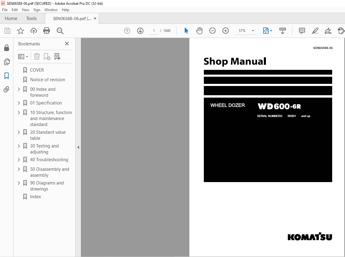
Komatsu WD600-6R Wheel Dozer Shop Manual SEN06588-06 – PDF DOWNLOAD
SERIAL NUMBERS 60001 and up
Foreword and general information :
Safety notice :
Important safety notice:
Proper service and repair are extremely important for safe machine operation. The service and repair
techniques recommended by Komatsu and described in this manual are both effective and safe.
Some of these techniques require the use of tools specially designed by Komatsu for the specific
purpose.
To prevent injury to workers, the symbol k is used to mark safety precautions in this manual. The
cautions accompanying these symbols should always be followed carefully. If any dangerous situation
arises or may possibly arise, first consider safety, and take the necessary actions to deal with
the situation.
1. General precautions :
1) Before carrying out any greasing or repairs, read all the safety labels stuck to the machine. For the locations of the safety labels and detailed explanation of precautions, see the Operation and Maintenance Manual.2) Decide a place in the repair workshop to keep tools and removed parts. Always keep the tools and parts in their correct places. Always keep the work area clean and make sure that there is no dirt, water, or oil on the floor. Smoke only in the areas provided for smoking. Never smoke while working.
3) When carrying out any operation, always wear safety shoes and helmet. Do not wear loose work clothes, or clothes with buttons missing.
- Always wear safety glasses when hitting parts with a hammer.
- Always wear safety glasses when grinding parts with a grinder, etc.
4) When carrying out any operation with 2 or more workers, always agree on the operating procedure before starting. Always inform your fellow workers before starting any step of the operation. Before starting work, hang UNDER REPAIR warning signs in the operator’s compartment.5) Only qualified workers must carry out work and operation which require license or qualification. 6) Keep all tools in good condition, learn the correct way to use them, and use the proper ones of them. Before starting work, thoroughly check the tools, machine, forklift, service car, etc.
TABLE OF CONTENTS:
Komatsu WD600-6R Wheel Dozer Shop Manual SEN06588-06 – PDF DOWNLOAD
00 Index and foreword
Table of contents ………………………………………………………………………………………………………………………..00-2
Foreword and general information……………………………………………………………………………………………..00-14
Safety notice………………………………………………………………………………………………………………………….00-14
How to read the shop manual …………………………………………………………………………………………………00-19
Explanation of terms for maintenance standard ……………………………………………………………………….00-21
Handling of electric equipment and hydraulic component …………………………………………………………00-23
Handling of connectors newly used for engines ……………………………………………………………………….00-32
How to read electric wire code………………………………………………………………………………………………..00-35
Precautions when carrying out operation…………………………………………………………………………………00-38
Method of disassembling and connecting push-pull type coupler………………………………………………00-41
Standard tightening torque table……………………………………………………………………………………………..00-44
Conversion table ……………………………………………………………………………………………………………………00-48
01 Specification
Specification and technical data…………………………………………………………………………………………………..01-3
Specification dimension drawing……………………………………………………………………………………………….01-3
Specifications ………………………………………………………………………………………………………………………….01-4
Weight table…………………………………………………………………………………………………………………………….01-7
Table of fuel, coolant and lubricants ………………………………………………………………………………………….01-9
10 Structure, function and maintenance standard
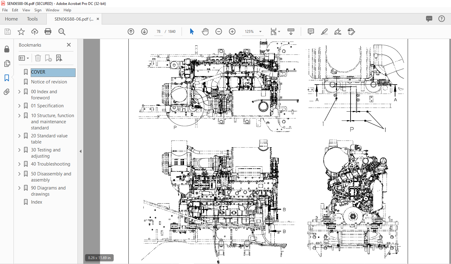
Engine and cooling system………………………………………………………………………………………………………….10-4
Engine mount and transmission mount……………………………………………………………………………………..10-4
Damper …………………………………………………………………………………………………………………………………..10-6
Cooling system………………………………………………………………………………………………………………………..10-8
Cooling fan pump………………………………………………………………………………………………………………….. 10-12
Cooling fan motor………………………………………………………………………………………………………………….. 10-20
Power train……………………………………………………………………………………………………………………………….10-26
Power train ……………………………………………………………………………………………………………………………10-26
Power train system diagram……………………………………………………………………………………………………10-27
Torque converter and transmission piping diagram…………………………………………………………………..10-28
Torque converter ……………………………………………………………………………………………………………………10-30
Modulation clutch ………………………………………………………………………………………………………………….. 10-39
Torque converter regulator valve …………………………………………………………………………………………….10-40
Transmission …………………………………………………………………………………………………………………………10-42
Transfer…………………………………………………………………………………………………………………………………10-62
Transmission control valve……………………………………………………………………………………………………..10-64
ECMV……………………………………………………………………………………………………………………………………10-66
Main relief valve and torque converter relief valve ……………………………………………………………………10-73
Lubrication relief valve……………………………………………………………………………………………………………10-75
Torque converter oil cooler ……………………………………………………………………………………………………..10-76
Torque converter oil filter ………………………………………………………………………………………………………..10-77
Drive shaft……………………………………………………………………………………………………………………………..10-79
Center support……………………………………………………………………………………………………………………….10-82
Axle ………………………………………………………………………………………………………………………………………10-84
Differential……………………………………………………………………………………………………………………………..10-88
Limited slip differential ……………………………………………………………………………………………………………10-97
Final drive ……………………………………………………………………………………………………………………………10-102
Steering system………………………………………………………………………………………………………………………10-106
Steering piping diagram………………………………………………………………………………………………………..10-106
Steering column ………………………………………………………………………………………………………………….. 10-108
Joystick steering lever linkage ………………………………………………………………………………………………10-109
Joystick EPC valve ……………………………………………………………………………………………………………… 10-110
Lock valve…………………………………………………………………………………………………………………………….10-111
Steering valve……………………………………………………………………………………………………………………… 10-112
WD600-6R 00-3
(05)
00 Index and foreword
Rotary valve …………………………………………………………………………………………………………………………10-115
Steering control valve……………………………………………………………………………………………………………10-118
Two-way restrictor valve ……………………………………………………………………………………………………….10-134
Stop valve ……………………………………………………………………………………………………………………………10-135
Steering pump………………………………………………………………………………………………………………………10-136
Steering cylinder …………………………………………………………………………………………………………………..10-150
Emergency steering piping diagram ………………………………………………………………………………………10-151
Diverter valve……………………………………………………………………………………………………………………….10-152
Emergency steering pump…………………………………………………………………………………………………….10-160
Brake system ………………………………………………………………………………………………………………………….10-162
Brake piping diagram……………………………………………………………………………………………………………10-162
Brake …………………………………………………………………………………………………………………………………..10-164
Brake valve ………………………………………………………………………………………………………………………….10-168
Accumulator charge valve …………………………………………………………………………………………………….10-176
EPC relief valve ……………………………………………………………………………………………………………………10-182
Accumulator (for brake) ………………………………………………………………………………………………………..10-184
Slack adjuster ………………………………………………………………………………………………………………………10-186
Parking brake……………………………………………………………………………………………………………………….10-190
Parking brake solenoid valve…………………………………………………………………………………………………10-192
Emergency parking brake release valve…………………………………………………………………………………10-194
Brake cooling pump ……………………………………………………………………………………………………………..10-195
Undercarriage and frame …………………………………………………………………………………………………………10-196
Axle mount …………………………………………………………………………………………………………………………..10-196
Center hinge pin …………………………………………………………………………………………………………………..10-201
Hydraulic system …………………………………………………………………………………………………………………….10-204
Hydraulic piping diagram ………………………………………………………………………………………………………10-204
Work equipment control lever linkage…………………………………………………………………………………….10-206
Hydraulic tank ………………………………………………………………………………………………………………………10-208
Work equipment pump………………………………………………………………………………………………………….10-210
Control valve………………………………………………………………………………………………………………………..10-230
CLSS…………………………………………………………………………………………………………………………………..10-244
Functions and operation by valve ………………………………………………………………………………………….10-248
Accumulator (for PPC circuit) ………………………………………………………………………………………………..10-258
Triple pump ………………………………………………………………………………………………………………………….10-259
Work equipment………………………………………………………………………………………………………………………10-260
Work equipment linkage ……………………………………………………………………………………………………….10-260
Cutting edge and end bit……………………………………………………………………………………………………….10-263
Work equipment lubrication …………………………………………………………………………………………………..10-265
Hydraulic cylinder …………………………………………………………………………………………………………………10-268
Cab and its attachments…………………………………………………………………………………………………………..10-270
ROPS cab ……………………………………………………………………………………………………………………………10-270
Air conditioner………………………………………………………………………………………………………………………10-272
Electrical system……………………………………………………………………………………………………………………..10-276
Machine monitor system……………………………………………………………………………………………………….10-276
Machine monitor …………………………………………………………………………………………………………………..10-282
Work equipment control system…………………………………………………………………………………………….10-330
Transmission controller system……………………………………………………………………………………………..10-356
Electric transmission control………………………………………………………………………………………………….10-388
Engine starting/stopping circuit ……………………………………………………………………………………………..10-390
Parking brake circuit……………………………………………………………………………………………………………..10-393
Sensor …………………………………………………………………………………………………………………………………10-397
VHMS controller related………………………………………………………………………………………………………..10-418
VHMS controller and wireless LAN system …………………………………………………………………….10-419-1
Electric lever (Work equipment) …………………………………………………………………………………………….10-423
20 Standard value table
Standard service value table………………………………………………………………………………………………………..20-3
Standard service value table for engine……………………………………………………………………………………..20-3
00-4 WD600-6R
(05)
00 Index and foreword
Standard service value table for chassis…………………………………………………………………………………… 20-4
30 Testing and adjusting
Related information on testing and adjusting……………………………………………………………………………….. 30-4
Tools for testing, adjusting, and troubleshooting ……………………………………………………………………….. 30-4
Engine and cooling system…………………………………………………………………………………………………………. 30-9
Measuring engine speed …………………………………………………………………………………………………………. 30-9
Measuring exhaust gas color …………………………………………………………………………………………………. 30-11
Measuring exhaust temperature …………………………………………………………………………………………….. 30-12
Adjusting valve clearance………………………………………………………………………………………………………. 30-14
Testing compression pressures ……………………………………………………………………………………………… 30-16
Measuring blowby pressure …………………………………………………………………………………………………… 30-19
Measuring engine oil pressure……………………………………………………………………………………………….. 30-20
Measuring intake air (boost) pressure…………………………………………………………………………………….. 30-21
Handling fuel system equipment…………………………………………………………………………………………….. 30-22
Releasing residual pressure in fuel system …………………………………………………………………………….. 30-22
Testing fuel pressures……………………………………………………………………………………………………………. 30-23
Testing return rate and leakage ……………………………………………………………………………………………… 30-24
Bleeding air from fuel circuit…………………………………………………………………………………………………… 30-27
Testing leakage in fuel system……………………………………………………………………………………………….. 30-29
Handling reduced cylinder mode operation …………………………………………………………………………….. 30-30
Handling no-injection cranking operation ………………………………………………………………………………… 30-30
Handling controller voltage circuit…………………………………………………………………………………………… 30-31
Replacing and adjusting alternator and air conditioner compressor belt tension………………………… 30-32
Power train………………………………………………………………………………………………………………………………. 30-33
Adjusting modulation clutch speed sensor and speed sensor…………………………………………………… 30-33
Measuring directional lever and gear shift lever (Steering wheel specification)………………………….. 30-35
Testing and adjusting power train oil pressure…………………………………………………………………………. 30-36
Flushing procedure for torque converter and transmission hydraulic circuit ………………………………. 30-50
Method of moving machine when transmission valve is broken ……………………………………………….. 30-52
Moving method of machine disabled by short-to-power failure in work equipment potentiometer .. 30-54
Steering system……………………………………………………………………………………………………………………….. 30-56
Adjusting steering stop valve …………………………………………………………………………………………………. 30-56
Measuring operating effort of AJSS lever (AJSS specification) ………………………………………………… 30-57
Testing and adjusting AJSS lever angle sensor and frame angle sensor (AJSS specification)……. 30-58
Testing and adjusting steering stopper bolt (AJSS specification)………………………………………………. 30-60
Testing and adjusting steering wheel (Steering wheel specification) …………………………………………. 30-62
Testing steering oil pressure ………………………………………………………………………………………………….. 30-64
Bleeding air from steering cylinder circuit ……………………………………………………………………………….. 30-68
Testing hydraulic drive fan……………………………………………………………………………………………………… 30-69
Bleeding air from hydraulic drive fan circuit …………………………………………………………………………….. 30-72
Brake system…………………………………………………………………………………………………………………………… 30-74
Measuring brake pedal ………………………………………………………………………………………………………….. 30-74
Measuring brake performance ……………………………………………………………………………………………….. 30-75
Testing and adjusting accumulator charge pressure………………………………………………………………… 30-76
Testing of accumulator nitrogen gas pressure and procedure for charging brake
accumulator with nitrogen gas ……………………………………………………………………………………………..30-77-1
Testing wheel brake oil pressure ……………………………………………………………………………………………. 30-78
Measuring wear of wheel brake disc ………………………………………………………………………………………. 30-80
Bleeding air from wheel brake circuit………………………………………………………………………………………. 30-81
Releasing residual pressure in brake accumulator circuit ………………………………………………………… 30-82
Testing parking brake performance ………………………………………………………………………………………… 30-83
Measuring parking brake oil pressure …………………………………………………………………………………….. 30-84
Testing wear of parking brake disc …………………………………………………………………………………………. 30-87
Method of releasing parking brake manually …………………………………………………………………………… 30-88
Hydraulic system ……………………………………………………………………………………………………………………… 30-89
Measuring and adjusting work equipment control lever……………………………………………………………. 30-89
Measuring work equipment oil pressure …………………………………………………………………………………. 30-90
WD600-6R 00-5
(05)
00 Index and foreword
Releasing residual pressure in work equipment circuit………………………………………………………. 30-94-1
Bleeding air from work equipment circuit………………………………………………………………………………….30-95
Cab and its attachments…………………………………………………………………………………………………………….30-96
Moving machine for removing operator cab……………………………………………………………………………..30-96
Electrical system……………………………………………………………………………………………………………………….30-98
Preparations for work on troubleshooting of electric system………………………………………………………30-98
Procedure for testing diodes………………………………………………………………………………………………….30-102
Machine monitor-based adjustment at replacement, disassembly and assembly, and additional
installation for each sensor and controller……………………………………………………………………………….. 30-103
Special functions of machine monitor (EMMS) ……………………………………………………………………….30-107
VHMS controller initial setting procedure (ORBCOMM installation specification) …………………….30-176
VHMS controller initial setting procedure (IRIDIUM installation specification)……………………….30-197-1
Precautions for replacing VHMS controller…………………………………………………………………………30-198
Initialization of VHMS wireless LAN modem and downloading of data………………………………..30-203-1
Pm-clinic…………………………………………………………………………………………………………………………………30-204
Pm-clinic inspection table ……………………………………………………………………………………………………..30-204
40 Troubleshooting
Related information on troubleshooting ………………………………………………………………………………………..40-9
Points to remember when performing troubleshooting………………………………………………………………..40-9
How to proceed in troubleshooting ………………………………………………………………………………………….40-11
Testing before troubleshooting ………………………………………………………………………………………………..40-13
Classification and procedures of troubleshooting ……………………………………………………………………..40-14
Failure codes list…………………………………………………………………………………………………………………….40-18
Information in troubleshooting table…………………………………………………………………………………………40-30
Troubleshooting method for disconnecting wiring harness of pressure sensor system………………..40-32
Connection table for connector pin numbers…………………………………………………………………………….40-35
T- branch box and T- branch adapter table ………………………………………………………………………………40-71
Fuse locations………………………………………………………………………………………………………………………..40-74
Troubleshooting by failure code (Display of code) ……………………………………………………………………….40-77
Failure code [1500L0] TORQFLOW transmission: Double meshing…………………………………………..40-77
Failure code [15B0NX] Transmission Oil Filter Clogging …………………………………………………………..40-78
Failure code [15SAL1] ECMV F clutch: When command current is OFF, fill signal is ON…………….40-80
Failure code [15SALH] ECMV F clutch: When command current is ON, fill signal is OFF …………..40-82
Failure code [15SBL1] ECMV R clutch: When command current is OFF, fill signal is ON……………40-84
Failure code [15SBLH] ECMV R clutch: When command current is ON, fill signal is OFF …………..40-86
Failure code [15SEL1] ECMV (1): When command current is OFF, fill signal is ON……………………40-88
Failure code [15SELH] ECMV (1): When command current is ON, fill signal is OFF …………………..40-90
Failure code [15SFL1] ECMV (2): When command current is OFF, fill signal is ON ……………………40-92
Failure code [15SFLH] ECMV (2): When command current is ON, fill signal is OFF …………………..40-94
Failure code [15SGL1] ECMV (3): When command current is OFF, fill signal is ON……………………40-96
Failure code [15SGLH] ECMV (3): When command current is ON, fill signal is OFF…………………..40-98
Failure code [15SHL1] ECMV (4): When command current is OFF, fill signal is ON………………….40-100
Failure code [15SHLH] ECMV (4): When command current is ON, fill signal is OFF…………………40-102
Failure code [15W0NT] Transmission modulation clutch: Overheating …………………………………….40-104
Failure code [2F00MA] Parking brake: Malfunction…………………………………………………………………40-105
Failure code [2G42ZG] Front Accumulator Oil Pressure Low…………………………………………………..40-108
Failure code [2G43ZG] Rear Accumulator Oil Pressure Low…………………………………………………..40-110
Failure code [A000N1] (or VHMS_LED display: “n2” → “01”) Engine: Overrun…………………………40-113
Failure code [AA1ANX] Air Cleaner Clogging …………………………………………………………………………40-114
Failure code [AB00L6] Alternator: Signal disagrees with run and stop of engine ………………………40-116
Failure code [AB00MA] Alternator: Malfunction ………………………………………………………………………40-118
Failure code [B@BAZG] Engine oil pressure: Low error………………………………………………………….40-120
Failure code [B@BAZK] Eng Oil Level Low……………………………………………………………………………40-121
Failure code [B@BCNS] Engine coolant temperature: Overheating…………………………………………40-122
Failure code [B@BCZK] Engine coolant level low…………………………………………………………………..40-124
Failure code [B@C7NS] Brake oil overheating……………………………………………………………………….40-126
Failure code [b@CENS] Torque converter oil overheating ………………………………………………………40-127
00-6 WD600-6R
(05)
00 Index and foreword
Failure code [B@CENS] Torque converter oil overheating……………………………………………………… 40-128
Failure code [B@GAZK] Low Battery Fluid Level ………………………………………………………………….. 40-129
Failure code [B@HANS] Hyd Oil Overheat……………………………………………………………………………. 40-130
Failure code [CA111] Abnormality in engine controller …………………………………………………………… 40-132
Failure code [CA115] Engine Ne or Bkup speed sensor error…………………………………………………. 40-135
Failure code [CA122] Charge (boost) pressure sensor high error …………………………………………… 40-136
Failure code [CA123] Charge (boost) pressure sensor low error…………………………………………….. 40-138
Failure code [CA131] Throttle sensor high error ……………………………………………………………………. 40-140
Failure code [CA132] Throttle sensor low error……………………………………………………………………… 40-143
Failure code [CA135] Engine oil pressure sensor high error…………………………………………………… 40-146
Failure code [CA141] Engine oil pressure sensor low error ……………………………………………………. 40-148
Failure code [CA144] Coolant temperature sensor high error…………………………………………………. 40-150
Failure code [CA145] Coolant temperature sensor low error ………………………………………………….. 40-152
Failure code [CA153] Charge (boost) temperature sensor high error………………………………………. 40-154
Failure code [CA154] Charge (boost) temperature sensor low error ……………………………………….. 40-156
Failure code [CA187] Sensor power supply 2 low error………………………………………………………….. 40-158
Failure code [CA212] Engine oil temperature sensor high error ……………………………………………… 40-160
Failure code [CA213] Engine oil temperature sensor low error……………………………………………….. 40-162
Failure code [CA221] Atmospheric pressure sensor high error ………………………………………………. 40-164
Failure code [CA222] Atmospheric pressure sensor low error………………………………………………… 40-166
Failure code [CA227] Sensor power supply 2 high error ………………………………………………………… 40-168
Failure code [CA234] Engine overspeed ………………………………………………………………………………. 40-169
Failure code [CA238] Ne speed sensor power supply error……………………………………………………. 40-170
Failure code [CA263] Fuel temperature sensor high error ……………………………………………………… 40-172
Failure code [CA265] Fuel temperature sensor low error……………………………………………………….. 40-174
Failure code [CA271] PCV1 Short circuit ………………………………………………………………………………. 40-176
Failure code [CA272] PCV1 Disconnection …………………………………………………………………………… 40-177
Failure code [CA273] PCV2 Short circuit ………………………………………………………………………………. 40-178
Failure code [CA274] PCV2 Disconnection …………………………………………………………………………… 40-179
Failure code [CA322] Injector #1 open/short error …………………………………………………………………. 40-180
Failure code [CA323] Injector #5 open/short error …………………………………………………………………. 40-182
Failure code [CA324] Injector #3 open/short error …………………………………………………………………. 40-184
Failure code [CA325] Injector #6 open/short error …………………………………………………………………. 40-186
Failure code [CA331] Injector #2 open/short error …………………………………………………………………. 40-188
Failure code [CA332] Injector #4 open/short error …………………………………………………………………. 40-190
Failure code [CA342] Calibration code inconsistency…………………………………………………………….. 40-192
Failure code [CA351] Injectors drive circuit error …………………………………………………………………… 40-193
Failure code [CA352] Sensor power supply 1 low error………………………………………………………….. 40-194
Failure code [CA386] Sensor power supply 1 high error ………………………………………………………… 40-196
Failure code [CA431] Idle validation switch error …………………………………………………………………… 40-197
Failure code [CA432] Idle validation action error……………………………………………………………………. 40-200
Failure code [CA441] Battery voltage low error ……………………………………………………………………… 40-203
Failure code [CA442] Battery voltage high error ……………………………………………………………………. 40-204
Failure code [CA449] Common rail pressure high error 2 ………………………………………………………. 40-205
Failure code [CA451] Common rail pressure sensor high error ………………………………………………. 40-206
Failure code [CA452] Common rail pressure sensor low error ……………………………………………….. 40-208
Failure code [CA553] Common rail pressure high error 1 ………………………………………………………. 40-210
Failure code [CA554] Common rail pressure sensor in range error ………………………………………… 40-211
Failure code [CA559] Supply pump pressure very low error 1………………………………………………… 40-212
Failure code [CA689] Engine Ne speed sensor error …………………………………………………………….. 40-216
Failure code [CA731] Engine Bkup speed sensor phase error ……………………………………………….. 40-218
Failure code [CA757] All continuous data lost error ……………………………………………………………….. 40-219
Failure code [CA778] Engine Bkup speed sensor error………………………………………………………….. 40-220
Failure code [CA1633] KOMNET datalink timeout error …………………………………………………………. 40-222
Failure code [CA2185] Throttle sensor supply voltage high error ……………………………………………. 40-224
Failure code [CA2186] Throttle sensor power supply low error ………………………………………………. 40-226
Failure code [CA2249] Supply pump pressure very low error 2………………………………………………. 40-228
Failure code [CA2555] Intake air heater relay open circuit error……………………………………………… 40-230
WD600-6R 00-7
(05)
00 Index and foreword
Failure code [CA2556] Intake air heater relay short circuit error ………………………………………………40-232
Failure code [D191KA] AJSS neutral safety relay open circuit…………………………………………………40-234
Failure code [D191KB] AJSS neutral safety relay short circuit…………………………………………………40-236
Failure code [D198KA] Transmission oil pressure bypass solenoid: Disconnection…………………..40-238
Failure code [D198KB] Transmission oil pressure bypass solenoid: Short circuit………………………40-239
Failure code [D198KY] Transmission oil pressure bypass solenoid: Short circuit with power supply line
……………………………………………………………………………………………………………………………………………40-240
Failure code [D5ZHKA] Terminal C signal open circuit…………………………………………………………….40-242
Failure code [D5ZHKB] Terminal C signal short circuit…………………………………………………………….40-244
Failure code [D5ZHKZ] Terminal C signal open or short circuit………………………………………………..40-246
Failure code [D5ZHL6] Terminal C signal disagrees with run and stop of engine………………………40-248
Failure code [DA80L4] Auto-greasing controller disagrees with ON/OFF signal ……………………….40-250
Failure code [DAF3KK] Machine monitor: Source voltage low (input) ………………………………………40-252
Failure code [DAF5KP] Machine monitor: Output voltage low………………………………………………….40-254
Failure code [DAFRKR] CAN communication with machine monitor: Communication error (Abnormality
in target component system) …………………………………………………………………………………………………40-256
Failure code [DAQ0KK] Transmission controller: Source voltage low ………………………………………40-257
Failure code [DAQ0KT] Transmission controller: Defect in controller ……………………………………….40-260
Failure code [DAQ2KK] Transmission controller load power supply line: Source voltage low (Input)
……………………………………………………………………………………………………………………………………………40-262
Failure code [DAQ9KQ] Transmission controller model selection: Model selection signal disagreement
……………………………………………………………………………………………………………………………………………40-265
Failure code [DAQRKR] CAN communication with transmission controller: Communication error
(Abnormality in target component system)……………………………………………………………………………..40-266
Failure code [DAQRMA] Transmission controller (Option setting): Malfunction…………………………40-271
Failure code [DB2RKR] CAN communication from engine controller: Communication error (Abnormality
in target component system) …………………………………………………………………………………………….40-272
Failure code [DB90KK] Work equipment controller: Source voltage low (input) ………………………..40-275
Failure code [DB90KT] Work equipment controller: Defect in controller……………………………………40-278
Failure code [DB92KK] Work equipment controller load power supply line: Source voltage low (input)
……………………………………………………………………………………………………………………………………………40-279
Failure code [DB95KX] Work equipment controller power supply output: Out of range ……………..40-282
Failure code [DB99KQ] Work equipment controller model selection: Model selection signal disagreement……………………………………………………………………………………………………
……………………………….40-284
Failure code [DB9RKR] CAN communication with work equipment controller: Communication error
(Abnormality in target component system)……………………………………………………………………………..40-285
Failure code [DB9RMA] Work equipment controller (Option setting): Malfunction……………………..40-286
Failure code [DB9RMC] CAN communication with transmission controller: Malfunction ……………40-287
Failure code [DBB0KK] or change of VHMS_LED display from “n9” to “01” (VHMS controller: Source
voltage low (input)) ……………………………………………………………………………………………………………….40-288
Failure code [DBB0KQ] or change of VHMS_LED display from “nF” to “11” (VHMS controller: Disagreement
of model selection signals) …………………………………………………………………………………..40-290
Failure code [DBB3KK] or change of VHMS_LED display from “n9” to “05” (VHMS controller battery
power supply: Source voltage low (input))………………………………………………………………………………40-292
Failure code [DBB5KP] or change of VHMS_LED display from “n9” to “04” (VHMS controller 5 V power
supply output: Output voltage low)…………………………………………………………………………………………40-294
Failure code [DBB6KP] or change of VHMS_LED display from “n9” to “02” (VHMS controller 24V
power supply output: Output voltage low) ………………………………………………………………………………40-296
Failure code [DBB7KP] or change of VHMS_LED display from “n9” to “03” (VHMS controller 12V
power supply output: Output voltage low) ………………………………………………………………………………40-298
Failure code [DBBQKR] or change of VHMS_LED display from “n8” to “02” (CAN communication of
VHMS controller: Communication error (Abnormality in target component system))………………….40-300
Failure code [DD15LD] t switch (Panel switch 1): Switch is kept pressed for long time ……………40-302
Failure code [DD16LD] U switch (Panel switch 2): Switch is kept pressed for long time …………..40-304
Failure code [DD17LD] < switch (Panel switch 3): Switch is kept pressed for long time …………….40-306
Failure code [DD18LD] > switch (Panel switch 4): Switch is kept pressed for long time …………….40-308
Failure code [DDA7L4] RPM set ON/OFF switch: ON-OFF signals disagree ……………………………40-310
Failure code [DDA8KB] RPM set idle-up/down selector switch (idle-up): Short circuit……………….40-312
00-8 WD600-6R
(05)
00 Index and foreword
Failure code [DDA9KB] RPM set idle-up/down selector switch (idle-down): Short circuit………….. 40-315
Failure code [DDB6L4] Parking brake switch (Neutralizer): ON/OFF signals disagree……………… 40-318
Failure code [DDD1LD] Pitch operation switch: Switch is kept pressed for long time……………….. 40-322
Failure code [DDDBKA] Traction adjustment dial: Disconnection……………………………………………. 40-324
Failure code [DDDBKB] Traction adjustment dial: Short circuit……………………………………………….. 40-326
Failure code [DDE5MA] Emergency steering drive switch: Malfunction…………………………………… 40-328
Failure code [DDK4KA] AJSS FNR switch: Disconnection……………………………………………………… 40-330
Failure code [DDK4KB] AJSS FNR switch: Short circuit ………………………………………………………… 40-332
Failure code [DDK5L4] AJSS shift-up/down switch: ON/OFF signals disagree………………………… 40-334
Failure code [DDK6KA] FNR lever switch: Disconnection………………………………………………………. 40-337
Failure code [DDK6KB] FNR lever switch: Short circuit………………………………………………………….. 40-340
Failure code [DDP5KA] Lock detection pressure switch of steering lock lever: Disconnection….. 40-342
Failure code [DDT0L4] Shift mode selector switch: ON/OFF signals disagree…………………………. 40-344
Failure code [DDW9LD] Kick-down switch: Switch is kept pressed for long time……………………… 40-346
Failure code [DDWLLD] Hold switch: Switch is kept pressed for long time ……………………………… 40-348
Failure code [DF10KA] Transmission shift lever switch: Disconnection …………………………………… 40-350
Failure code [DF10KB] Transmission shift lever switch: Short circuit ………………………………………. 40-354
Failure code [DGE5KX] (or VHMS_LED display: “n4” → “01”) Atmospheric temperature sensor: Out of
input signal range………………………………………………………………………………………………………………… 40-356
Failure code [DGF1KA] Transmission oil temperature sensor: Disconnection …………………………. 40-358
Failure code [DGF1KB] Transmission oil temperature sensor: Short circuit …………………………….. 40-360
Failure code [DGH2KX] Hydraulic oil temperature sensor: Out of input signal range ……………….. 40-362
Failure code [DGR2KA] Rear brake oil temperature sensor: Disconnection…………………………….. 40-364
Failure code [DGR2KX] Rear brake oil temperature sensor: Out of input signal range …………….. 40-366
Failure code [DGT1KA] Torque converter oil temperature sensor: Disconnection ……………………. 40-368
Failure code [DGT1KB] Torque converter oil temperature sensor: Short circuit ……………………….. 40-370
Failure code [DGT1KX] Torque converter oil temperature sensor: Out of input signal range)……. 40-372
Failure code [DGT4KA] (or VHMS_LED display: “n3” → “12”) Exhaust gas temperature sensor (F):
Disconnection……………………………………………………………………………………………………………………… 40-374
Failure code [DGT4KB] (or VHMS_LED display: “n3” → “11”) Exhaust gas temperature sensor (F):
Short circuit…………………………………………………………………………………………………………………………. 40-377
Failure code [DGT5KA] (or VHMS_LED display: “n3” → “22”) Exhaust gas temperature sensor (R):
Disconnection……………………………………………………………………………………………………………………… 40-380
Failure code [DGT5KB] (or VHMS_LED display: “n3” → “21”) Exhaust gas temperature sensor (R):
Short circuit…………………………………………………………………………………………………………………………. 40-383
Failure code [DH21KA] Work equipment pump oil pressure sensor: Disconnection…………………. 40-386
Failure code [DH21KB] Work equipment pump oil pressure sensor: Short circuit…………………….. 40-388
Failure code [DHE5KB] (or VHMS_LED display: “n3” → “32”) Blow-by pressure sensor: Short circuit
…………………………………………………………………………………………………………………………………………… 40-390
Failure code [DHE5KY] (or VHMS_LED display: “n3” → “31”) Blow-by pressure sensor: Short circuit
with power supply line………………………………………………………………………………………………………….. 40-392
Failure code [DHT2L6] Transmission filter clogging sensor: Signal disagrees with operating state of
engine ………………………………………………………………………………………………………………………………… 40-394
Failure code [DHT8KX] (or VHMS_LED display: “n5” → “33”) Steering oil pressure sensor: Out of input
signal range………………………………………………………………………………………………………………………… 40-396
Failure code [DHTBKA] Modulation clutch oil pressure sensor: Disconnection………………………… 40-400
Failure code [DHTBKB] Modulation clutch oil pressure sensor: Short circuit……………………………. 40-402
Failure code [DHU2KX] (or VHMS_LED display: “n7” → “11”) Front brake oil pressure sensor (F): Out
of input signal range ……………………………………………………………………………………………………………. 40-404
Failure code [DHU3KX] (or VHMS_LED display: “n7” → “12”) Rear brake oil pressure sensor (R): Out
of input signal range ……………………………………………………………………………………………………………. 40-406
Failure code [DK30KA] AJSS lever angle sensor: Disconnection……………………………………………. 40-408
Failure code [DK30KY] AJSS lever angle sensor: Short circuit with power supply line …………….. 40-410
Failure code [DK59KA] Lift EPC lever potentiometer (Main): Disconnection ……………………………. 40-412
Failure code [DK59KY] Lift EPC lever potentiometer (Main): Short circuit with power supply line 40-416
Failure code [DK59L8] Lift EPC lever potentiometer (Main): Analog signals disagree ……………… 40-418
Failure code [DK5AKA] Lift EPC lever potentiometer (Sub): Disconnection …………………………….. 40-421
Failure code [DK5AKY] Lift EPC lever potentiometer (Sub): Short circuit with power supply line. 40-424
WD600-6R 00-9
(05)
00 Index and foreword
Failure code [DK5BKA] Tilt & pitch EPC lever potentiometer (Main): Disconnection …………………40-426
Failure code [DK5BKY] Tilt & pitch EPC lever potentiometer (Main): Short circuit with power supply line
……………………………………………………………………………………………………………………………………………40-430
Failure code [DK5BL8] Tilt & pitch EPC lever potentiometer (Main): Analog signals disagree……40-432
Failure code [DK5CKA] Tilt & pitch EPC lever potentiometer (Sub): Disconnection…………………..40-435
Failure code [DK5CKY] Tilt & pitch EPC lever potentiometer (Sub): Short circuit with power supply line
……………………………………………………………………………………………………………………………………………40-438
Failure code [DKD0KA] Frame angle sensor: Disconnection …………………………………………………..40-440
Failure code [DKD0KY] Frame angle sensor: Short circuit with power supply line…………………….40-442
Failure code [DKD0KZ] AJSS lever and frame angle sensor: Disconnection or short circuit………40-444
Failure code [DLFAKA] Modulation clutch output shaft speed sensor: Disconnection ……………….40-448
Failure code [DLFALC] Modulation clutch output shaft speed sensor: Speed signals disagree ….40-450
Failure code [DLT3KA] Transmission output shaft speed sensor (2): Disconnection …………………40-452
Failure code [DLT3LC] Transmission output shaft speed sensor (2): Speed signals disagree ……40-454
Failure code [DLT4KB] Transmission output shaft speed sensor (1): Short circuit …………………….40-456
Failure code [DLT4KX] Transmission output shaft speed sensor (1): Out of input signal range….40-458
Failure code [DV00KB] Alarm buzzer: Short circuit …………………………………………………………………40-460
Failure code [DW4PKA] Blade raise EPC solenoid: Disconnection ………………………………………….40-462
Failure code [DW4PKB] Blade raise EPC solenoid: Short circuit……………………………………………..40-464
Failure code [DW4PKY] Blade raise EPC solenoid: Short circuit with power supply line……………40-465
Failure code [DW4QKA] Blade lower EPC solenoid: Disconnection…………………………………………40-466
Failure code [DW4QKB] Blade lower EPC solenoid: Short circuit…………………………………………….40-467
Failure code [DW4QKY] Blade lower EPC solenoid: Short circuit with power supply line…………..40-468
Failure code [DW4RKA] Tilt & pitch EPC solenoid: Disconnection …………………………………………..40-469
Failure code [DW4RKB] Tilt & pitch EPC solenoid: Short circuit ………………………………………………40-470
Failure code [DW4RKY] Tilt & pitch EPC solenoid: Short circuit with power supply line …………….40-471
Failure code [DW4SKA] Tilt & pitch EPC solenoid: Disconnection …………………………………………..40-472
Failure code [DW4SKB] Tilt & pitch EPC solenoid: Short circuit ………………………………………………40-473
Failure code [DW4SKY] Tilt & pitch EPC solenoid: Short circuit with power supply line …………….40-474
Failure code [DW7BKA] Fan reverse solenoid: Disconnection…………………………………………………40-476
Failure code [DW7BKB] Fan reverse solenoid: Short circuit ……………………………………………………40-478
Failure code [DW7BKY] Fan reverse solenoid: Short circuit with power supply line ………………….40-480
Failure code [DWM1KA] Work equipment neutral lock solenoid: Disconnection ……………………….40-482
Failure code [DWM1KB] Work equipment neutral lock solenoid: Short circuit …………………………..40-484
Failure code [DWM1KY] Work equipment neutral lock solenoid: Short circuit with power supply line
……………………………………………………………………………………………………………………………………………40-486
Failure code [DWN7KA] Blade float magnet detent solenoid: Disconnection ……………………………40-488
Failure code [DWN7KB] Blade float magnet detent solenoid: Short circuit ……………………………….40-490
Failure code [DWN7KY] Blade float magnet detent solenoid: Short circuit with power supply line
……………………………………………………………………………………………………………………………………………40-492
Failure code [DWNFKA] Modulation clutch cut-off release solenoid: Disconnection………………….40-494
Failure code [DWNFKB] Modulation clutch cut-off release solenoid: Short circuit……………………..40-496
Failure code [DWNFKY] Modulation clutch cut-off release solenoid: Short circuit with power source line
……………………………………………………………………………………………………………………………………………40-498
Failure code [DX16KA] Fan pump EPC solenoid: Disconnection …………………………………………….40-500
Failure code [DX16KB] Fan pump EPC solenoid: Short circuit ………………………………………………..40-501
Failure code [DX16KY] Fan pump EPC solenoid: Short circuit with power supply line ………………40-502
Failure code [DXA1KA] Pump PC-EPC solenoid: Disconnection……………………………………………..40-503
Failure code [DXA1KB] Pump PC-EPC solenoid: Short circuit ………………………………………………..40-504
Failure code [DXF0KA] AJSS EPC solenoid: Disconnection……………………………………………………40-505
Failure code [DXF0KB] AJSS EPC solenoid: Short circuit……………………………………………………….40-506
Failure code [DXH1KA] Lockup ECMV solenoid: Disconnection………………………………………………40-508
Failure code [DXH1KB] Lockup ECMV solenoid: Short circuit …………………………………………………40-510
Failure code [DXH1KY] Lockup ECMV solenoid: Short circuit with power supply line ……………….40-512
Failure code [DXH4KA] 1st clutch ECMV solenoid: Disconnection…………………………………………..40-514
Failure code [DXH4KB] 1st clutch ECMV solenoid: Short circuit………………………………………………40-516
Failure code [DXH4KY] 1st clutch ECMV solenoid: Short circuit with power supply line ……………40-518
Failure code [DXH5KA] 2nd clutch ECMV solenoid: Disconnection …………………………………………40-520
00-10 WD600-6R
(05)
00 Index and foreword
Failure code [DXH5KB] 2nd clutch ECMV solenoid: Short circuit……………………………………………. 40-522
Failure code [DXH5KY] 2nd clutch ECMV solenoid: Short circuit with power supply line………….. 40-524
Failure code [DXH6KA] 3rd clutch ECMV solenoid: Disconnection…………………………………………. 40-526
Failure code [DXH6KB] 3rd clutch ECMV solenoid: Short circuit…………………………………………….. 40-528
Failure code [DXH6KY] 3rd clutch ECMV solenoid: Short circuit with power supply line…………… 40-530
Failure code [DXH7KA] R clutch ECMV solenoid: Disconnection……………………………………………. 40-532
Failure code [DXH7KB] R clutch ECMV solenoid: Short circuit ………………………………………………. 40-534
Failure code [DXH7KY] R clutch ECMV solenoid: Short circuit with power supply line …………….. 40-536
Failure code [DXH8KA] F clutch ECMV solenoid: Disconnection ……………………………………………. 40-538
Failure code [DXH8KB] F clutch ECMV solenoid: Short circuit……………………………………………….. 40-540
Failure code [DXH8KY] F clutch ECMV solenoid: Short circuit with power supply line……………… 40-542
Failure code [DXHHKA] 4th clutch ECMV solenoid: Disconnection ………………………………………… 40-544
Failure code [DXHHKB] 4th clutch ECMV solenoid: Short circuit ……………………………………………. 40-546
Failure code [DXHHKY] 4th clutch ECMV solenoid: Short circuit with power supply line ………….. 40-548
Failure code [DXHJKA] RH pitch REAR EPC solenoid: Disconnection……………………………………. 40-550
Failure code [DXHJKB] RH pitch REAR EPC solenoid: Short circuit ………………………………………. 40-551
Failure code [DXHJKY] RH pitch REAR EPC solenoid: Short circuit with power supply line …….. 40-552
Failure code [DXHKKA] RH pitch FORWARD EPC solenoid: Disconnection …………………………… 40-553
Failure code [DXHKKB] RH pitch FORWARD EPC solenoid: Short circuit ………………………………. 40-554
Failure code [DXHKKY] RH pitch FORWARD EPC solenoid: Short circuit with power supply line
…………………………………………………………………………………………………………………………………………… 40-555
Failure code [DXHPKA] Modulation clutch solenoid: Disconnection ……………………………………….. 40-556
Failure code [DXHPKB] Modulation clutch solenoid: Short circuit …………………………………………… 40-558
Failure code [DXHPKY] Modulation clutch solenoid: Short circuit with power source line…………. 40-560
Failure code [DXHPMA] Modulation clutch solenoid: Malfunction …………………………………………… 40-562
Failure code [F@BBZL] (or VHMS_LED display: “n3” → “38”) Blow-by pressure: High error ……. 40-564
Failure code [F@BYNR] (or VHMS_LED display: “n3” → “62”) Exhaust gas temperature (F): Abnormal
heat ……………………………………………………………………………………………………………………………………. 40-566
Failure code [F@BYNS] (or VHMS_LED display: “n3” → “61”) Exhaust gas temperature (F): Overheat
…………………………………………………………………………………………………………………………………………… 40-568
Failure code [F@BZNR] (or VHMS_LED display: “n3” → “72”) Exhaust gas temperature (R): abnormal
heat ……………………………………………………………………………………………………………………………………. 40-570
Failure code [F@BZNS] (or VHMS_LED display “n3” → “71”) Exhaust gas temperature (R): Overheat
…………………………………………………………………………………………………………………………………………… 40-572
Troubleshooting of electrical system (E-mode)…………………………………………………………………………. 40-574
E-1 Engine does not start…………………………………………………………………………………………………….. 40-574
E-2 Wiper does not operate …………………………………………………………………………………………………. 40-584
E-3 Windshield washer does not operate ……………………………………………………………………………… 40-592
E-4 Headlamp, clearance lamp, tail lamp, and license lamp do not light up or go off ……………….. 40-598
E-5 Working lamp does not light up or go off…………………………………………………………………………. 40-614
E-6 Step lamp does not light up or go off ………………………………………………………………………………. 40-622
E-7 Turn signal lamp and hazard lamp do not light up or go off………………………………………………. 40-624
E-8 Brake lamp does not light or it keeps lighting up. …………………………………………………………….. 40-634
E-9 Backup lamp does not light or it keeps lighting up. ………………………………………………………….. 40-638
E-10 Backup buzzer does not sound or it keeps sounding……………………………………………………… 40-642
E-11 Horn does not sound or it keeps sounding…………………………………………………………………….. 40-646
E-12 Alarm buzzer does not sound or it keeps sounding ……………………………………………………….. 40-650
E-13 Air conditioner does not operate or stop ……………………………………………………………………….. 40-652
E-14 Electric priming pump does not operate or does not stop automatically ………………………….. 40-654
E-15 When starting switch is turned to ON position, machine monitor displays nothing……………. 40-656
Troubleshooting of hydraulic and mechanical system (H-mode)………………………………………………… 40-660
Method of using troubleshooting chart ………………………………………………………………………………….. 40-660
Table of failure modes and causes ……………………………………………………………………………………….. 40-662
H-1 Machine does not start ………………………………………………………………………………………………….. 40-666
H-2 Torque converter lockup is not switched (engine stalls)……………………………………………………. 40-668
H-3 Torque converter lockup is not turned on………………………………………………………………………… 40-669
H-4 Travel speed is slow, thrusting force is weak, uphill traveling power is weak, and gear is not shifted
…………………………………………………………………………………………………………………………………………… 40-670
WD600-6R 00-11
(05)
00 Index and foreword
H-5 Shocks are large at the times of starting and shifting gear ………………………………………………..40-672
H-6 Time lag is large at the times of starting and shifting gear …………………………………………………40-674
H-7 Torque converter oil temperature is high ………………………………………………………………………….40-676
H-8 Steering does not turn [machine with steering wheel] ……………………………………………………….40-677
H-9 Steering does not turn [machine with AJSS]…………………………………………………………………….40-678
H-10 Turning, response of steering is poor [machine with steering wheel] ……………………………….40-679
H-11 Turning, response of AJSS is poor [machine with AJSS]…………………………………………………40-680
H-12 Steering is heavy [machine with steering wheel] …………………………………………………………….40-681
H-13 When machine turns, it shakes or makes large shocks [machine with steering wheel] ……..40-682
H-14 When machine turns, it shakes or makes large shocks [machine with AJSS] …………………..40-683
H-15 Wheel brake does not work or does not work well ………………………………………………………….40-684
H-16 Wheel brake is not released or it drags………………………………………………………………………….40-685
H-17 Parking brake does not work or does not work well ………………………………………………………..40-686
H-18 Parking brake is not released or it drags (including emergency release system) ………………40-687
H-19 Blade does not rise ………………………………………………………………………………………………………40-688
H-20 Blade speed is low or rising force of lift is insufficient ……………………………………………………..40-689
H-21 When rising, blade comes to move slowly at specific height ……………………………………………40-690
H-22 Lift cylinder cannot hold down blade (Blade floats) …………………………………………………………40-690
H-23 Hydraulic drifts of blade occur often……………………………………………………………………………….40-690
H-24 Blade wobbles during operation…………………………………………………………………………………….40-690
H-25 Blade does not tilt and pitch ………………………………………………………………………………………….40-691
H-26 Blade speed is low or tilt and pitch force is insufficient ……………………………………………………40-692
H-27 Blade comes to operate slowly in the midst of tilt and pitch …………………………………………….40-693
H-28 Tilt & pitch cylinder cannot hold down blade…………………………………………………………………..40-693
H-29 Hydraulic drifts of blade occur often……………………………………………………………………………….40-693
H-30 Blade wobbles during travel when loaded (Work equipment valve is set to “HOLD”) ………..40-693
H-31 During operation of machine, engine speed lowers remarkably or engine stalls ……………….40-694
H-32 Large shocks are made when work equipment starts and stops………………………………………40-694
H-33 When work equipment circuit is relieved singly, other work equipment moves………………….40-694
H-34 Fan speed is abnormal (Fan sound and vibration are abnormally large or engine overheats)
……………………………………………………………………………………………………………………………………………40-695
Troubleshooting of engine (S-mode)…………………………………………………………………………………………40-697
Method of using troubleshooting chart……………………………………………………………………………………40-697
S-1 Engine does not start easily…………………………………………………………………………………………….40-700
S-2 Engine does not start ……………………………………………………………………………………………………..40-701
S-3 Engine does not pick up smoothly …………………………………………………………………………………..40-704
S-4 Engine stops during operation…………………………………………………………………………………………40-705
S-5 Engine does not rotate smoothly (Hunting occurs)……………………………………………………………40-706
S-6 Engine lacks output (or lacks power) ……………………………………………………………………………….40-707
S-7 Exhaust smoke is black (Incomplete combustion)…………………………………………………………….40-708
S-8 Oil is consumed much (or exhaust gas color is blue) ………………………………………………………..40-709
S-9 Engine oil becomes contaminated quickly………………………………………………………………………..40-710
S-10 Fuel consumption is excessive………………………………………………………………………………………40-711
S-11 Coolant contains oil (blows back or reduces) ………………………………………………………………….40-712
S-12 Oil pressure drops ………………………………………………………………………………………………………..40-713
S-13 Oil level rises (Water, fuel in oil) …………………………………………………………………………………….40-714
S-14 Coolant temperature rises too high (Overheating)…………………………………………………………..40-715
S-15 Abnormal noise is made ……………………………………………………………………………………………….40-716
S-16 Vibration is excessive……………………………………………………………………………………………………40-717
S-17 Air cannot be bled from fuel circuit…………………………………………………………………………………40-718
50 Disassembly and assembly
General information on disassembly and assembly ………………………………………………………………………50-4
How to read this manual …………………………………………………………………………………………………………..50-4
Coating materials list………………………………………………………………………………………………………………..50-6
Special tools list ……………………………………………………………………………………………………………………….50-9
Sketches of special tools ………………………………………………………………………………………………………..50-13
00-12 WD600-6R
(05)
00 Index and foreword
Engine and cooling system……………………………………………………………………………………………………….. 50-21
Removal and installation of engine assembly………………………………………………………………………….. 50-21
Removal and installation of radiator assembly ………………………………………………………………………… 50-24
Removal and installation of air aftercooler ………………………………………………………………………………. 50-29
Removal and installation of cooling fan and fan motor assembly ……………………………………………… 50-30
Removal and installation of damper assembly ………………………………………………………………………… 50-32
Disassembly and assembly of damper assembly…………………………………………………………………….. 50-34
Removal and installation of fuel tank assembly……………………………………………………………………….. 50-38
Removal and installation of engine hood assembly …………………………………………………………………. 50-40
Removal and installation of bulkhead assembly………………………………………………………………………. 50-42
Removal and installation of fuel supply pump assembly ………………………………………………………….. 50-46
Removal and installation of cylinder head assembly………………………………………………………………… 50-52
Removal and installation of fuel injector assembly…………………………………………………………………… 50-67
Removal and installation of engine front seal ………………………………………………………………………….. 50-71
Removal and installation of engine rear seal …………………………………………………………………………… 50-74
Power train………………………………………………………………………………………………………………………………. 50-78
Removal and installation of parking brake assembly ……………………………………………………………….. 50-78
Removal and installation of torque converter and transmission assembly…………………………………. 50-80
Disassembly and assembly of torque converter assembly……………………………………………………….. 50-85
Disassembly and assembly of transmission assembly …………………………………………………………… 50-112
Disassembly and assembly of transfer assembly…………………………………………………………………… 50-139
Disassembly and assembly of parking brake assembly …………………………………………………………. 50-154
Removal and installation of front axle assembly ……………………………………………………………………. 50-161
Removal and installation of rear axle assembly …………………………………………………………………….. 50-163
Removal and installation of center support assembly…………………………………………………………….. 50-165
Disassembly and assembly of center support assembly ………………………………………………………… 50-167
Disassembly and assembly of differential assembly………………………………………………………………. 50-171
Removal and installation of final drive carrier assembly …………………………………………………………. 50-185
Disassembly and assembly of final drive carrier assembly …………………………………………………….. 50-187
Removal and installation of front final drive brake assembly…………………………………………………… 50-188
Disassembly and assembly of final drive assembly ……………………………………………………………….. 50-190
Brake system…………………………………………………………………………………………………………………………. 50-193
Disassembly and assembly of brake assembly……………………………………………………………………… 50-193
Removal and installation of brake valve assembly…………………………………………………………………. 50-201
Disassembly and assembly of accumulator and charge valve assembly…………………………………. 50-202
Disassembly and assembly of slack adjustor assembly …………………………………………………………. 50-205
Undercarriage and frame………………………………………………………………………………………………………… 50-207
Removal and installation of center hinge pin …………………………………………………………………………. 50-207
Removal and installation of counterweight assembly …………………………………………………………….. 50-214
Hydraulic system ……………………………………………………………………………………………………………………. 50-215
Removal and installation of hydraulic tank assembly……………………………………………………………… 50-215
Removal and installation of hydraulic pump assembly …………………………………………………………… 50-217
Removal and installation of control valve assembly……………………………………………………………….. 50-221
Disassembly and assembly of control valve assembly …………………………………………………………… 50-223
Removal and installation of steering valve assembly……………………………………………………………… 50-228
Disassembly and assembly of hydraulic cylinder assembly ……………………………………………………. 50-229
Work equipment …………………………………………………………………………………………………………………….. 50-234
Removal and installation of work equipment assembly ………………………………………………………….. 50-234
Cab and its attachments …………………………………………………………………………………………………………. 50-238
Removal and installation of operator’s cab assembly …………………………………………………………….. 50-238
Removal and installation of operator’s cab glass (stuck glass) ……………………………………………….. 50-242
Removal and installation of floor frame assembly………………………………………………………………….. 50-250
Disassembly and assembly of operator’s seat assembly ……………………………………………………….. 50-253
Removal and installation of air conditioner unit assembly ………………………………………………………. 50-286
Removal and installation of AJSS lever switch assembly……………………………………………………..50-288-1
Electrical system ……………………………………………………………………………………………………………………. 50-289
Removal and installation of engine controller assembly …………………………………………………………. 50-289
Removal and installation of transmission controller assembly ………………………………………………… 50-291
WD600-6R 00-13
(05)
00 Index and foreword
Removal and installation of loader controller assembly …………………………………………………………..50-291
Removal and installation of VHMS controller assembly…………………………………………………………..50-292
Removal and installation of machine monitor assembly ………………………………………………………….50-293
90 Diagrams and drawings
Hydraulic diagrams and drawings ………………………………………………………………………………………………..90-3
Symbols used in hydraulic circuit diagrams ……………………………………………………………………………….90-3
Power train hydraulic circuit diagram…………………………………………………………………………………………90-5
Brake hydraulic circuit diagram…………………………………………………………………………………………………90-6
Work equipment hydraulic circuit diagram…………………………………………………………………………………90-9
Electrical diagrams and drawings……………………………………………………………………………………………….90-11
Symbols used in electric circuit diagrams…………………………………………………………………………………90-11
Air conditioner electrical circuit diagram…………………………………………………………………………………. 90-15
Electrical circuit diagram …………………………………………………………………………………………………………… 90-17
KOMTRAX electrical circuit diagram (GPRS type) ………………………………………………………………….. 90-37
Connector list and layout ………………………………………………………………………………………………………. 90-39
Index ……………………………………………………………………………………………………………………………………… 1
More products