$45
Kramer Allrad Telehandler 2506 Service Manual PDF DOWNLOAD
Kramer Allrad Telehandler 2506 Service Manual
FILE DETAILS:
Kramer Allrad Telehandler 2506 Service Manual
Language : English
Pages : 420
Downloadable : YES
Format : PDF
Size : 18.0 MB
TABLE OF CONTENTS:
Kramer Allrad Telehandler 2506 Service Manual
1 Cab overview, use, operation
1 1 Machine outside view 1-2
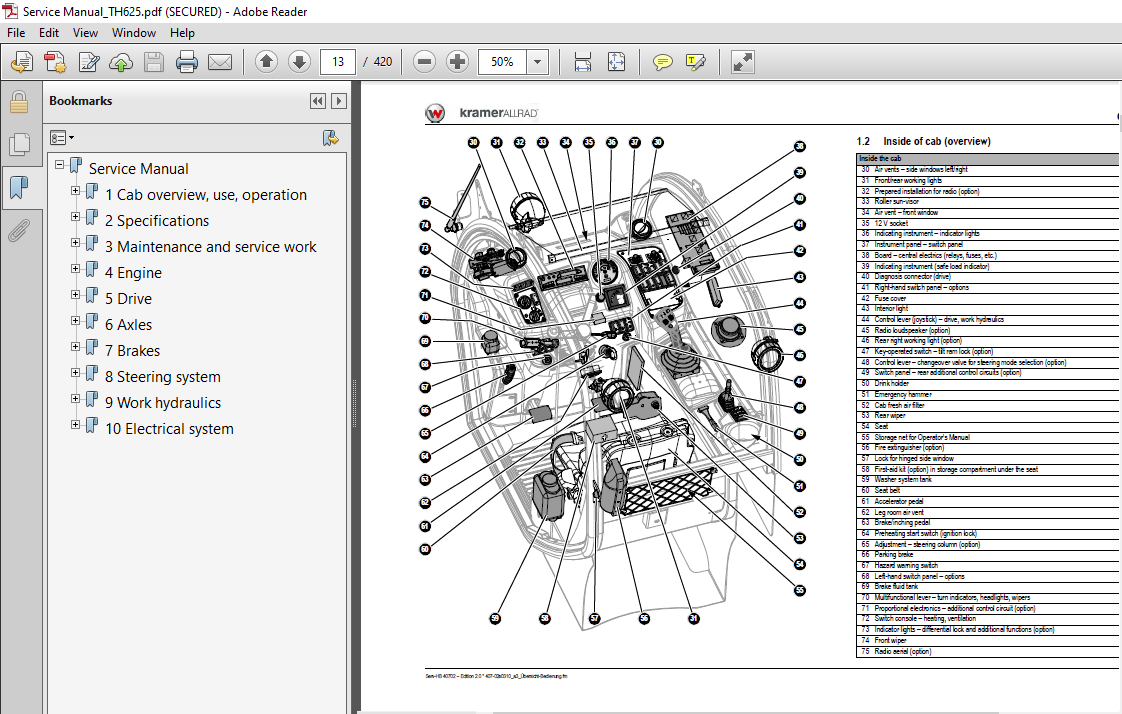
1 2 Inside of cab (overview) 1-3
1 3 Instrument panel, multifunctional lever, switch consoles (overview) 1-4
1 4 Fields of application and using a machine with an attachment 1-5
1 5 Legal regulations regarding machine operation 1-6
1 6 Type labels and component numbers 1-8
1 7 Key-based drive interlock (option) 1-11
1 8 Drive interlock with code input (option) 1-13
1 9 Battery master switch (option) 1-16
1 10 Avoiding running the engine under low-load conditions 1-17
1 11 Stopping the diesel engine 1-17
1 12 Jump-starting the diesel engine (external battery) 1-18
1 13 Pressure relief on the quickhitch couplers 1-19
1 14 Overview of steering modes (option) 1-20
1 15 Steering synchronisation (wheels front/rear axles) 1-21
1 16 Low-speed control (option) 1-23
1 17 Rear hydraulic additional control circuit (option) 1-24
1 18 Hydraulic connection for tipping trailer (option) 1-26
1 19 Autohitch trailer coupling (option) 1-27
1 20 Automatic trailer coupling (option) 1-29
1 21 Hydraulic trailer brake connection (option) 1-31
1 22 Fitting attachments from other manufacturers (option) 1-32
1 23 Towing the machine 1-35
2 Specifications
2 1 Model and trade names (overview) 2-2
2 2 Frame 2-2
2 3 Diesel engine 2-2
2 4 Drive 2-3
2 5 Axles 2-4
2 6 Service and parking brake (disc brake) 2-5
2 7 Steering system 2-5
2 8 Work hydraulics 2-6
2 9 Electrical system 2-8
2 10 Tyres 2-11
2 11 Machine weight, axle loads 2-11
2 12 Trailer couplings: trailer weight/drawbar load 2-12
2 13 Sound levels, noise 2-12
2 14 Vibrations, oscillation and acceleration values 2-13
2 15 Coolant compound table 2-13
2 16 Tightening torques 2-14
2 17 Standard bucket payloads 2-14
2 18 Pallet forks payloads 2-15
2 19 Dimensions with standard bucket 2-17
2 20 Dimensions with pallet forks 2-18
Inhaltverzeichnis
I-2 Serv-HB 40702 – Ausgabe 2 0 * 407-02s_20_enIVZ fm
Inhaltverzeichnis
3 Maintenance and service work
3 1 Explanation of symbols on the maintenance label 3-2
3 2 Maintenance label 3-3
3 3 Fluids and lubricants 3-4
3 4 Maintenance plan (overview) 3-5
3 5 Important notice regarding maintenance work 3-9
3 6 Safety strut for telescopic boom 3-10
3 7 Fuel system 3-11
3 8 Refuelling 3-12
3 9 Checking/cleaning the additional fuel filter (water separator, option) 3-12
3 10 Bleeding the fuel system 3-13
3 11 Replacing the fuel filter 3-14
3 12 Diesel engine lubrication system 3-15
3 13 Filling up engine oil 3-16
3 14 Change the engine oil 3-17
3 15 Replacing the engine oil filter cartridge 3-18
3 16 Diesel engine and hydraulics cooling system 3-19
3 17 Temperature gauge: diesel engine coolant 3-20
3 18 Filling up coolant 3-21
3 19 Cleaning the radiator fins 3-22
3 20 Draining coolant 3-23
3 21 Air filter 3-24
3 22 Replacing the filter cartridge 3-25
3 23 V-belts 3-26
3 24 Hydraulic system 3-27
3 25 Monitoring the hydraulic oil and the return filter indicator lights 3-28
3 26 Checking the hydraulic oil level once a day 3-29
3 27 Filling up hydraulic oil 3-29
3 28 Changing the filter insert 3-30
3 29 Replacing hydraulic oil 3-31
3 30 Important notices on the use of biodegradable oil 3-32
3 31 Checking hydraulic pressure lines 3-33
3 32 Oil levels: rear axle transfer gearbox 3-34
3 33 Oil levels: front and rear axle differentials 3-35
3 34 Oil levels: front and rear axle planetary drives 3-36
3 35 Lubrication work 3-37
3 36 Lubrication points on the telescopic boom (overview) 3-38
3 37 Lubricating with the central lubrication system (option) 3-40
3 38 Setting the lubrication and break times 3-41
3 39 Central lubrication system diagram 3-42
3 40 Installing the high-pressure hoses on the central lubrication system 3-43
3 41 Instructions for troubleshooting in case of central lubrication system blocking 3-44
3 42 Repairing a blocking distributor of the central lubrication system 3-45
3 43 Troubleshooting table for central lubrication system 3-46
3 44 Maintenance of the brake system 3-47
3 45 Tyres 3-48
3 46 Changing wheels 3-49
3 47 Heating/cab ventilation 3-50
3 48 Air conditioning (option): maintenance 3-51
3 49 Functional and visual checks of the air conditioning 3-52
3 50 Cleaning the heat exchanger (condenser) 3-53
3 51 Maintenance of the electrical system 3-54
3 52 Maintenance of the automatic trailer coupling (option) 3-58
3 53 General maintenance and cleaning work 3-59
3 54 Maintenance of attachments and of the work equipment 3-61
Serv-HB 40702 – Ausgabe 2 0 * 407-02s_20_enIVZ fm I-3
Inhaltverzeichnis
4 Engine
4 1 Diesel engine diagrams 4-2
4 2 Diagnosis/fuel preheater (electrical diagrams) 4-4
4 3 Manual throttle diagrams 4-6
4 4 Engine designation 4-7
4 5 Fuel specification 4-7
4 6 Coolant specification 4-7
4 7 Diesel engine TD 2009 L04 (overview) 4-8
4 8 Electric components on engine (overview) 4-9
4 9 Lube oil circuit 4-10
4 10 Cooling 4-11
4 11 Adjusting the cable pull for speed regulation 4-12
4 12 Fuel system 4-13
4 13 Replacing the cylinder head gasket 4-14
4 14 Removing/installing the fuel injection pump 4-17
4 15 Mounting the fuel injection pump 4-19
4 16 Removing/installing the fuel injectors 4-20
4 17 Sealing the coolant pump 4-21
4 18 Removing/installing the thermostat 4-21
4 19 Checking the thermostat 4-22
4 20 Assembly instructions: replacing the Visco clutch 4-23
4 21 Tightening torque table 4-26
4 22 Diesel engine malfunctions 4-28
I-4 Serv-HB 40702 – Ausgabe 2 0 * 407-02s_20_enIVZ fm
Inhaltverzeichnis
5 Drive
5 1 Drive (hydraulic diagram) 5-2
5 2 Drive diagrams 5-4
5 3 Making settings with the laptop 5-5
5 4 Error: Incorrect Tool Key 5-8
5 5 Importing new data 5-9
5 6 Drive electronics PLUS+1 mode description 5-11
5 7 Reading out/deleting the error history 5-12
5 8 Deleting the error history 5-13
5 9 Switching the inching potentiometer ON/OFF 5-14
5 10 Reading in the inching potentiometer again 5-15
5 11 Reading in the inching potentiometer 5-16
5 12 Switching the creep gear potentiometer ON/OFF 5-17
5 13 Switching ON the creep gear potentiometer 5-18
5 14 Reading in the creep gear potentiometer 5-19
5 15 Modifying the load stabiliser settings 5-20
5 16 Error code table 5-21
5 17 Towing and transporting the machine 5-23
5 18 Hydraulic pump H1 (model 407 02) test ports and HP valves (overview) 5-23
5 19 Hydraulic pump H1 (model 407 02) proportional valve and electronics
(overview) 5-24
5 20 Variable displacement motor H1 110 cm3/rev (overview) 5-25
5 21 Variable displacement motor H1B (overview) 5-26
5 22 Model 407 02 test report 5-27
5 23 Error description for test report model 407 02 5-28
5 24 Drive with hydraulic pump H1 (hydraulic circuit) 5-29
5 25 Checking the idling speed 5-30
5 26 Checking/adjusting starting speed 5-31
5 27 Adjusting boost pressure 5-32
5 28 Checking high pressure 5-33
5 29 Checking driving direction identification 5-34
5 30 Checking the energisation of the driving direction identification 5-35
5 31 Checking engine droop (variable displacement pump) 5-36
5 32 Setting the pump droop speed 5-37
5 33 Setting engine droop/control initiation of the hydraulic motor 5-38
5 34 Setting maximum speed 5-39
5 35 Troubleshooting boost-pressure errors (diagram) 5-40
5 36 Checking high pressure (HP valves) 5-41
5 37 Checking pump engine droop, driving direction identification, differential pressure measurement 5-42
6 Axles
6 1 Differential lock diagrams 6-2
6 2 Axle type label 6-3
6 3 Front axle screw connections 6-4
6 4 Rear axle screw connections 6-5
6 5 Drain, fill and check plug – front axle 6-6
6 6 Drain, fill and check plug – rear axle 6-7
6 7 Front axle tightening torques (Nm) 6-8
6 8 Rear axle tightening torques (Nm) 6-9
6 9 Sealing work 6-10
Serv-HB 40702 – Ausgabe 2 0 * 407-02s_20_enIVZ fm I-5
Inhaltverzeichnis
7 Brakes
7 1 Brake diagrams 7-2
7 2 Brakes (hydraulic diagram) 7-4
7 3 Brake circuit 7-5
7 4 Trailer brake valve circuit 7-6
7 5 Service brake function 7-7
7 6 Parking brake circuit 7-8
7 7 Service brake 7-9
7 8 Sealing the brake calliper 7-10
7 9 Bleeding the brake system with bleed equipment 7-12
7 10 Setting the brake pedal with the inching potentiometer 7-13
8 Steering system
8 1 Steering system (hydraulic diagram) 8-2
8 2 Steering circuit with final-position synchronisation 8-3
8 3 Steering circuit with front, 4 wheel and crab steering 8-4
8 4 Steering system adjustment 8-5
8 5 Hydraulic ports on servostat 8-5
8 6 Pressure relief valve: adjustment 8-5
8 7 Sealing steering rams 8-6
8 8 Sealing steering rams 8-7
8 9 Checking the steering mode valve 8-8
8 10 Checking a steering ram 8-9
8 11 Overview of steering ram setting 8-9
8 12 How to check and set the steering rams 8-10
8 13 Checking the track setting (1) 8-11
8 14 Correcting the track setting (2) 8-11
8 15 Steering misalignment during final-position synchronisation (3) 8-12
8 16 Adjustment work 8-13
8 17 Checking steering synchronisation (4) 8-14
I-6 Serv-HB 40702 – Ausgabe 2 0 * 407-02s_20_enIVZ fm
Inhaltverzeichnis
9 Work hydraulics
9 1 20 kph 4-fold control valve (hydraulic diagram) 9-2
9 2 30 kph 5-fold control valve (hydraulic diagram) 9-4
9 3 Hydraulics legend 9-5
9 4 Raising/lowering (diagrams) 9-8
9 5 Raising/lowering the telescopic boom (hydraulic diagram) 9-10
9 6 Raising/lowering the telescopic boom, load stabiliser (hydraulic diagram) 9-12
9 7 Dumping in/out, tilt ram lock (electrical diagrams) 9-14
9 8 Dumping out (hydraulic diagram) 9-16
9 9 Tilt ram lock (hydraulic diagram) 9-18
9 10 Extending/retracting the telescopic boom (black/white) (electrical diagrams) 9-20
9 11 Extending/retracting the telescopic boom/proportional (electrical diagrams) 9-22
9 12 Retracting/extending the telescopic boom (hydraulic diagram) 9-24
9 13 Locking/unlocking the quickhitch (black/white) (electrical diagrams) 9-26
9 14 Quickhitch diagram designations (black/white, lock/unlock) 9-27
9 15 Locking/unlocking the quickhitch proportionally (electrical diagrams) 9-30
9 16 Quickhitch diagram designations (proportional, lock/unlock) 9-31
9 17 Locking (hydraulic diagram) 9-34
9 18 Locking/additional control circuit (hydraulic diagram) 9-36
9 19 Locking/return without pressure (hydraulic diagram) 9-38
9 20 Safe load indicator (electrical diagrams) 9-40
9 21 Overload cutoff (hydraulic diagram) 9-42
9 22 Load stabiliser (electrical diagrams) 9-44
9 23 Additional control circuit/tipping trailer (hydraulic diagram) 9-46
9 24 Tipping trailer (hydraulic diagram) 9-48
9 25 Autohitch (hydraulic diagram) 9-50
9 26 Autohitch/tipping trailer (hydraulic diagram) 9-52
9 27 Additional function (electrical diagrams) 9-54
9 28 Autohitch/additional control circuit/tipping trailer (hydraulic diagram) 9-56
9 29 Test report for hydraulics 407-02 (2506) 9-57
9 30 Work hydraulics oil supply 9-58
9 31 Pump pressure/work hydraulics test port 9-59
9 32 Control valve (overview) 9-60
9 33 Control valve design 9-61
9 34 Checking and setting the work hydraulics 9-62
9 35 7-fold pilot valve (overview) 9-63
9 36 4-fold pilot valve (overview) 9-64
9 37 Pilot control circuit 9-65
9 38 Load stabiliser circuit 9-66
9 39 Lift ram circuit 9-67
9 40 Tilt ram circuit 9-68
9 41 3rd control circuit 9-69
9 42 Circuit: additional control circuít and rear tipping trailer 9-70
9 43 Tilt ram lock circuit 9-71
9 44 Circuit: Autohitch and tipping trailer ports 9-72
9 45 Overload cutoff circuit 9-73
9 46 Load stabiliser 9-74
9 47 Valve for tilt ram lock 9-76
9 48 Tipping trailer and additional control circuit valve 9-76
9 49 Work hydraulics/steering system priority valve 9-77
9 50 Valves (general overview) 9-77
9 51 Lift ram (sealing work) 9-78
9 52 Tilt ram (sealing work) 9-79
9 53 Push-out ram 9-80
9 54 Compensating ram 9-81
9 55 Control ram (quickhitch frame) (sealing work) 9-82
9 56 Lift, tilt and push-out rams: velocity 9-83
Serv-HB 40702 – Ausgabe 2 0 * 407-02s_20_enIVZ fm I-7
Inhaltverzeichnis
9 57 Usable consumer pressure at additional control circuit (option) 9-83
9 58 Overload control (“Smart Handling”) 9-84
9 59 Overview of safe load indicator 9-90
9 60 Setting the safe load indicator (0 % point) 9-90
9 61 Setting the safe load indicator (100 % point stability) 9-91
9 62 Inspection plan for overload control (model 407 telehandler) 9-93
9 63 Testing without any load 9-93
9 64 Testing with load 9-95
9 65 Functional description of overload control (Smart Handling) 9-97
9 66 Electric components 9-98
9 67 Circuit diagram: overload control enabled 9-99
9 68 Circuit diagram: automatic retraction OFF 9-100
9 69 Overview of valves 9-101
9 70 Overview of valve connections and ports 9-101
9 71 Circuit diagram: overload control 9-102
9 72 Circuit diagram legend 9-103
9 73 Extend (solenoid valve Y102) (circuit diagram) 9-104
9 74 Pallet forks mode (circuit diagram) 9-105
9 75 Tip switch S084 pressed (circuit diagram) 9-106
9 76 Electric components 9-107
9 77 Overload control relay 9-108
9 78 Installation position: overload control relay 9-109
I-8 Serv-HB 40702 – Ausgabe 2 0 * 407-02s_20_enIVZ fm
Inhaltverzeichnis
10 Electrical system
10 1 Lights (diagrams) 10-2
10 2 Working lights (diagrams) 10-4
10 3 Turn indicators/horn/rotating beacon (diagrams) 10-6
10 4 Window heating/front socket (electrical diagrams) 10-8
10 5 Wipe/wash system (electrical diagrams) 10-10
10 6 Seat/air conditioning system (diagrams) 10-12
10 7 Multimedia/monitoring/cigarette lighter (electrical diagrams) 10-14
10 8 Cab wiring harness 1000256306-01 10-16
10 9 Cab wiring harness legend 10-17
10 10 Engine wiring harness 1000245802 10-22
10 11 Engine wiring harness legend 10-23
10 12 Frame wiring harness 1000256307 10-26
10 13 Frame wiring harness (legend) 10-27
10 14 Cab wiring harness (overload control) 10-30
10 15 Cab wiring harness legend 10-31
10 15 Frame wiring harness (overload control) 10-34
10 16 Frame wiring harness (overload control) (legend) 10-35
10 17 Ohm’s Law (current, voltage, resistance); power 10-36
10 18 Measuring equipment, measuring methods 10-36
10 19 Terminal description 10-37
10 20 Colour coding of electric lines 10-41
10 21 Switching relay function 10-43
10 22 Fuse assignment 10-44
10 23 Switching relay assignment on board 10-45
10 24 Switching relay assignment on bracket 10-45
10 25 Main fuse box with relays in the engine compartment 10-46
10 26 Electric units 10-46
10 27 Connector description (overview) 10-46
10 28 Switch assignment on board (overview) 10-47
10 29 Switch assignment on instrument panel (overview) 10-48
10 30 Control lever (black/white control) 10-49
10 31 Joystick (black/white function) 10-50
10 32 Joystick: retracting/extending the telescopic boom (black/white) 10-51
10 33 Joystick: unlocking/locking the telescopic boom (black/white) 10-52
10 34 Control lever (proportional control) 10-53
10 35 Joystick (proportional function) 10-54
10 36 Joystick: retracting/extending the telescopic boom (proportional) 10-55
10 37 Joystick: unlocking/locking the telescopic boom (proportional) 10-56
10 38 Additional control circuit with potentiometer (proportional) 10-57
10 39 Proportional controls connector assignment (overview) 10-58
10 40 Proportional controls (overview and connections) 10-58
10 41 Retrofitting a rotating beacon 10-59
10 42 Retrofitting the backup warning system 10-59
10 43 Retrofitting 2 front working lights 10-59
10 44 Retrofitting 2 rear working lights 10-60
10 45 Retrofitting a rear 7-pole socket 10-60
10 46 Retrofitting a front 4-pole socket 10-60
10 47 Retrofitting 2 working lights on the telescopic boom (from mid 2011) 10-61
IMAGES PREVIEW OF THE MANUAL: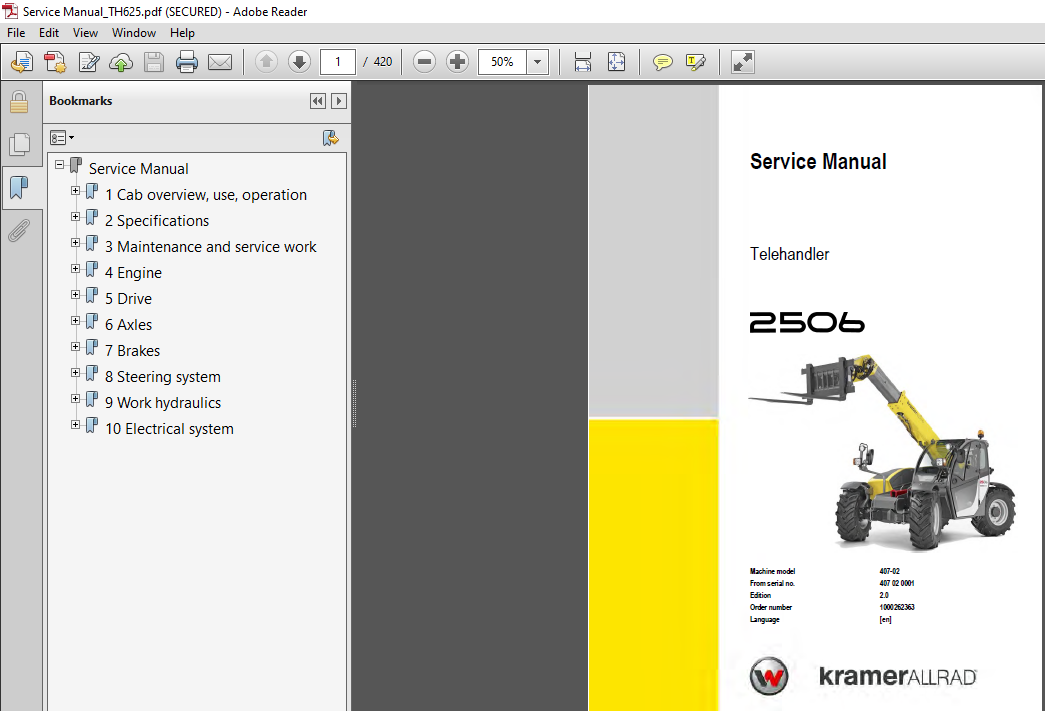
More products