$36
Kubota LM2605 Front Loader Workshop Manual – PDF DOWNLOAD
Kubota LM2605 Front Loader Workshop Manual – PDF DOWNLOAD
FILE DETAILS:
Kubota LM2605 Front Loader Workshop Manual – PDF DOWNLOAD
Language : English
Pages : 184
Downloadable : Yes
File Type : PDF
Size: 62.9 MB
IMAGES PREVIEW OF THE MANUAL:
DESCRIPTION:
Kubota LM2605 Front Loader Workshop Manual – PDF DOWNLOAD
TO THE READER:
This workshop manual provides safety information for service activity, general information such as specifications and
dimensions of the machine, mechanisms and structure descriptions of the machine, and service procedures.
Safety
This section contains safety service descriptions and safety label information.
General
This section contains general instructions, tightening torques, general machine information and special tools.
Maintenance
This section contains information for the recommended oil and general maintenance procedures.
Each section basically consists of mechanism and servicing.
Mechanism
Mechanism part contains information and explanations for the structure, functions, and specifications of the machine
or component parts. This part should be comprehended before proceeding with troubleshooting, disassembling,
assembling, and servicing works.
Servicing
Servicing part contains information and procedures for maintenance, troubleshooting and repair works. The reader
should follow these instructions in order to satisfy any servicing work safely, correctly and quickly.
In this WSM, service specifications and service limits are defined as followings.
Service specifications:
Specification which corresponds to new machine’s ex-factory. It is based on quality standard, drawings, or actual
measurements conducted by Kubota. This value is used to determine whether there is a problem with the machine in
the event of a troubleshooting. However, it is necessary to consider degradation due to wear, based on the operating
time of the machine, application or maintenance condition.
Service limits:
Service limit is a value corresponding to the recommended performance limit by taking long term-use wear into
account. When the service limit is reached , the machine is required to have proper repair, overhaul or replacement in
order to keep safe and adequate performance.
All of the illustrations, photographs, specifications, and other information in this manual were created based on the
latest model at the time of publication.
The parts names used in this manual are unified into names representing the functions of the parts. Therefore, it does
not necessarily correspond to the names used in other materials (parts list, operators manual etc.) and the name on
the label/ identification plates on the product.
Kubota reserves the right to change all information at any time without notice.
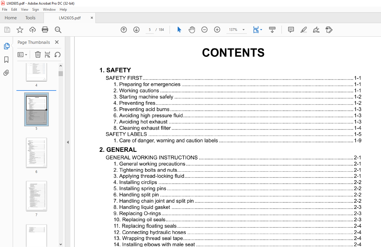
TABLE OF CONTENTS:
Kubota LM2605 Front Loader Workshop Manual – PDF DOWNLOAD
1 SAFETY
SAFETY FIRST 1-1
1 Preparing for emergencies 1-1
2 Working cautions 1-1
3 Starting machine safely 1-2
4 Preventing fires 1-2
5 Preventing acid burns 1-3
6 Avoiding high pressure fluid 1-3
7 Avoiding hot exhaust 1-3
8 Cleaning exhaust filter 1-4
SAFETY LABELS 1-5
1 Care of danger, warning and caution labels 1-9
2 GENERAL
GENERAL WORKING INSTRUCTIONS 2-1
1 General working precautions 2-1
2 Tightening bolts and nuts 2-1
3 Applying thread-locking fluid 2-1
4 Installing circlips 2-2
5 Installing spring pins 2-2
6 Handling split pin 2-2
7 Handling chain joint and split pin 2-2
8 Handling liquid gasket 2-3
9 Replacing O-rings 2-3
10 Replacing oil seals 2-3
11 Replacing floating seals 2-4
12 Connecting hydraulic hoses 2-4
13 Wrapping thread seal tape 2-4
14 Installing elbows with male seat 2-4
15 Connecting and disconnecting quick hose couplings 2-5
16 Handling the battery 2-5
17 Handling wire harness 2-5
18 Handling fuses 2-7
19 Handling connectors 2-7
20 Wiring color 2-8
21 Washing the machine with a high pressure washer 2-8
22 Dispose fluids correctly 2-9
TIGHTENING TORQUES 2-11
1 General use screws, bolts and nuts 2-11
2 Stud bolts 2-12
3 Hydraulic fitting 2-13
3 1 Hydraulic hose fittings 2-13
3 2 Hydraulic pipe cap nuts 2-13
3 3 Adapters, elbows, and others 2-14
4 Metric screws, bolts and nuts 2-15
5 American standard screws, bolts and nuts with UNC or UNF threads 2-15
6 Plugs 2-15
IDENTIFICATION 2-17
1 Outline of loader identification 2-17
SPECIFICATIONS 2-19
1 Suitable tractor 2-19
2 Specifications for loader 2-19
3 Specifications for bucket 2-19
4 Dimensional specifications 2-20
LM2605 iii
KiSC issued 01 , 2022 A
5 Operational specifications 2-21
TERMINOLOGY 2-23
1 Loader terminology 2-23
SPECIAL TOOLS 2-25
1 Special tools for loader 2-25
1 1 Release Tool (1/2 SCH) 2-25
1 2 Release Tool (3/8 SCH) 2-25
3 MAINTENANCE
MAINTENANCE CHECKLIST 3-1
LUBRICANTS 3-3
CHECK AND MAINTENANCE 3-5
1 Daily check 3-5
1 1 Checking the transmission fluid 3-5
1 2 Checking hydraulic hoses 3-5
1 3 Checking and tightening the loose bolts and the nuts 3-6
1 4 Checking quick attach coupler 3-6
2 Service every 10 hours 3-6
2 1 Lubricating the loader 3-6
3 Service every 20 hours to 30 hours 3-7
3 1 Re-tightening of hardware 3-7
4 Check point of every 50 hours 3-7
4 1 Checking all mounting bolts torque 3-7
4 2 Others 3-7
4 FRONT LOADER
MECHANISM 4-1
1 Hydraulic system 4-1
1 1 Open center model 4-1
1 1 1 Structure of hydraulic system 4-1
1 1 2 Feature of hydraulic system 4-3
1 1 3 Oil flow of hydraulic system 4-3
1 1 4 Control valve 4-4
1 2 Closed center with load sensing model 4-20
1 2 1 Structure of hydraulic system 4-20
1 2 2 Feature of hydraulic system 4-21
1 2 3 Oil flow of hydraulic system 4-21
1 2 4 Control valve 4-22
1 3 Selectable valve 4-38
1 3 1 Structure of selectable valve 4-38
1 3 2 Function of selectable valve 4-40
1 4 3rd function valve assembly 4-44
1 4 1 3rd function valve assembly (Open center model) 4-44
1 4 2 3rd function valve assembly (Closed center with load sensing model) 4-50
1 5 Hydraulic accumulator 4-56
1 5 1 Outline of hydraulic accumulator 4-56
1 5 2 Structure of hydraulic accumulator 4-57
1 5 3 Function of hydraulic accumulator 4-58
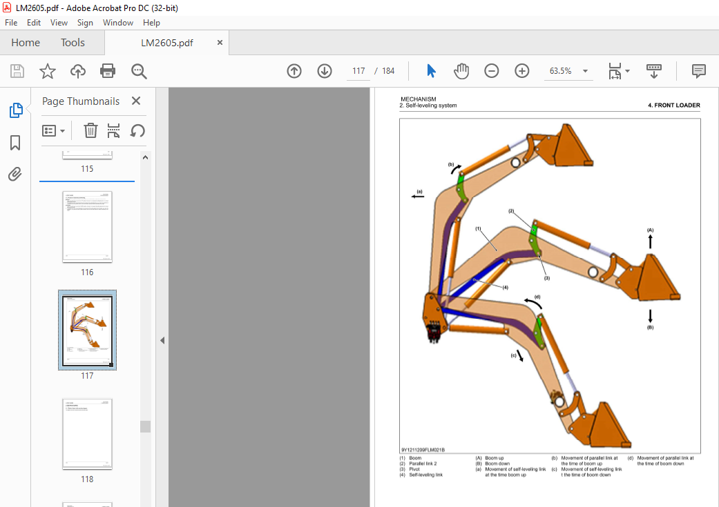
2 Self-leveling system 4-59
2 1 Mechanical self-leveling 4-59
2 1 1 Structure of mechanical self-leveling 4-59
2 1 2 Function of mechanical self-leveling 4-60
3 Electrical system 4-62
3 1 Open center model 4-62
3 1 1 Outline of open center electrical diagram 4-62
3 1 2 Structure of open center electrical circuit 4-64
3 1 3 Flow of open center electrical current 4-64
3 2 Closed center load sensing model 4-65
iv LM2605
KiSC issued 01 , 2022 A
3 2 1 Outline of closed center electrical diagram 4-65
3 2 2 Structure of closed center electrical circuit 4-66
3 2 3 Flow of closed center electrical current 4-66
3 3 Location of joint connector 4-66
3 3 1 X59 joint connector 4-66
3 3 2 X17 joint connector 4-66
3 3 3 X56 joint connector 4-67
3 3 4 Main valve lower connector 4-67
3 3 5 Main valve upper connector 4-67
SERVICING 4-69
1 Troubleshooting for front loader 4-69
2 Service specifications for front loader 4-78
3 Tightening torques for front loader 4-84
4 Checking and adjusting 4-85
4 1 Checking control valve 4-85
4 1 1 Checking relief valve setting pressure 4-85
4 1 2 Checking control valve solenoid ( closed center model control valve) 4-85
4 2 Checking 3rd function valve 4-86
4 2 1 Checking 3rd function valve for open center model 4-87
4 2 2 Checking 3rd function valve for closed center model 4-87
4 3 Checking selectable valve 4-88
4 3 1 Checking accumulator solenoid valve 4-88
4 3 2 Checking 4th function solenoid valve 4-88
4 4 Checking relay and switch 4-89
4 4 1 Checking voltage of relay (open center model) 4-89
4 4 2 Checking continuity of relay (open center model) 4-90
4 4 3 Checking voltage of accumulator switch (open center model) 4-90
4 4 4 Checking resistance of accumulator switch (open center model) 4-91
4 4 5 Checking voltage of activation switch (open center model) 4-91
4 4 6 Checking resistance of activation switch (open center model) 4-92
4 4 7 Checking voltage of ON-OFF switch (open center model) 4-92
4 4 8 Checking resistance of ON-OFF switch (open center model) 4-93
5 Disassembling and assembling 4-93
5 1 Removing the loader 4-93
5 1 1 How to remove the loader 4-93
5 2 Reinstalling the loader 4-95
5 2 1 How to reinstall the loader 4-95
5 3 Removing open center model control valve 4-96
5 3 1 Removing control cable from control valve 4-96
5 3 2 Removing control valve 4-97
5 4 Disassembling control valve 4-98
5 5 Removing closed center model control valve 4-101
5 5 1 Removing hydraulic and electric lines from control valve 4-101
5 6 Disassembling control valve 4-102
5 7 Removing and disassembling control lever (Open center model) 4-105
5 7 1 Removing wire harness 4-105
5 7 2 Disassembling control lever 4-105
5 8 Removing and disassembling 3rd function valve 4-106
5 8 1 Removing 3rd function valve 4-106
5 8 2 Disassembling 3rd function valve 4-107
5 9 Removing and disassembling selectable valve 4-108
5 9 1 Removing hydraulic hose 4-108
5 9 2 Removing hydraulic accumulator 4-109
5 9 3 Removing selectable valve 4-110
5 9 4 Disassembling 4th function valve 4-111
5 10 Removing front end quick coupler 4-111
5 11 Removing bucket 4-112
5 11 1 Removing bucket (euro quick coupler type) 4-112
LM2605 V
KiSC issued 01 , 2022 A
vi
5 12 Removing hydraulic line 4-113
5 12 1 Removing hydraulic line from boom 4-113
5 13 Removing boom cylinder 4-114
5 14 Removing quick hitch 4-115
5 14 1 Removing quick hitch 4-115
5 14 2 Disassembling quick hitch 4-116
5 15 Removing bucket cylinder 4-116
5 16 Removing side frame 4-117
5 17 Removing parallel link 4-118
5 18 Removing main frame 4-119
5 19 Removing front guard 4-119
6 Servicing 4-121
6 1 DTC (diagnostic trouble code) list 4-121
More products