$34
Kubota Tractor B2301 B2601 Workshop Manual – PDF DOWNLOAD
Kubota Tractor B2301 B2601 Workshop Manual – PDF DOWNLOAD
FILE DETAILS:
Kubota Tractor B2301 B2601 Workshop Manual – PDF DOWNLOAD
Language : English
Pages : 341
Downloadable : Yes
File Type : PDF
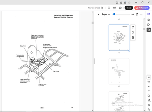
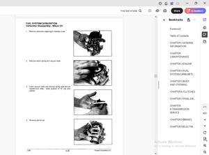
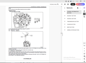
IMAGES PREVIEW OF THE MANUAL:
DESCRIPTION:
Kubota Tractor B2301 B2601 Workshop Manual – PDF DOWNLOAD
TO THE READER:
This Workshop Manual tells the servicing personnel about the mechanism, servicing and
maintenance of the B2301 and B2601. It contains 4 parts: “Information”, “General”, “Mechanism”
and “Servicing”.
Information
This section primarily contains information below.
• Safety First
• Safety Decal
• Specifications
• Dimensions
General
This section primarily contains information below.
• Engine Identification
• Model Identification
• General Precautions
• Maintenance Check List
• Check and Maintenance
• Special Tools
Mechanism
This section contains information on the structure and the function of the unit. Before you continue
with the subsequent sections, make sure that you read this section.
Refer to the latest version of Workshop Manual (Code No. 9Y021-01870 / 9Y021-18200) for the
diesel engine / tractor mechanism that this workshop manual does not include.
Servicing
This section primarily contains information below.
• Troubleshooting
• Servicing Specifications
• Tightening Torques
• Checking, Disassembling and Servicing
All illustrations, photographs and specifications contained in this manual are of the newest
information available at the time of publication.
KUBOTA reserves the right to change all information at any time without notice.
Since this manual includes many models, information or illustrations and photographs can show
more than one model.
TABLE OF CONTENTS:
Kubota Tractor B2301 B2601 Workshop Manual – PDF DOWNLOAD
I INFORMATION..................................................................  3
	1. SAFETY FIRST............................................................  5
	2. SAFETY DECALS...........................................................  8
	3. SPECIFICATIONS.......................................................... 11
	4. TRAVELING SPEEDS........................................................ 12
G GENERAL...................................................................... 14
	1. TRACTOR IDENTIFICATION.................................................. 16
	2. GENERAL PRECAUTIONS..................................................... 17
	3. HANDLING PRECAUTIONS FOR ELECTRICALPARTS AND WIRING..................... 18
	4. LUBRICANTS, FUEL AND COOLANT............................................ 23
	5. TIGHTENING TORQUES...................................................... 26
	6. MAINTENANCE CHECK LIST.................................................. 28
	7. CHECK AND MAINTENANCE................................................... 30
	8. SPECIAL TOOLS........................................................... 50
	9. TIRES................................................................... 60
	10. IMPLEMENT LIMITATIONS.................................................. 67
1 ENGINE....................................................................... 69
	MECHANISM.................................................................. 70
		1. ENGINE BODY......................................................... 71
			[1] CLOSED BREATHER................................................ 71
			[2] GOVERNOR....................................................... 72
	SERVICING.................................................................. 74
		1. TROUBLESHOOTING..................................................... 75
		2. SERVICING SPECIFICATIONS............................................ 79
		3. TIGHTENING TORQUES.................................................. 85
			[1] TRACTOR SECTION................................................ 85
			[2] ENGINE SECTION................................................. 85
		4. CHECKING, DISASSEMBLING AND SERVICING............................... 86
			[1] CHECKING AND ADJUSTING......................................... 86
				(1) Engine Body................................................ 86
				(2) Lubricating System......................................... 88
				(3) Cooling System............................................. 88
				(4) Fuel System................................................ 91
			[2] PREPARATION.................................................... 95
				(1) Draining Lubricants and Coolant............................ 95
				(2) Separating Engine from Clutch Housing...................... 97
				(3) Separating Engine from Front Axle Frame.................... 98
			[3] DISASSEMBLING AND ASSEMBLING................................... 99
				(1) External Components........................................ 99
				(2) Cylinder Head and Valve and Oil Pan........................ 99
				(3) Gear Case..................................................102
				(4) Piston and Connecting Rod..................................106
				(5) Crankshaft.................................................109
			[4] SERVICING......................................................111
				(1) Cylinder Head and Valves...................................111
				(2) Idle Gear and Camshaft.....................................116
				(3) Piston and Connecting Rod..................................118
				(4) Crankshaft.................................................121
				(5) Cylinder...................................................125
2 TRANSMISSION.................................................................127
	MECHANISM..................................................................128
		1. STRUCTURE...........................................................129
		2. FRONT CASE..........................................................130
		3. HYDROSTATIC TRANSMISSION............................................131
			[1] STRUCTURE......................................................131
			[2] PUMP AND MOTOR.................................................133
			[3] OIL FLOW AND VALVES............................................134
			[4] CONTROL LINKAGE................................................141
		4. SPEED SET DEVICE....................................................142
			[1] SPEED SET LINKAGE..............................................142
				(1) Speed Set..................................................142
				(2) Speed Set Release..........................................143
		5. RANGE GEAR SHIFT SECTION............................................144
		6. FRONT WHEEL DRIVE SECTION...........................................145
		7. PTO SYSTEM..........................................................146
			[1] STRUCTURE......................................................146
			[2] REAR PTO SECTION...............................................147
			[3] REAR PTO / MID-PTO SECTION.....................................148
			[4] MID-PTO SECTION................................................149
			[5] INDEPENDENT PTO................................................150
				(1) Hydraulic Circuit..........................................150
				(2) Independent PTO Control Valve..............................150
				(3) Independent PTO Clutch.....................................151
				(4) Independent PTO Lever "Engaged"............................152
				(5) Independent PTO Lever "Disengaged".........................153
		8. DIFFERENTIAL GEAR SYSTEM............................................154
			[1] DIFFERENTIAL FUNCTION..........................................154
			[2] DIFFERENTIAL LOCK..............................................155
	SERVICING..................................................................156
		1. TROUBLESHOOTING.....................................................157
		2. SERVICING SPECIFICATIONS............................................161
		3. TIGHTENING TORQUES..................................................163
		4. CHECKING, DISASSEMBLING AND SERVICING...............................164
			[1] CHECKING AND ADJUSTING.........................................164
				(1) HST........................................................164
				(2) Independent PTO Control Valve..............................169
			[2] PREPARATION....................................................170
				(1) Dismounting the Step and Floor Seat........................170
			[3] DISASSEMBLING AND ASSEMBLING...................................176
				(1) Separating Engine and Clutch Housing.......................176
				(2) Front Case.................................................176
				(3) Hydraulic Transmission (HST)...............................177
				(4) PTO Clutch Case............................................181
				(5) Bevel Pinion Shaft.........................................181
				(6) Sub Gear Shaft.............................................182
				(7) Front Wheel Drive Shaft....................................183
				(8) Independent PTO Clutch Shifter.............................185
				(9) Independent PTO Clutch.....................................186
				(10) Mid-PTO Section...........................................190
				(11) Differential Gear Section.................................192
			[4] SERVICING......................................................194
				(1) HST........................................................194
				(2) Independent PTO Clutch.....................................196
				(3) Transmission Case..........................................197
				(4) Differential Gear..........................................198
3 REAR AXLE....................................................................201
	MECHANISM..................................................................202
		1. STRUCTURE...........................................................203
	SERVICING..................................................................204
		1. TROUBLESHOOTING.....................................................205
		2. TIGHTENING TORQUES..................................................206
		3. DIASSEMBLING AND SERVICING..........................................207
			[1] DIASSEMBLING AND ASSEMBLING....................................207
				(1) Separating Rear Axle Case..................................207
				(2) Disassembling Rear Axle Case...............................208
			[2] SERVICING......................................................209
4 BRAKES.......................................................................210
	MECHANISM..................................................................211
		1. LINKAGE.............................................................212
		2. OPERATION...........................................................213
	SERVICING..................................................................214
		1. TROUBLESHOOTING.....................................................215
		2. SERVICING SPECIFICATIONS............................................216
		3. TIGHTENING TORQUES..................................................217
		4. CHECKING, DISASSEMBLING AND SERVICING...............................218
			[1] CHECKING AND ADJUSTINGAdjusting................................218
			[2] DISASSEMBLING AND ASSEMBLING...................................218
				(1) Separating Rear Axle Case..................................219
				(2) Disassembling Rear Axle Case...............................220
			[3] SERVICING......................................................221
5 FRONT AXLE...................................................................223
	MECHANISM..................................................................224
		1. STRUCTURE...........................................................225
			[1] 4 WHEEL DRIVE MODEL............................................225
	SERVICING..................................................................226
		1. TROUBLESHOOTING.....................................................227
		2. SERVICING SPECIFICATIONS............................................228
		3. TIGHTENING TORQUES..................................................229
		4. CHECKING, DISASSEMBLING AND SERVICING...............................230
			[1] CHECKING AND ADJUSTING.........................................230
			[2] DISASSEMBLING AND ASSEMBLING...................................231
				(1) Separating Front Axle Assembly.............................231
				(2) Disassembling Front Axle Assembly..........................232
			[3] SERVICING......................................................238
6 STEERING.....................................................................242
	MECHANISM..................................................................243
		1. HYDRAULIC CIRCUIT...................................................244
		2. STEERING CONTROLLER.................................................245
		3. STEERING CYLINDER...................................................246
		4. HYDRAULIC PUMP......................................................247
	SERVICING..................................................................248
		1. TROUBLESHOOTING.....................................................249
		2. SERVICING SPECIFICATIONS............................................251
		3. TIGHTENING TORQUES..................................................252
		4. CHECKING, DISASSEMBLING AND SERVICING...............................253
			[1] CHECKING.......................................................253
				(1) Relief Valve...............................................253
				(2) Hydraulic Pump for Power Steering..........................253
			[2] DISASSEMBLING..................................................254
				(1) Separating Power Steering Controller.......................254
				(2) Power Steering Controller..................................254
				(3) Power Steering Cylinder....................................255
			[3] SERVICING......................................................257
				(1) Power Steering Cylinder....................................257
7 HYDRAULIC SYSTEM.............................................................258
	MECHANISM..................................................................259
		1. HYDRAULIC CIRCUIT...................................................260
		2. HYDRAULIC PUMP......................................................261
		3. HYDRAULIC CIRCUIT...................................................262
			[1] HYDRAULIC CIRCUIT..............................................262
			[2] RELIEF VALVE...................................................263
			[3] POSITION CONTROL VALVE.........................................264
				(1) Structure..................................................264
				(2) Operation..................................................265
			[4] FEEDBACK LINKAGE FOR POSITION CONTROL..........................267
		4. FRONT LOADER CONTROL VALVE..........................................268
			[1] STRUCTURE......................................................268
			[2] OPERATION......................................................269
		5. REMOTE CONTROL VALVE (IF EQUIPPED)..................................276
		6. HYDRAULIC OUTLET....................................................277
	SERVICING..................................................................278
		1. TROUBLESHOOTING.....................................................279
		2. SERVICING SPECIFICATIONS............................................280
		3. TIGHTENING TORQUES..................................................281
		4. CHECKING, DISASSEMBLING AND SERVICING...............................282
			[1] CHECKING AND ADJUSTING.........................................282
				(1) Hydraulic Pump (For 3-Point Hitch Hydraulic System)........282
				(2) Hydraulic Pump (For Power Steering, PTO Clutch and HST)....284
				(3) 3-Points Hitch Relief Valve................................286
				(4) Lift Arm...................................................286
			[2] DISASSEMBLING AND ASSEMBLING...................................287
				(1) Hydraulic Pump.............................................287
				(2) 3-Point Hitch..............................................288
				(3) Separating Hydraulic Cylinder From Tractor Body............288
				(4) 3-Points Hitch: Hydraulic Cylinder.........................290
				(5) Front Loader Control Valve Assembly (If Equipped)..........293
				(6) Remote Control Valve (If Equipped).........................296
8 ELECTRICAL SYSTEM............................................................298
	MECHANISM..................................................................299
		1. WIRING DIAGRAM......................................................300
		2. ENGINE STARTING SYSTEM AND STOPPINGSYSTEM...........................301
			[1] OPC SYSTEM CIRCUIT.............................................301
			[2] CONTROLLER.....................................................302
			[3] SAFETY SWITCH..................................................305
				(1) PTO Select Lever Switch....................................305
				(2) PTO Clutch Lever Switch....................................305
				(3) HST Pedal Switch (HST Model)...............................306
				(4) Seat Switch................................................306
			[4] STARTER........................................................307
			[5] ENGINE STOP SOLENOID...........................................307
			[6] GLOW PLUG......................................................308
		3. CHARGING SYSTEM.....................................................309
		4. LIGHTING SYSTEM.....................................................310
			[1] HEAD LIGHT.....................................................310
			[2] TURN SIGNAL LIGHT..............................................310
			8-M12[3] HAZARD LIGHT..............................................311
		5. INSTRUMENT PANEL....................................................312
			[1] EASY CHECKER™..................................................312
			[2] SWITCHES AND SENSORS...........................................312
	SERVICING..................................................................314
		1. TROUBLESHOOTING.....................................................315
		2. SERVICING SPECIFICATIONS............................................322
		3. TIGHTENING TORQUES..................................................323
		4. CHECKING AND ADJUSTING..............................................324
			[1] BATTERY........................................................324
			[2] FUSE...........................................................325
			[3] RELAYS.........................................................326
				(1) Relays.....................................................326
			[4] STARTING SYSTEM................................................327
				(1) Key Switch.................................................327
				(2) Safety Switches............................................328
				(3) OPC Controller.............................................329
				(4) Engine Stop Solenoid.......................................329
				(5) Starter....................................................329
				(6) Glow Plug..................................................330
			[5] CHARGING SYSTEM................................................331
				(1) AC Dynamo..................................................331
				(2) Regulator..................................................331
			[6] LIGHTING SYSTEM................................................332
				(1) Combination Switch.........................................332
				(2) Flasher Unit...............................................334
			[7] WARNING LAMP, INDICATOR LAMP AND GAUGE.........................334
				(1) Instrument Panel...........................................334
				(2) Engine Oil Pressure Switch.................................335
				(3) Coolant Temperature Sensor.................................335
				(4) Fuel Sensor................................................336
		5. DISASSEMBLING AND ASSEMBLING........................................337
			[1] STARTER........................................................337
			[2] AC DYNAMO......................................................338
		6. SERVICING...........................................................339
			[1] STARTER........................................................339
More products