$35
Kubota Tractor L185 L245 L295 Workshop Manual EN_FR – PDF DOWNLOAD
Kubota Tractor L185 L245 L295 Workshop Manual EN_FR – PDF DOWNLOAD
FILE DETAILS:
Kubota Tractor L185 L245 L295 Workshop Manual EN_FR – PDF DOWNLOAD
Language : English
Pages : 467
Downloadable : Yes
File Type : PDF
Size: 135 MB
IMAGES PREVIEW OF THE MANUAL:
DESCRIPTION:
Kubota Tractor L185 L245 L295 Workshop Manual EN_FR – PDF DOWNLOAD
TO THE READER:
The contents of this Workshop Manual for Kubota L-Series Tractors are broken
down into the following categories:
(1) Preliminary disassembly procedures required to disassemble each component
parts.
(2) Disassembly and servicing procedures of tractor and engine components,
along with procedures to locate and eliminate sources of mechanical
breakdowns.
(3) The construction, names and functions of the major components of the
hydraulic and electrical systems, along with their disassembly, check-up,
servicing and troubleshooting.
• The Chapter “Preliminary Disassembly” explains how to separate one block
from the other before disassembling each component part: for example,
how to separate the engine from the clutch housing and the clutch housing
from the transmission case, etc. This chapter should be referred to in order
to find out which block must be taken off to repair, check or service a
given component part.
• The Chapters “Engine”, “Tractor”, “Hydraulic System” and “Electrical
System” give disassembly and servicing procedures in sequence along with
respective reference values.
• The Chapters “Hydraulic System” and “Electrical System” also include
names of parts, explanation on component construction and functions to
give a better understanding of disassembly, checking and servicing.
• The troubleshooting charts are prepared to make it easy to trace the cause
of a misfunction from abnormal conditions. For the convenience of quick
trouble-tracing, servicing and checking jobs, reference pages are given with
the sources of trouble so that you can find a full explanation in the text.
• A list of symbols for fasteners, tools and test instruments is given
on page 12. It will enable you to easily identify all the fasteners, tools and
test instruments referred to in the text with the same symbols.
• The article numbers for Kubota Tractor’s special tools, test instruments and
disassembly bases (tables) are given at the end of each text.
If you have any questions or need more information than is contained in this
manual, please contact to the following address: to your distributor or to
Overseas Service Department of KUBOTA Farm & Industrial Machinery Service,
Ltd.
The Kubota L185, L245, and L295 are small, lightweight tractors that were designed for light-duty agricultural work and landscaping tasks. They are similar in design and share many features, but have some differences in terms of engine power and transmission options.
- Kubota L185:
The Kubota L185 is powered by a 3-cylinder diesel engine that provides 18 horsepower. It has a manual transmission with 6 forward gears and 2 reverse gears. The tractor has a 3-point hitch system that allows for easy attachment of a variety of implements, such as a front-end loader, backhoe, or rotary cutter.
- The L185 has a mid-PTO and rear-PTO that allow for the use of different attachments, such as a mower or tiller. Additionally, the tractor has a hydraulic power steering system that makes it easy to turn and operate. The L185 is also equipped with a rollover protection system (ROPS) to keep the operator safe in the event of a rollover.
- Other features of the L185 include a comfortable operator’s station with a high-back seat, a large fuel tank that can hold up to 6.6 gallons of diesel, and a sturdy frame and front axle that can withstand heavy use and rough terrain.
- Kubota L245:
- The Kubota L245 is similar to the L185 in design but features a more powerful 24-horsepower, 3-cylinder diesel engine. It also has a manual transmission with 8 forward gears and 2 reverse gears, providing more versatility and control. Like the L185, it has a 3-point hitch system, mid-PTO and rear-PTO, and hydraulic power steering system.
- In addition to these features, the L245 has a differential lock that provides better traction in slippery or uneven terrain. It also has a deluxe operator’s station with an adjustable seat, tilt steering, and digital instrument panel. The L245 has a larger fuel tank than the L185, with a capacity of 7.4 gallons.
- Kubota L295:
- The Kubota L295 is the largest of the three tractors, with a 3-cylinder diesel engine that provides 29 horsepower. It has a manual transmission with 8 forward gears and 2 reverse gears. Like the L185 and L245, it has a 3-point hitch system, mid-PTO and rear-PTO, and hydraulic power steering system.
- In addition to these features, the L295 has a differential lock and a larger fuel tank with a capacity of 9.2 gallons. It also has a deluxe operator’s station with an adjustable seat, tilt steering, and digital instrument panel.
- Overall, the Kubota L185, L245, and L295 are reliable and versatile tractors that are suitable for a variety of light-duty tasks. They are easy to operate, maintain, and maneuver in tight spaces, making them popular choices among small farmers, landscapers, and homeowners. The L245 and L295 offer more power and additional features, but the L185 is a cost-effective option for those with more basic needs.
TABLE OF CONTENTS:
Kubota Tractor L185 L245 L295 Workshop Manual EN_FR – PDF DOWNLOAD
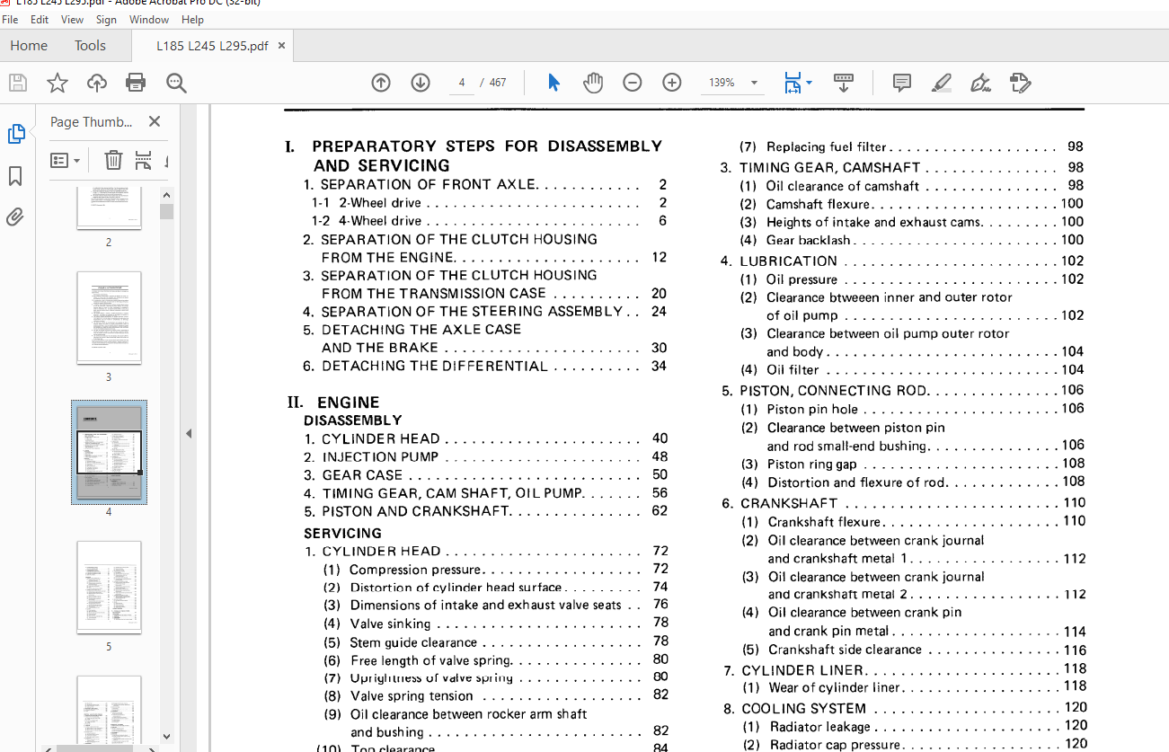
I PREPARATORY STEPS FOR DISASSEMBLY
AND SERVICING
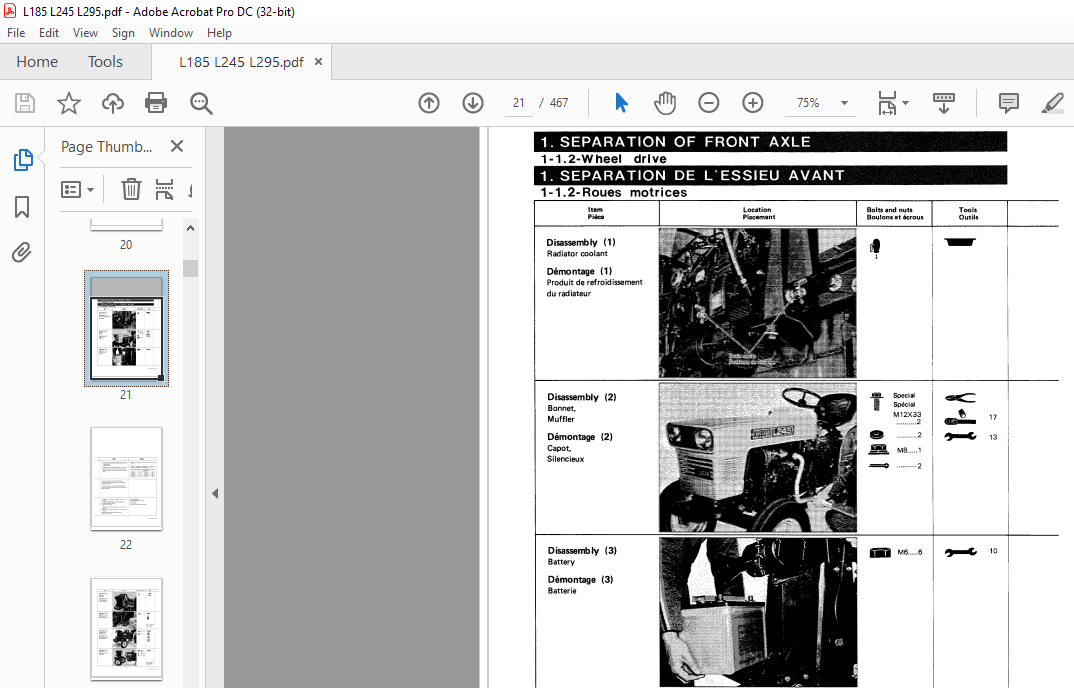
1 SEPARATION OF FRONT AXLE 2
1-1 2-Wheel drive 2
1-2 4-Wheel drive 6
2 SEPARATION OF THE CLUTCH HOUSING
FROM THE ENGINE 12
3 SEPARATION OF THE CLUTCH HOUSING
FROM THE TRANSMISSION CASE 20
4 SEPARATION OF THE STEERING ASSEMBLY 24
5 DETACHING THE AXLE CASE
AND THE BRAKE 30
6 DETACHING THE DIFFERENTIAL 34
II ENGINE
DISASSEMBLY
1 CYLINDER HEAD 40
2 INJECTION PUMP 48
3 GEAR CASE 50
4 TIMING GEAR, CAM SHAFT, OIL PUMP 56
5 PISTON AND CRANKSHAFT 62
SERVICING
1 CYLINDER HEAD 72
(1) Compression pressure 72
(2) Distortion of cylinder head surface 74
(3) Dimensions of intake and exhaust valve seats 76
(4) Valve sinking 78
(5) Stem guide clearance 78
(6) Free length of valve spring 80
(7) Uprightness of valve spring 80
(8) Valve spring tension 82
(9) Oil clearance between rocker arm shaft
and bushing 82
(10) Top clearance 84
( 11) Valve clearance 86
(12) Decompression clearance 86
(13) Air cleaner element 88
2 FUEL SYSTEM 90
(1) Cracking pressure in nozzle 90
(2) Fuel-tightness of nozzle valve seat 92
(3) Shape of fume across nozzle tip 92
(4) Fuel-tightness of fuel injection pump plunger 94
(5) Fuel-tightness of delivery valve
of fuel injection pump 96
(6) Injection timing 96
3
(7) Replacing fuel filter 98
3 TIMING GEAR, CAMSHAFT 98
( 1) Oil clearance of camshaft 98
(2) Camshaft flexure 100
(3) Heights of intake and exhaust cams 100
(4) Gear backlash 100
4 LUBRICATION 102
(1) Oil pressure 102
(2) Clearance btweeen inner and outer rotor
of oil pump 102
(3) Clearance between oil pump outer rotor
and body 104
(4) Oil filter • 104
5 PISTON, CONNECTING ROD 106
( 1) Piston pin hole 1 06
(2) Clearance between piston pin
and rod small-end bushing 106
(3) Piston ring gap 108
(4) Distortion and flexure of rod 108
6 CRANKSHAFT 110
(1) Crankshaft flexure 110
(2) Oil clearance between crank journal
and crankshaft metal 1 112
(3) Oil clearance between crank journal
and crankshaft metal 2 112
(4) Oil clearance between crank pin
and crank pin metal 114
(5) Crankshaft side clearance 116
7 CYLINDER LINER 118
(1) Wear of cylinder liner • 118
8 COOLING SYSTEM • • 120
(1) Radiator leakage • 120
(2) Radiator cap pressure 120
(3) Thermostat operating temperature 122
(4) Fan belt tension 122
TROUBLE SHOOTING 124
III TRACTOR BODY
DISASSEMBLY
1 2-WHEEL DRIVE FRONT AXLE 138
2 4-WHEEL DRIVE FRONT AXLE _ 144
3 CLUTCH 152
4 STEERING SYSTEM 156
KiSC issued 11 , 2015 A
5 TRANSMISSION SYSTEM
(CLUTCH HOUSING SIDE) 160
6 TRANSMISSION SYSTEM
(TRANSMISSION CASE SIDE) 174
7 2 -PINION DIFFERENTIAL GEAR 182
8 4-PINION DIFFERENTIAL GEAR 186
9 REAR A X LE CASE __ 192
SERVICING
1 2-WHEEL DRIVE FRONT AXLE _ 196
( 1) Cl earance between center pin
and center pin bu sh i ng • 196
(2) Su spension force of front ax l e 198
(3) Cl ear ance b etwe en knuckle shaft
and king pin bu shing • 198
(4) Knuckle shaft (upp er, lower ) plays • 200
(5) Front whee l hub deflection 200
(6) Toe- in 202
(7 ) Camber, caster and king pin angles 202
2 4 -WHEEL DRIVE FRONT AXLE 204
(1 ) Rotating torque of spiral bevel pinion shaft 204
(2 ) Diffe rential gear rotating torque 204
(3 ) Backlash betw ee n spi ral bevel pin i on
and bevel gear 206
(4) Bevel gear backla sh in bevel gea r case 206
(5) Bevel gear backla sh in ax le ca se 208
(6) Cl earance between knuckle pin
an d its bu shing _ 208
(7) Clearance between p inion bearing case
and front ax le bracket bushing 210
(8) Clearanc e between center pin
an d differential gear case bushing 210
(9) Clearance betw een drag l i nk end
and knuckl e pin • 212
(10) Front axle suspension force 212
3 CLUTCH 214
(1) Clutch p edal play 214
(2) Safety switch act ion 214
(3) Wear of clutch di sc and main shaft splin e 216
(4) Clutch disc flatness 216
(5) Clutch disc wea r 218
(6) Pre ssur e plate and diaphragm flaws _ 218
(7) Thrust ball b earing 220
(8) Clutch l ever wear and ru st _ 220
4 STEERING SYSTEM 222
4
(1) Vertical jerking of ste ering wheel 222
(2) Steering wheel play 222
(3 ) Jerking of t ie-rod end 224
5 TRANSMISSION SYSTEM _ _ 224
( 1) Gear backlash 224
(2) Cl earanc e betwee n gear and spline 226
(3) Cl earance betwee n sh i ft fork
and shift gear groove 226
(4) Free length of shift fork sprin g 226
(5) Clearance between reverse gear bu shing
and reverse shaft 228
6 2-PINION DIFFERENTIAL GEAR • 230
(1) Clearanc e between diffe re ntial case
and differential si de gear 230
(2) Cle arance between differential pinion shaft
and pin i on gear 232
(3) Backlash between differential pinion
and d iffe re ntial sid e gear 232
(4 ) Diffe rential gear rotating torque 234
(5 ) Backl ash betw ee n spiral bevel pinion
and bev el gear 234
(6) Tooth contact betwee n spi ral bevel pinion
and bevel g ear 236
7 4-PJNION DIFFERENTIAL GEAR _ _ 238
( 1) Back l ash bet w een differ ential pin ion
and differential side gear 238
8 REAR A X LE CASE 240
( 1) Rea r wh ee l d rive gear back l ash 240
9 BRAKE _ 242
( 1) Brak e pedal play • • 242
(2) Brak e cam ac tua t ion 242
(3) Brake cam plate wear • • • 244
(4) Brake cam plate flatn ess • •• 244
(5) Brake d is c wear 244
TROUBLE SHOOTING – – 246
IV HYDRAULIC POWER SYSTEM
SPECIFICATIONS 268
GEAR PUMP
1 CONSTRUCTION AND NAME OF PARTS 270
2 FUNCTION 271
3 DISASSEMBLY 272
4 SERVICING 276
(1) Gap bet we en tooth cres t of gear and body 276
KiSC iss ued 11, 2015 A
(2) Wear of shaft 276
(3) Gap between bushing and shaft 278
(4) Length of bushings “A” and “C” 278
(5) Cleaning oil filter 278
5 BREAKING-IN AND CHECKS 280
• CHECKS BEFORE BREAKING-IN • • 280
5-1 Breaking-in procedures • 280
5-2 Check 280
CONTROL VALVES AND LINKAGE
1 CONSTRUCTION AND NAME OF PARTS _ – 282
1-1 Position control valve and linkage 282
(1) Control valve (L 185, L245, L295) 282
(2) Linkage • • • • • • • • · 282
1-2 Draft control valve and linkage • 283
( 1) Control valve (L295) • • • • · 283
(2) Linkage • • • • 284
1-3 Relief valve • • • • • • • • 284
2 FUNCTION · · · · · · · · · · · · · · 285
2-1 Oil flow in position control valve 285
( 1) When the spool is in the neutral position 285
(2) When the spool is in the up position 285
(3) When the spool is in the down position 286
(4) When the spool is in the floating position 286
2-2 Position control • • • • • • • 287
( 1) Lifting the implement • • • 287
(2) Returning the spool to neutral 287
(3) Lowering the implement – • • 288
(4) Returning the spool to neutral 288
2-3 Draft control • • • • • • · 289
(1) When the draft control is in use
(implement lifted) • 289
(2) When the draft control is in use
(implement lowered) • 291
3 DISASSEMBLY · · · · · · · · · · · · · 292
3-1 Position control valve • • 292
3-2 Draft control valve • • 296
4 SERVICING · · · · · · · 300
4-1 Position control valve 300
(1) Spool faults • • • 300
(2) Checking spool’s slid ing motion – – -300
(3) Unloading valve faults 300
(4) Insufficient contact between check valve
and seat • 302
5
(5) Breakage and deformation of spring 302
(6) Insufficient contact between poppet valve
and seat plug 302
4-2 Draft control valve • 304
( 1) Spool faults • 304
(2) Checking the sliding motion of spool 304
(3) Spring tension • 306
5 ADJUSTMENT 308
5-1 Adjustment and checking
of relief valve set pressure – • 308
• Precautions for relief valve set
pressure adjustment • 308
(1) Checking relief valve set pressure 308
(2) Adjusting the relief valve set pressure 309
5-2 Adjusting the linkage 309
( 1) Position control 309
(2) Draft control _ _ 310
HYDRAULIC CYLINDER
1 CONSTRUCTION AND NAME OF PARTS 312
2 FUNCTION 313
2-1 Oil flow in hydraulic cylinder 313
(1) When the lift arm goes up 313
(2) When the hydraulic lock operates 314
(3) When the hydraulic lock unlocks 315
3 DISASSEMBLY 316
4 SERVICING 324
(1) Wear and fault of hydraulic cylinder 324
(2) Scratch and deformation of piston, O-ring
and backup ring • • • • • · 326
(3) Clearance between hydraulic rod (set pin hole)
and set pin • • • • • · 326
(4) Clearance between hydraulic arm shaft
and hydraulic arm shaft bushing • 328
(5) Scratch on adjust collar • 328
(6) Adjusting spool joint 1 • 328
(7) Operating force of control lever 330
TROUBLE SHOOTING · · 332
V ELECTRICAL SYSTEM
SPECIFICATIONS 346
BATTERY
1 CONSTRUCTION AND NAME OF PARTS · · 348
2 CHEMICAL ACTION 350
KiSC issued 11 , 2015 A
2-1 Chemical action in discharging 350
2-2 Chemical action in charging 351
3_ DEFINITION OF BATTERY PERFORMANCE 352
3-1 Test end voltage 352
3-2 Capacity • • • 353
4 CHECKING AND SERVICING 354
4-1 Routine checks • 354
(1) Terminal and bolt looseness 354
(2) Clean ing the battery surface • • 354
(3) Checking electrolyte 355
4-2 Checking state of charge 356
(1) Checking with a hydrometer 356
(2) Check ing with a battery tester 358
4-3 Recharging 359
( 1) Slow charging 359
(2) Fast charging 361
4-4 Long-term Storage 362
( 1) Checks before and after storage 362
ALTERNATOR AND REGULATOR
1 CONSTRUCTION AND NAME OF PARTS 364
1-1 Alternator 364
1-2 Regulator • 366
2 CHARGING CIRCUIT 367
3 CHARGING OPERATION 368
3-1 Turning the main switch on 368
3-2 Low-speed runn ing 369
3-3 Medium-speed running 370
3-4 High-speed running 371
4 CHECKS 372
(1) Rotor coil, slip ring, brush 372
(2) Coupler voltage 372
(3) Output current 374
(4) No-load testing of alternator 374
(5) Diodes • • 376
(6) No-load regulating voltage • 376
(7) Cut-in voltage 378
(8) Regulator check 380
5 DISASSEMBLY 386
6 SERVICING 390
(1) Slip ring 390
(2) Rotor coil resistance 390
(3) Insulat ion between rotor coi l and core 390
(4) Bru sh wear 392
(5) Stator coil breakage 392
6
(6) Stator coil short-circuit • •• • 392
(7) Check ing posit ive diodes 394
(8) Checking negative diodes • 394
STARTER AND GLOWPLUG
■ MAGNET SWITCH TYPE STARTER
1 CONSTRUCTION AND NAME OF PARTS 398
2 STARTING CIRCUIT 402
3 ELECTRICAL WIRING AND OPERATION 403
3-1 Switching the starter on 403
3-2 Contact plate is closed 404
3-3 Starter switch is released ‘ 405
4 CHECKS 406
(1) No-load testing 406
(2) Motor te st 408
(3) Safety switch 408
5 DISASSEMBLY – 410
6 SERVICING 414
(1) Pull -in coil (Attraction test) 414
(21 Holding coil (Retention test) 414
(3) Plunger return 416
(4) Piniongap 416
(5) Gap between shaft and bush 418
(6) Armature flexure 418
(7 I Armature coil short-circu it 420
(8) Armature coil breakage 420
(9) Armature coil groundir g 420
(10) Uneven wear of commutator 422
(11) Staining or burning of commutator 422
(12) Mica (undercut) 424
(13) Field coil breakage 424
(14 ) Insulation between field coil and yoke 424
(15) Wear of brush 426
(16) Brush spring tension 426
( 17) Brush holder 426
■ REDUCTION STARTER 428
1 CONSTRUCTION AND NAME OF PARTS 428
2 ELECTRICAL WIRING AND OPERATION 429
3 DISASSEMBLY · 430
■ GLOW PLUG 434
1 CONSTRUCTION AND NAME OF PARTS 434
2 CHECKS 434
(11 Breakage and short-circuit of glow plug 434
TROUBLE SHOOTING 436
ELECTRICAL WIRING L 185 • L245 448
ELECTRICAL WIRING L295 450
More products