$36
Kubota Tractor M7132 M7152 M7172 DeTier Workshop Manual – PDF DOWNLOAD
Kubota Tractor M7132 M7152 M7172 DeTier Workshop Manual – PDF DOWNLOAD
FILE DETAILS:
Kubota Tractor M7132 M7152 M7172 DeTier Workshop Manual – PDF DOWNLOAD
Language : English
Pages : 1716
Downloadable : Yes
File Type : PDF
Size: 320 MB
IMAGES PREVIEW OF THE MANUAL:
DESCRIPTION:
Kubota Tractor M7132 M7152 M7172 DeTier Workshop Manual – PDF DOWNLOAD
TO THE READER:
This workshop manual provides safety information for service activity, general information such as specifications and
dimensions of the machine, mechanisms and structure descriptions of the machine, and service procedures.
Safety
This section contains safety service descriptions and safety label information.
General
This section contains general instructions, tightening torques, general machine information and special tools.
Maintenance
This section contains information for the recommended oil and general maintenance procedures.
Each section basically consists of mechanism and servicing.
Mechanism
Mechanism part contains information and explanations for the structure, functions, and specifications of the machine
or component parts. This part should be comprehended before proceeding with troubleshooting, disassembling,
assembling, and servicing works.
Servicing
Servicing part contains information and procedures for maintenance, troubleshooting and repair works. The reader
should follow these instructions in order to satisfy any servicing work safely, correctly and quickly.
In this WSM, service specifications and service limits are defined as followings.
Service specifications:
Specification which corresponds to new machine’s ex-factory. It is based on quality standard, drawings, or actual
measurements conducted by Kubota. This value is used to determine whether there is a problem with the machine in
the event of a troubleshooting. However, it is necessary to consider degradation due to wear, based on the operating
time of the machine, application or maintenance condition.
Service limits:
Service limit is a value corresponding to the recommended performance limit by taking long term-use wear into
account. When the service limit is reached , the machine is required to have proper repair, overhaul or replacement in
order to keep safe and adequate performance.
All of the illustrations, photographs, specifications, and other information in this manual were created based on the
latest model at the time of publication.
The parts names used in this manual are unified into names representing the functions of the parts. Therefore, it does
not necessarily correspond to the names used in other materials (parts list, operators manual etc.) and the name on
the label/ identification plates on the product.
Kubota reserves the right to change all information at any time without notice.
Kubota Tractor M7132, M7152, and M7172 are powerful and versatile tractors designed and manufactured by Kubota Corporation, a Japanese company that produces a wide range of agricultural and construction equipment. These tractors are designed for use in a variety of farming applications, including planting, harvesting, and transportation.
- Engine and Transmission: The M7132, M7152, and M7172 are powered by a 4-cylinder turbocharged diesel engine that delivers high horsepower and torque for efficient operation. The engines are paired with a 24-speed powershift transmission that provides smooth and efficient shifting for maximum productivity.
- Hydraulics and PTO: The tractors feature a hydraulic system that provides high flow rates for efficient operation of hydraulic implements, such as loaders and backhoes. The tractors also have a standard rear PTO and optional front PTO that can power a variety of implements, such as mowers and snow blowers.
- Cab and Comfort: The M7132, M7152, and M7172 tractors have a spacious cab that is designed for operator comfort and convenience. The cabs are equipped with air conditioning and heating systems for year-round comfort, as well as a premium sound system for entertainment during long hours in the field. The tractors also have a high-visibility roof panel that provides excellent visibility for loader operations.
- Technology: The M7132, M7152, and M7172 tractors are equipped with advanced technology features that help to increase productivity and efficiency. The tractors have an Intelli-Shift transmission that automatically shifts gears for optimal performance and fuel efficiency. They also have an Auto-Guide GPS system that provides accurate and efficient guidance for planting and harvesting operations.
- Safety and Maintenance: The tractors are designed with safety and maintenance in mind. They have a range of safety features, including a roll-over protection system (ROPS), a seat belt, and an engine shut-off switch. The tractors also have easy access points for daily maintenance tasks, such as engine oil and filter changes.
Overall, the Kubota Tractor M7132, M7152, and M7172 are powerful and versatile machines that are ideal for a range of farming applications. They offer advanced technology features, operator comfort, and safety features, making them a popular choice for farmers and agricultural contractors.
TABLE OF CONTENTS:
Kubota Tractor M7132 M7152 M7172 DeTier Workshop Manual – PDF DOWNLOAD
1 SAFETY
SAFETY FIRST 1-1
1 Working precautions 1-1
2 Preparing for emergencies 1-1
3 Working cautions 1-2
4 Starting machine safely 1-2
5 Preventing fires 1-3
6 Preventing acid burns 1-3
7 Avoiding high pressure fluid 1-3
8 Avoiding hot exhaust 1-4
9 Cleaning exhaust filter 1-4
SAFETY LABELS 1-5
2 GENERAL
GENERAL 2-1
1 General working precautions 2-1
2 Tightening bolts and nuts 2-1
3 Applying thread-locking fluid 2-1
4 Installing circlips 2-2
5 Installing spring pins 2-2
6 Handling split pin 2-2
7 Handling chain joint and split pin 2-2
8 Handling liquid gasket 2-3
9 Replacing O-rings 2-3
10 Replacing oil seals 2-3
11 Replacing floating seals 2-4
12 Connecting hydraulic hoses 2-4
13 Wrapping thread seal tape 2-4
14 Installing elbows with male seat 2-4
15 Connecting and disconnecting quick hose couplings 2-5
16 Handling the battery 2-5
17 Handling wire harness 2-5
18 Handling fuses 2-7
19 Handling connectors 2-7
20 Wiring color 2-8
21 Washing the machine with a high pressure washer 2-8
22 Dispose fluids correctly 2-9
23 Using DEF/AdBlue® 2-9
TIGHTENING TORQUES 2-11
1 General use screws, bolts and nuts 2-11
2 Stud bolts 2-12
3 Hydraulic fittings 2-13
3 1 Hydraulic hose tightening torque 2-13
3 2 Hydraulic pipe cap nuts 2-1 3
3 3 Adaptors, elbows and nuts 2-13
3 4 Hydraulic pipes tightening torque 2-14
3 5 Hydraulic joint nut tightening torque 2-15
3 6 Hydraulic pipe joint tightening torque (PT thread) 2-15
4 Pneumatic fittings 2-15
4 1 Tightening torque for pneumatic fittings 2-15
TRACTOR IDENTIFICATION 2-17
1 Model name and serial number 2-17
SPECIFICATION TABLE 2-19
TRAVELING SPEEDS 2-21
M7132,M7152,M7172,DeTier iii
KiSC issued 05, 2021 A
DIMENSIONS 2-23
SPECIAL TOOLS 2-25
1 General 2-25
1 1 Diagnosis tool kit (K-OBD) 2-25
1 2 CAN BUS interface 2-25
1 3 Tractor CAN BUS connector 2-25
2 Engine 2-26
2 1 Diesel engine compression tester 2-26
2 2 Oil pressure tester 2-26
2 3 Diagnosis tool kit 2-26
2 4 Valve seat cutter 2-26
2 5 Connecting rod alignment tool 2-27
2 6 Plastigauge 2-27
2 7 Radiator tester 2-27
2 8 Compression tester adapter (Glow plug adapter) 2-28
2 9 Valve guide replacing tool 2-29
2 10 Idle gear bushing replacing tool 2-29
2 11 Small end bushing replacing tool 2-30
2 12 Balancer shaft bearing replacing tool 2-31
2 13 Balancer shaft bearing replacing tool B 2-33
2 14 Balancer shaft bearing replacing tool C 2-35
2 15 Balancer shaft bearing replacing tool D 2-37
2 16 Oil seal installing tool A 2-39
2 17 Oil seal installing tool B 2-40
2 18 DEF header unit replacing tool (if equipped) 2-41
3 Front axle 2-42
3 1 Heavy duty front axle 2-42
4 Transmission 2-61
4 1 Powershift transmission 2-61
4 1 1 Eyebolt (M12) 2-61
4 1 2 Load ring 2-61
4 1 3 Eyebolt 2-61
4 1 4 Eyebolt 2-61
4 1 5 Basic tool 2-61
4 1 6 Gripping device 2-62
4 1 7 Plug insert 2-62
4 1 8 Basic tool 2-62
4 1 9 Driver tool 2-62
4 1 10 Measuring support 2-62
4 1 11 Straightedge 2-63
4 1 12 Handle 2-63
4 1 13 Driver tool 2-63
4 1 14 Driver tool 2-63
4 1 15 Striker 2-63
4 1 16 Grab sleeve 2-64
4 1 17 Basic tool 2-64
4 1 18 Press bush 2-64
4 1 19 Grab sleeve 2-64
4 1 20 Grab sleeve 2-64
4 1 21 Grab sleeve 2-65
4 1 22 Basic tool 2-65
4 1 23 Puller 2-65
4 1 24 Basic tool 2-65
4 1 25 Grab sleeve 2-65
4 1 26 Sleeve 2-66
4 1 27 Locating pin 2-66
4 1 28 Locating pin (M 10) 2-66
4 1 29 Fixture 2-66
iv M71 32,M7152,M7172,DeTier
KiSC issued 05, 2021 A
4 1 30 Extractor 2-66
4 1 31 Plug insert 2-67
4 1 32 Clamping device 2-67
4 1 33 Assembly lever 2-67
4 1 34 Slotted nut wrench 2-67
4 1 35 Clamping bar 2-67
4 1 36 Grab sleeve 2-68
4 1 37 Grab sleeve 2-68
4 1 38 Adjusting screws (M8) 2-68
4 1 39 Adjusting screws (M14) 2-68
4 1 40 Measuring lever 2-68
4 1 41 Driver tool 2-69
4 1 42 Driver tool 2-69
4 1 43 Driver tool 2-69
4 1 44 Clamping device 2-69
4 1 45 Transmission stand with tilting device 2-69
4 1 46 Striker 2-70
4 1 47 Eyebolt 2-70
4 1 48 Assembly fixture 2-70
4 1 49 Centering device 2-70
4 1 50 Handle 2-70
4 1 51 Offset screwdriver 2-71
4 1 52 Plug insert 2-71
4 1 53 Rapid grip 2-71
4 2 CVT 2-71
4 2 1 Adjusting screws 2-71
4 2 2 Striker 2-71
4 2 3 Load carrying fixture 2-72
4 2 4 Assembly aid 2-72
4 2 5 Locating pin 2-72
4 2 6 Locating pin 2-72
5 Rear axle 2-72
5 1 Slotted nut wrench 2-72
5 2 Grab sleeve 2-73
5 3 Socket wrench 2-73
5 4 Slotted nut wrench 2-73
5 5 Grab sleeve 2-73
5 6 Basic tool 2-73
5 7 Assembly fixture 2-7 4
5 8 Pressure pin 2-74
5 9 Locating pins (M12) 2-74
5 10 Straightedge 2-7 4
5 11 Spring scale 2-7 4
5 12 Driver tool 2-75
5 13 Driver tool 2-75
5 14 Driver tool 2-75
5 15 Handle 2-75
5 16 Assembly fixture 2-75
5 17 Insert (M22 x 1 5) 2-76
5 18 Pressure ring 2-76
5 19 Press-fit mandrel 2-76
5 20 Locating pins (M14) 2-76
6 Hydraulic 2-76
6 1 Complete suitcase with component 2-76
6 2 Empty case 2-77
6 3 Adaptor of PST main clutch 2-77
6 4 Adaptor of PST system 2-77
6 5 Adaptor of PST clutch/4WD clutch 2-77
M7132,M7152,M7172,DeTier V
KiSC issued 05, 2021 A
6 6 Adaptor of CVT 2-78
6 7 T-joint for differential lock 2-78
6 8 Adaptor of PTO 2-78
6 9 Adaptor of auxiliary valve 2-78
6 10 Kit for pump flow 2-79
6 11 Kit for pump flow 2-79
6 12 T-joint of steering valve· ···· ··· ······ ··· ············ ············ ·········· ········ ······ ···· ········ ···· ··· ········ ·· ········· ····· ····· 2-79
6 13 Adaptor of front PTO··· ······· ········ ······ ········· ········ ···· ······ ···· ········ ······ ···· ········ ····· ···· ···· ······· ·· ·· ······ ··· ··· 2-79
6 14 Pressure gauge 2-79
6 15 Hydraulic cable 2-80
6 16 Cylinder safety valve setting pressure adaptor 2-80
6 17 Hydraulic cylinder block tool 2-82
6 18 Adapter for flow meter 2-84
7 Cabin 2-84
7 1 General 2-84
7 1 1 Toe-in gauge 2-84
7 1 2 Cabin lifting tool 2-85
7 2 Air conditioner 2-91
7 2 1 Air conditioner service tool 2-92
7 2 2 Electric gas leak tester 2-93
7 2 3 Vacuum pump 2-93
7 2 4 Adaptor (for R134a) 2-93
7 2 5 Stopper magnetic clutch (for A/C compressor) 2-94
7 2 6 Stopper bolt (for A/C compressor) 2-95
8 Front suspension 2-95
8 1 Accumulator gas charge kit 2-95
8 1 1 Pressure reducer 2-96
8 1 2 Charging hose 2-97
8 1 3 Adaptor 2-97
3 MAINTENANCE
LUBRICANTS, FUEL AND COOLANT 3-1
1 DEF (AdBlue) (If equipped) 3-3
1 1 Handling DEF (AdBlue) 3-3
1 2 Quality of DEF (AdBlue) 3-3
1 3 Adding DEF (AdBlue) 3-3
1 4 Draining DEF (AdBlue) 3-4
1 5 Storing purchased DEF (Ad Blue) 3-4
1 6 Storing DEF (Ad Blue) in the DEF tank 3-5
1 7 Disposing of DEF (AdBlue) 3-5
1 8 Handling precautions after stopping the engine 3-5
1 9 Precautions when using in cold regions 3-5
2 Biodiesel fuel (BDF) 80-85 3-6
SERVICE INTERVALS 3-9
MAINTENANCE ITEMS CHART 3-1 3
CHECK AND MAINTENANCE 3-15
1 Daily check 3-15
1 1 Walk around inspection 3-15
1 2 Checking and refueling 3-15
1 3 Checking DEF/AdBlue® level and adding fluid (if equipped) 3-15
1 4 Checking pneumatic brake pressure (if equipped) 3-16
1 5 Checking water separator 3-16
1 6 Checking engine oil level 3-17
1 7 Checking transmission fluid level 3-17
1 8 Checking coolant level 3-18
1 9 Cleaning grill, radiator, and cooler 3-1 8
1 10 Checking DPF muffler I SCR device (if equipped) 3-19
1 11 Checking brake pedal 3-20
vi M71 32,M7152,M7172 ,DeTier
KiSC issued 05, 2021 A
1 12 Checking parking brake 3-20
1 13 Checking gauges, meter and Easy Checker 3-20
1 14 Checking headlight, turn signal light, hazard light, and so on 3-20
1 15 Checking seat belt 3-20
1 16 Checking movable parts 3-20
2 Initial 5, 10, 25, and 50 hours 3-20
2 1 Tightening bar axle torque 3-20
3 Initial 50 hours 3-21
3 1 Changing engine oil 3-21
3 2 Replacing engine oil filter 3-21
3 3 Checking fan belt 3-21
3 4 Replacing transmission oil filter 3-21
4 Every 50 hours 3-21
4 1 Checking neutral circuit 3-21
4 1 1 Preparation before testing 3-21
4 1 2 Testing engine start system 3-21
4 1 3 Testing transmission (neutral) control 3-21
4 1 4 Testing hydraulic up/down (lock) control 3-22
4 1 5 Testing remote hydraulic control (Premium, Premium KVT models) 3-22
4 1 6 Testing external rear PTO switch control 3-23
4 1 7 Checking operator presence control (OPC) system 3-24
4 1 8 Testing operator presence control (OPC) system (Standard, Premium models) 3-25
4 1 9 Testing operator presence control (OPC) system (Premium KVT model) 3-25
4 1 10 Testing operator presence control (OPC) system 3-25
4 2 Checking wheel bolt torque 3-25
4 3 Checking tie-rod dust cover 3-26
4 4 Checking air brake for trailer (if equipped) 3-26
5 Every 100 hours 3-27
5 1 Cleaning air cleaner primary element 3-27
5 1 1 Cleaning pre-cleaner tubes 3-27
5 1 2 Replacing secondary element 3-27
5 2 Lubricating grease fittings 3-28
5 3 Adjusting brake pedal 3-29
5 3 1 Checking brake pedal free travel 3-29
5 3 2 Checking brake pedal stroke 3-30
5 3 3 Checking equalizer working level (anti-imbalance device) 3-30
5 4 Adjusting parking brake lever 3-30
5 5 Checking battery condition 3-30
5 5 1 Charging the battery 3-31
5 5 2 Directions for battery storage 3-31
5 5 3 How to detach the battery 3-32
5 6 Checking front PTO oil (if equipped) 3-32
6 Every 200 hours 3-32
6 1 Draining fuel tank water 3-32
6 2 Adjusting toe-in 3-33
6 2 1 Adjusting toe-in procedure 3-33
6 3 Cleaning inner air filter 3-33
6 4 Cleaning fresh air filter 3-34
6 4 1 Cleaning the filter 3-34
7 Every 400 hours 3-34
7 1 Checking fan belt tension 3-34
7 1 1 Replacing the belt 3-35
7 2 Cleaning water separator 3-36
7 3 Cleaning fuel solenoid pump element 3-36
8 Initial 500 hours 3-37
8 1 Changing transmission fluid 3-37
8 2 Changing rear axle case oil 3-37
8 3 Replacing transmission oil filter 3-37
M7132,M7152,M71 72,DeTier vii
KiSC issued 05, 2021 A
9 Every 500 hours 3-37
9 1 Changing engine oil 3-37
9 2 Replacing engine oil filter 3-38
9 3 Cleaning pre-fuel filter 3-38
9 4 Replacing fuel filter 3-39
9 5 Replacing hydraulic oil filter (suction) 3-39
9 6 Replacing hydraulic oil filter (return) 3-41
9 7 Replacing power steering oil filter 3-41
9 8 Checking radiator hose and clamp 3-42
9 8 1 Overheating countermeasures 3-43
9 9 Checking fuel line 3-43
9 10 Checking intake air line 3-44
9 11 Checking brake hose 3-44
9 12 Checking differential lock hose 3-44
9 13 Checking lift cylinder hose 3-44
9 14 Checking power steering line 3-45
9 15 Checking oil cooler line 3-45
9 16 Checking front suspension hose 3-45
9 17 Checking air conditioner pipe and hose 3-46
9 18 Checking air conditioner drive belt 3-46
9 18 1 Replacing the belt 3-46
9 19 Changing front PTO oil (if equipped) 3-46
10 Every 1000 hours 3-4 7
10 1 Changing transmission fluid 3-4 7
10 2 Replacing transmission oil filter 3-48
10 3 Changing rear axle case oil 3-49
10 4 Changing front differential case oil 3-49
10 5 Changing front axle gear case oil 3-49
10 6 Checking valve clearance 3-50
11 Every 1000 hours or 1 Year 3-50
11 1 Replacing air cleaner primary element and secondary element 3-51
11 2 Checking exhaust manifold 3-51
12 Every 1500 hours 3-51
12 1 Cleaning fuel injector nozzle tip 3-51
12 2 Checking DEF/AdBlue® injector tip (if equipped) 3-51
12 3 Checking DEF (AdBlue) line (if equipped) 3-52
12 4 Replacing oil separator element 3-52
12 5 Checking positive crankcase ventilation (PCV) valve 3-53
12 6 Checking and cleaning EGR cooler (if equipped) 3-53
12 7 Checking accumulator gas pressure (Front suspension type) 3-53
13 Every 2000 hours or 2 years 3-54
13 1 Flushing cooling system and changing coolant 3-54
13 2 Antifreeze 3-55
14 Every 3000 hours 3-56
14 1 Checking turbocharger 3-56
14 1 1 Checking turbine side of turbocharger 3-56
14 1 2 Checking compressor side of turbocharger 3-56
14 2 Checking supply pump 3-57
14 3 Checking and cleaning EGR system (if equipped) 3-57
14 4 Cleaning DPF muffler (if equipped) 3-57
14 5 Checking DEF/AdBlue® injector (if equipped) 3-57
14 6 Replacing DEF pump filter (if equipped) 3-58
15 Every 8000 hours 3-59
15 1 Replacing DEF/AdBlue® tank filter (if equipped) 3-59
16 Every 3 months 3-59
16 1 Checking the quality of DEF (Ad Blue) (if equipped) 3-59
17 Every 1 year 3-59
17 1 Checking DPF differential pressure sensor pipe (if equipped) 3-59
viii M7132,M7152,M7172,DeTier
KiSC issued 05, 2021 A
17 2 Checking EGR pipe (if equipped) 3-59
17 3 Checking CAB isolation cushion 3-60
17 4 Checking oil separator hose 3-60
18 Every 2 years 3-60
18 1 Replacing DPF differential pressure sensor hose (if equipped) 3-60
18 2 Replacing boost sensor hose 3-61
19 Every 3 years 3-61
19 1 Removing parking brake cable 3-61
20 Every 4 years 3-61
20 1 Replacing radiator hose (water pipes) 3-61
20 2 Replacing oil cooler line 3-61
20 3 Replacing intake air line 3-61
20 4 Replacing oil separator hose 3-62
20 5 Replacing oil cooler line 3-62
20 6 Replacing power steering hose 3-62
20 7 Replacing lift cylinder hose 3-62
20 8 Replacing differential lock hose 3-62
20 9 Replacing front suspension hose (Front suspension type) 3-63
20 10 Replacing brake hose 3-64
20 11 Replacing air conditioner hose 3-64
21 Service as required 3-64
21 1 Bleeding fuel system 3-64
21 2 Bleeding brake system 3-64
21 3 Replacing fuses 3-65
21 4 Replacing light bulb 3-68
21 5 Replacing headlight bulb 3-68
21 6 Lubricating points for door and window 3-68
21 7 Adding washer liquid 3-68
21 8 Checking amount of refrigerant (gas) 3-68
21 9 Washing the tractor 3-69
4 ENGINE
MECHANISM 4-1
1 Features of the engine 4-1
2 Engine body 4-1
2 1 Structure of cylinder block 4-1
2 2 Function of center direct injection system (E-CDIS) ·· ······· ·· ········ ·· ·· ······ ·············· ············ ·· ·· ······ ··· ·· ··· 4-2
2 3 Function of piston 4-2
2 4 Function of balancer 4-2
3 Lubricating system 4-3
3 1 Function of oil cooler 4-3
3 2 Function of oil separator 4-3
4 Cooling system 4-4
4 1 Thermostat 4-4
4 1 1 Structure of thermostat 4-4
4 1 2 Operation of thermostat 4-5
4 1 3 Flow characteristic of thermostat 4-6
4 2 Function of bottom bypass system 4-6
4 3 Structure diagram of the cooling system 4-7
4 4 Function of viscous coupling fan 4-10
5 Common rail system (CRS) 4-11
5 1 Structure of the common rail system 4-11
5 2 Outline of fuel system 4-13
5 3 Structure of supply pump ······ ··············· ····· ···· ···· ···· ·· ···· ··· ········ ···· ····· ····· ·· ··· ······· ·· ······· ······ ·········· ······4-14
5 3 1 Function of feed pump 4-14
5 3 2 Function of regulating valve 4-14
5 3 3 Function of suction control valve (SCV) 4-15
5 3 4 Function of pump unit 4-16
M7132 M7152,M7172,DeTier ix
KiSC issued 05, 2021 A
5 3 5 Function of delivery valve 4-16
5 3 6 Function of fuel temperature sensor 4-16
5 4 Function of rail 4-16
5 5 Function of injector 4-17
5 5 1 Operation of injector 4-19
5 5 2 Electrical circuit of injector drive 4-21
5 5 3 Function of injector QR/ID codes 4-21
5 5 4 Handling of injectors with QR codes (Reference) 4-21
5 6 Engine control system 4-22
5 6 1 Diagram of engine control system 4-22
5 6 2 Function of the engine electronic control unit (ECU) 4-25
5 6 3 Sensors 4-25
6 Exhaust gas recirculation (EGR) system (if equipped) 4-30
6 1 General structure of EGR system 4-30
6 1 1 Structure of high pressure EGR system 4-32
6 1 2 Structure of low pressure EGR system 4-32
6 2 Function of EGR valve 4-33
6 2 1 Function of EGR valve lift sensor 4-34
6 3 Function of reed valve 4-34
7 After treatment system (if equipped) 4-35
7 1 Schematic diagram of after treatment devices 4-35
7 2 Components 4-36
7 2 1 Function of diesel oxidation catalyst (DOC) 4-36
7 2 2 Function of diesel particulate filter (DPF) 4-36
7 2 3 Function of intake throttle valve 4-36
7 2 4 Function of air flow sensor 4-36
7 2 5 Function of temperature sensor 4-37
7 2 6 Function of differential pressure sensor 4-37
7 2 7 Function of selective catalytic reduction (SCR) 4-37
7 2 8 Function of diesel exhaust fluid (DEF) pump 4-38
7 2 9 Function of DEF injector 4-38
7 2 10 Function of the DEF tank 4-39
7 2 11 Function of coolant valve 4-39
7 2 12 Function of after treatment control unit (ACU) 4-40
7 3 SCR system 4-41
7 3 1 Outline of the SCR system 4-41
7 3 2 Flow of coolant and DEF in SCR system 4-42
7 3 3 Process of thaw control 4-42
7 3 4 Warning indication and countermeasures 4-42
7 4 DPF regeneration system 4-46
7 4 1 Outline of regeneration mode 4-46
7 4 2 Function of indicators and switch lamps 4-4 7
SERVICING 4-49
1 Troubleshooting for engine 4-49
2 Service specifications for engine 4-53
3 Tightening torques for engine 4-57
4 Checking, disassembling, and servicing 4-59
4 1 Checking and adjusting 4-59
4 1 1 Engine body 4-59
4 1 2 Lubricating system 4-60
4 1 3 Cooling system 4-60
4 1 4 Turbocharger 4-63
4 2 Preparation 4-63
4 2 1 Separating cabin from tractor 4-63
4 2 2 Removing SCR (if equipped) 4-79
4 2 3 Removing DPF muffler (if equipped) 4-80
4 2 4 Removing exhaust pipes 4-82
4 2 5 Oil cooler pipe, wire harness, fuel hose 4-83
X M7132,M7152,M7172,DeTier
KiSC issued 05, 2021 A
4 2 6 Main frame 4-83
4 3 Disassembling and assembling 4-85
4 3 1 DPF muffler (if equipped) 4-85
4 3 2 External components 4-87
4 3 3 Exhaust gas recirculation (EGR) (Low pressure side) (if equipped) 4-88
4 3 4 Turbocharger 4-88
4 3 5 Exhaust gas recirculation (EGR) (High pressure side) (if equipped) 4-89
4 3 6 Common rail system (CRS) 4-90
4 3 7 Cylinder head and valve 4-92
4 3 8 Thermostat 4-99
4 3 9 Water pump and oil cooler 4-99
4 3 10 Front cover 4-100
4 3 11 Flywheel and flywheel housing 4-101
4 3 12 Piston and connecting rod 4-106
4 3 13 Crankshaft and crankcase 4-110
4 3 14 Timing gears 4-111
4 4 Servicing 4-112
4 4 1 Cylinder head and valve 4-112
4 4 2 Timing gears 4-120
4 4 3 Piston and connecting rod 4-125
4 4 4 Crankshaft 4-128
4 4 5 Cylinder 4-131
4 4 6 Oil pump 4-132
4 5 Replacing 4-133
4 5 1 Replacing supply pump 4-133
4 5 2 Replacing injector 4-135
4 5 3 Replacing engine ECU 4-137
4 5 4 Replacing the DPF (if equipped) 4-140
4 5 5 Replacing the SCR (if equipped) 4-147
4 5 6 Replacing the ACU (if equipped) 4-147
4 5 7 Replacing the DEF injector (if equipped) 4-151
4 5 8 Replacing the header unit of the DEF tank (if equipped) 4-153
5 TRANSMISSION
MECHANISM 5-1
1 Power shift 5-1
1 1 Structure 5-1
1 1 1 Structure of power shift traveling system 5-1
1 1 2 Structure of PTO (Power shift) 5-3
1 2 Operation of power train 5-4
1 2 1 Operation of power shift section 5-4
1 2 2 Operation of range and creep shift section 5-6
1 2 3 Operation of PTO shift section 5-6
1 3 Hydraulic control of power shift 5-7
1 3 1 Hydraulic circuit 5-7
1 3 2 Component parts of power shift hydraulic control system 5-10
1 4 Electric control system 5-16
1 4 1 Electrical control system of power shift 5-16
1 4 2 Power shift transmission – switch and sensor location 5-17
1 4 3 Component parts 5-18
2 CVT 5-25
2 1 Structure 5-25
2 1 1 Traveling system of CVT 5-25
2 1 2 Structure of PTO (CVT) 5-27
2 2 Operation of power train 5-28
2 2 1 Operation principle of CVT 5-28
2 2 2 Driving chart and gear shift pattern of CVT 5-29
2 3 Hydraulic system 5-32
M71 32,M7152,M71 72,DeTier xi
KiSC issued 05, 2021 A
2 3 1 Hydraulic circuit 5-32
2 3 2 Component parts of CVT hydraulic control system 5-33
2 4 Electric control system 5-35
2 4 1 Electric control system of CVT 5-35
2 4 2 CVT – switch and sensor location 5-36
2 4 3 Component parts 5-36
3 FrontPTO 5-37
3 1 Structure of front PTO 5-37
3 2 Hydraulic circuit of front PTO 5-38
3 3 System component of front PTO 5-39
3 3 1 Front PTO soft start control 5-40
SERVICING 5-41
1 Power shift 5-41
1 1 Troubleshooting for transmission (Power shift) 5-41
1 2 Service specifications for transmission (Power shift) 5-4 7
1 3 Tightening torques for transmission (Power shift) 5-48
1 4 Checking and adjusting 5-50
1 4 1 System pressure 5-50
1 4 2 Hydraulic control for power shift 5-50
1 4 3 Main clutch 5-51
1 4 4 PTO clutch 5-51
1 4 5 Differential lock 5-52
1 4 6 4 wheel drive 5-52
1 4 7 Lubrication 5-53
1 5 Preparation 5-53
1 5 1 Separating power shift transmission from tractor 5-53
1 5 2 Separating rear axle case from transmission case 5-69
1 6 Disassembling 5-72
1 6 1 Removing range shift valve (IRS valve) (without removing cabin) 5-72
1 6 2 Removing powershift valve block (without removing cabin) 5-73
1 6 3 Removing damper disc 5-76
1 6 4 Removing input shaft 5-76
1 6 5 Removing clutch housing from transmission housing 5-77
1 6 6 Disassembling clutch housing 5-78
1 6 7 Disassembling transmission housing 5-90
1 7 Assembling 5-116
1 7 1 Assembling clutch housing 5-116
1 7 2 Assembling transmission housing 5-139
1 7 3 Mounting clutch housing to transmission housing 5-193
1 7 4 Installing inputshaft 5-196
1 7 5 Installing oil supply 5-197
1 7 6 Adjusting crawler gear shift system 5-198
1 7 7 Mounting main transmission to rear axle 5-199
1 7 8 Closing components 5-202
2 CVT 5-204
2 1 Troubleshooting for transmission (CVT} 5-204
2 2 Service specifications for transmission (CVT) 5-207
2 3 Tightening torques for transmission (CVT) 5-208
2 4 Checking and adjusting 5-210
2 4 1 Checking system pressure 5-210
2 4 2 Checking lubrication pressure 5-210
2 4 3 Checking 4 wheel drive operating pressure 5-210
2 4 4 Checking PTO clutch operating pressure 5-210
2 4 5 Checking differential lock operating pressure 5-211
2 4 6 CF, CR, C1, C2, C3, C4 and BG clutch 5-211
2 4 7 Diagnostic protocol of KVT model 5-212
2 5 Preparation 5-216
2 5 1 Separating CVT from tractor 5-216
xii M7132,M7152,M7172,DeTier
KiSC issued 05, 2021 A
2 6 Disassembling 5-239
2 6 1 Removing speed sensor, pressure sensor, solenoid valve and inductive sensor 5-239
2 6 2 Removing clutch control 5-240
2 6 3 Removing oil supply 5-242
2 6 4 Removing system control 5-243
2 6 5 Removing hydraulic unit 5-245
2 7 Assembling 5-249
2 7 1 Assembling hydraulic unit 5-249
2 7 2 Assembling system control 5-254
2 7 3 Assembling oil supply 5-257
2 7 4 Assembling clutch control 5-259
2 7 5 Assembling inductive sensor, solenoid valve, pressure sensor, speed sensor and speed
transmitter 5-264
3 Rear component 5-266
3 1 Disassembling 5-266
3 1 1 Disassembling differential 5-266
3 1 2 Disassembling PTO 5-268
3 1 3 Oil supply and power lift 5-273
3 2 Assembling 5-277
3 2 1 Power lift and oil supply 5-277
3 2 2 PTO 5-286
3 2 3 Differential 5-296
4 Front PTO 5-302
4 1 Troubleshooting for transmission (Front PTO) 5-302
4 2 Service specifications for transmission (Front PTO) 5-303
4 3 Checking and adjusting 5-304
4 3 1 Clutch pressure 5-304
4 3 2 Pump pressure 5-304
4 4 Preparation 5-304
4 4 1 Separating front PTO from tractor 5-304
4 5 Disassembling 5-307
4 5 1 Oil pump 5-307
4 5 2 PTO unit 5-308
4 5 3 Clutch 5-309
4 5 4 Piston 5-311
4 6 Assembling 5-312
4 6 1 Clutch 5-312
4 6 2 PTO unit 5-313
4 6 3 Oil pump 5-314
6 REAR AXLE
MECHANISM 6-1
1 Structure 6-1
1 1 Structure of rear axle 6-1
1 2 Structure of bar axle 6-2
1 2 1 Structure of classical type bar axle 6-2
1 2 2 Structure of plug on type bar axle 6-2
SERVICING 6-3
1 Troubleshooting for rear axle 6-3
2 Tightening torques for rear axle 6-4
3 Checking, disassembling, and servicing 6-5
3 1 Preparation 6-5
3 1 1 Separating rear axle from tractor 6-5
3 2 Disassembling 6-6
3 2 1 Disassembling planetary gear 6-6
3 2 2 Disassembling rear axle shaft 6-7
3 3 Assembling 6-8
3 3 1 Assembling rear axle shaft 6-8
M71 32,M7152,M7172,DeTier xiii
KiSC issued 05, 2021 A
3 3 2 Assembling rear axle shaft into rear axle end drive 6-9
3 3 3 Assembling planetary gear 6-10
3 3 4 Assembling planetary carrier into rear axle shaft 6-12
3 3 5 Assembling rear axle end drive installation into rear axle housing 6-12
7 BRAKES
MECHANISM 7-1
1 Traveling brake 7-1
1 1 Structure of traveling brake 7-1
1 2 Mechanism of traveling brake 7-3
1 3 Component parts 7-3
1 3 1 Master cylinder 7-3
1 3 2 Brake pressure switch 7-3
1 3 3 Traveling brake switch 7-4
1 3 4 Emergency brake accumulator 7-4
2 Parking brake 7-4
2 1 Structure of parking brake 7-4
2 2 Outline of parking brake switch 7-4
3 Hydraulic trailer brake 7-5
3 1 Structure of hydraulic trailer brake 7-5
3 2 Component parts 7-6
3 2 1 Function of hydraulic trailer brake valve 7-6
3 2 2 Operation 7-7
4 Air trailer brake 7-10
4 1 Structure of air trailer brake 7-10
4 2 Air pressure circuit 7-11
4 3 Component parts 7-12
4 4 Air compressor 7-12
4 5 Function of air compressor 7-12
4 6 Regulator valve 7-12
4 7 Function ofregulatorvalve 7-12
4 8 Pneumatic pressure switch 7-12
4 9 Function of pneumatic pressure switch 7-12
4 10 Trailer air brake control valve (Dual line) 7-13
4 11 Function of trailer air brake control valve (Dual line) 7-13
4 12 Trailer air brake control valve (Single line) 7-14
4 13 Function of trailer air brake control valve (Single line) 7-14
SERVICING 7-15
1 Troubleshooting for brakes 7-15
2 Service specifications for brakes 7-16
3 Tightening torques for brakes 7-17
4 Checking, disassembling, and servicing 7-18
4 1 Checking and adjusting 7-18
4 1 1 Adjusting brake pedal free travel 7-18
4 1 2 Checking brake pedal stroke 7-18
4 1 3 Checking brake hose 7-19
4 1 4 Adjusting brake 7-19
4 1 5 Adjusting parking brake lever free play 7-19
4 1 6 Checking brake accumulator pressure 7-20
4 1 7 Checking air trailer brake (If equipped) 7-20
4 1 8 Testing hydraulic trailer brake (If equipped) 7-21
4 1 9 Bleeding brake system 7-21
4 2 Disassembling and assembling 7-22
4 2 1 Service brake 7-22
4 2 2 Parking brake 7-29
4 2 3 Hydraulic trailer brake valve (If equipped) 7-32
4 2 4 Air trailer brake control valve (If equipped) 7-32
4 2 5 Brake 7-33
xiv M7132,M7152,M7172,DeTier
KiSC issued 05, 2021 A
8 FRONT AXLE
MECHANISM 8-1
1 Front axle 8-1
1 1 Structure of heavy duty front axle 8-1
2 Front suspension system 8-5
2 1 Outline of front suspension 8-5
2 2 Control of front suspension 8-6
2 2 1 Function of suspension mode 8-6
2 2 2 Front suspension mode change conditions 8-6
2 2 3 Front suspension indicator conditions 8-7
2 3 Structure of front suspension 8-8
2 4 Hydraulic system of front suspension 8-9
2 4 1 Hydraulic system outline of front suspension 8-9
2 4 2 Hydraulic circuit of front suspension 8-10
2 4 3 Hydraulic system operation of front suspension 8-11
2 4 4 Component parts 8-14
2 5 Electrical system of front suspension 8-17
2 5 1 Electrical system outline of front suspension 8-17
2 5 2 Electrical diagram of front suspension 8-18
2 5 3 Electrical component parts 8-19
SERVICING 8-21
1 Troubleshooting for front axle 8-21
2 Service specifications for front axle 8-24
3 Tightening torques for front axle 8-25
4 Checking and adjusting 8-27
4 1 All type 8-27
4 1 1 Checking toe-in 8-27
4 1 2 Checking tie-rod dust cover 8-27
4 1 3 Checking axial sway of front wheel 8-27
4 2 Front suspension type 8-27
4 2 1 Suspension control valve 8-27
4 2 2 Accumulator gas pressure 8-28
5 Preparation 8-29
5 1 Draining lubricants 8-29
5 1 1 Heavy duty front axle 8-29
5 2 Separating front axle 8-30
5 2 1 Rigid type 8-30
5 2 2 Front axle suspension type 8-38
6 Disassembling 8-43
6 1 Heavy duty front axle 8-43
6 1 1 Disassembling swinging support 8-43
6 1 2 Disassembling planetary reduction gear 8-44
6 1 3 Disassembling steering knuckle and steering sensor 8-4 7
6 1 4 Disassembling steering cylinder 8-51
6 1 5 Disassembling differential unit 8-53
6 1 6 Disassembling bevel pinion 8-57
6 2 Front suspension component parts 8-60
6 2 1 Removing front suspension control valve 8-60
6 2 2 Removing accumulator 8-60
7 Assembling ·· ·· ····· ·· ············ ··· ···· ·· ······ ·· ···· ········ ··· ·· ···· ·········· ····· ···· ···· ······ ··· ······· ·· ······ ··············· ············ ······ 8-61
7 1 Heavy duty front axle 8-61
7 1 1 Assembling swinging support 8-61
7 1 2 Assembling planetary reduction gear 8-62
7 1 3 Assembling steering knuckle and steering sensor 8-65
7 1 4 Assembling steering cylinder 8-71
7 1 5 Assembling differential unit 8-74
7 1 6 Assembling bevel pinion 8-78
M7132,M7152,M71 72,DeTier xv
KiSC issued 05, 2021 A
8 Servicing 8-84
8 1 Adjusting king pin preload 8-84
8 2 Adjusting backlash between differential pinion and differential side gear 8-85
8 3 Adjusting turning torque of pinion shaft 8-85
9 STEERING
MECHANISM 9-1
1 Power steering type 9-1
1 1 Structure of power steering 9-1
1 2 Hydraulic system 9-2
1 2 1 Hydraulic circuit of power steering 9-2
1 2 2 Component parts 9-3
2 Auto steering 9-4
2 1 Structure of auto steering 9-4
2 2 Hydraulic system 9-5
2 2 1 Hydraulic circuit of auto steering 9-5
2 2 2 Operation 9-6
2 3 Electrical system 9-7
2 3 1 Outline of auto steering electric system 9-7
2 3 2 Component parts 9-8
SERVICING 9-11
1 Troubleshooting for steering 9-11
2 Service specifications for steering 9-13
3 Tightening torques for steering 9-14
4 Checking, disassembling, and servicing 9-16
4 1 Checking and adjusting 9-16
4 1 1 Checking power steering relief valve pressure 9-16
4 2 Preparation 9-16
4 2 1 Separating front axle 9-16
4 2 2 Separating steering cylinder from tractor 9-16
4 3 Disassembling and assembling 9-19
4 3 1 Steering cylinder 9-19
4 3 2 Steering controller 9-25
4 4 Auto steering installation 9-34
4 4 1 i-Box 9-34
4 4 2 GPS modem 9-34
4 4 3 GPS cable 9-36
4 4 4 GPS receiver 9-40
4 4 5 Terminal 9-41
4 4 6 Auto steering switch 9-42
4 4 7 Configuration and calibration 9-42
10 HYDRAULIC SYSTEM
MECHANISM 10-1
1 Outline 10-1
1 1 Specification for hydraulics 1 0-1
2 Control and operation 1 0-1
2 1 3-point hitch control system 10-1
2 1 1 Terminology (Standard, Deluxe models) 10-1
2 1 2 Terminology (Premium and Premium KVT models) 10-2
2 1 3 Function of 3-point hitch lock button 10-3
2 1 4 Function of position, mix draft, auto draft control 10-3
2 1 5 Function of 3-point hitch depth control adjustment dial 10-6
2 1 6 Function of lift arm top limit adjustment dial (Standard model, Deluxe model (NA)) 10-6
2 1 7 Function of lift arm top limit adjustment key (Premium and Premium KVT model) 10-6
2 1 8 Function of 3-point hitch lowering speed adjustment dial (Standard model, Deluxe model
(NA)) 10-7
xvi M7132,M7152,M7172,DeTier
KiSC issued 05, 2021 A
2 1 9 Function of 3-point hitch lowering speed adjustment key (Premium and Premium KVT
model) 10-7
2 1 10 Function of 3-point quick raise and lower switches 10-7
2 1 11 Function of ride control switch 10-9
2 1 12 Function of wheel slip control key (Premium and Premium KVT) 10-11
2 2 Auxiliary valve control system 10-12
2 2 1 Function of flow control knob (Standard model, Deluxe model) 10-12
2 2 2 Function of oil flow control key (Premium and Premium KVT model) 10-12
2 2 3 Function of priority control key (Premium and Premium KVT model) 10-12
2 2 4 Function of timer control key (Premium and Premium KVT model) 10-12
3 Hydraulic circuit 10-13
3 1 Hydraulic circuit for auxiliary control valves and front suspension (Premium and Premium KVT
model) 10-13
3 2 Hydraulic circuit for auxiliary control valves and front suspension (Standard model) 10-14
3 3 Hydraulic circuit for auxiliary control valves and front suspension (Deluxe model) 10-15
3 4 Hydraulic circuit for steering and brakes 10-16
4 Structure 10-17
4 1 Structure of hydraulic lines for Standard model 10-17
4 1 1 Structure of hydraulic lines connected to pumps 10-17
4 1 2 Structure of hydraulic lines for auxiliary control valve and 3-point hitch 10-18
4 1 3 Structure of hydraulic lines for steering system 10-19
4 1 4 Structure of hydraulic lines for front suspension 10-20
4 1 5 Structure of hydraulic lines for brakes 10-21
4 2 Structure of hydraulic lines for Premium and Deluxe model 10-22
4 2 1 Structure of hydraulic lines connected to pumps 10-22
4 2 2 Structure of hydraulic lines for auxiliary control valve and 3-point hitch 10-23
4 2 3 Structure of hydraulic lines for steering system 10-24
4 2 4 Structure of hydraulic lines for front suspension 10-25
4 2 5 Structure of hydraulic lines for brakes 10-26
4 3 Structure of hydraulic lines for Premium KVT model 10-27
4 3 1 Structure of hydraulic lines connected to pumps (Premium-KVT model) 10-27
4 3 2 Structure of hydraulic lines for auxiliary control valve and 3-point hitch 10-28
4 3 3 Structure of hydraulic lines for steering system 10-29
4 3 4 Structure of hydraulic lines for front suspension 10-30
4 3 5 Structure of hydraulic lines for brakes 10-31
5 Component parts 10-32
5 1 Component parts for Standard model 10-32
5 1 1 Outline of hydraulic components for Standard model 10-32
5 1 2 Function of pressure compensator valve 10-32
5 1 3 Function of auxiliary control valve (SB23-M, Type A) 10-34
5 2 Component parts for Deluxe model 10-37
5 2 1 Outline of hydraulic components for Deluxe model 10-37
5 2 2 Axial piston variable pump 10-38
5 2 3 Function of auxiliary control valve (SB23-M, Type A) 10-41
5 3 Component parts for Premium and Premium KVT model 10-44
5 3 1 Outline of hydraulic components for Premium and Premium KVT model 10-44
5 3 2 Axial piston variable pump 10-45
5 3 3 Function of pilot valve 10-48
5 3 4 Function of auxiliary control valve (SB23-EHS 1) 10-48
5 4 3-point hitch control valve (All models) 10-49
5 4 1 Function of 3-point hitch control valve 10-49
5 5 High pressure selecting valve 10-50
5 5 1 Type of high pressure selecting valve 10-50
5 6 Electric component 10-50
5 6 1 3-point hitch control unit (VCU2) 10-50
5 6 2 Rear hitch position sensor 10-51
5 6 3 Draft sensor 10-51
SERVICING 10-53
M71 32,M7152,M7172,DeTier xvii
KiSC issued 05, 2021 A
1 Standard model 10-53
1 1 Service specifications for hydraulic system (Standard model) 10-53
1 2 Tightening torques for hydraulic system (Standard model) 10-54
1 3 Checking and adjusting 10-55
1 3 1 Hydraulic pump for three-point hitch 10-55
1 3 2 Three point hitch system 10-55
1 3 3 Auxiliary control valve linkage 10-56
1 4 Disassembling and assembling 10-56
1 4 1 Hydraulic pump for three-point hitch 10-56
1 4 2 Hydraulic pump for transmission and steering 10-58
1 4 3 Auxiliary control valves 10-60
1 4 4 Power lift 10-62
1 4 5 Front 3-point hitch 10-65
2 Deluxe model 10-68
2 1 Troubleshooting for hydraulic system (Deluxe model) 10-68
2 2 Service specifications for hydraulic system (Deluxe model) 10-70
2 3 Tightening torques for hydraulic system (Deluxe model) 10-71
2 4 Checking and adjusting 10-72
2 4 1 Hydraulic pump for three-point hitch 10-72
2 4 2 Three point hitch system 10-72
2 4 3 Auxiliary control valve linkage 10-73
2 5 Disassembling and assembling 10-73
2 5 1 Hydraulic pump for three-point hitch 10-73
2 5 2 Hydraulic pump for transmission and steering 10-75
2 5 3 Auxiliary control valves 10-77
2 5 4 Power lift 10-79
2 5 5 Front 3-point hitch 10-82
3 Premium model and premium KVT model 10-85
3 1 Troubleshooting for hydraulic system (Premium and Premium KVT model) 10-85
3 2 Service specifications for hydraulic system (Premium and Premium KVT model) 10-87
3 3 Tightening torques for hydraulic system (Premium model and Premium KVT model) 10-88
3 4 Checking and adjusting 10-89
3 4 1 Hydraulic pump for three-point hitch 10-89
3 4 2 Three point hitch system 10-89
3 5 Disassembling and assembling 10-90
3 5 1 Hydraulic pump for three-point hitch 10-90
3 5 2 Hydraulic pump for transmission and steering 10-92
3 5 3 Auxiliary control valves 10-93
3 5 4 Power lift 10-98
3 5 5 Front 3-point hitch 10-101
11 ELECTRICAL SYSTEM
MECHANISM 11-1
1 Starting system 11-1
1 1 System outline and electrical circuit 11-1
2 Instrument panel 11-3
3 K-Monitor (Terminal Monitor) 11-4
3 1 Specification of terminal monitor 11-4
3 2 ISOBUS 11-5
3 3 Outline of K-monitor 11-6
3 4 Outline of K-monitor pro 11-6
3 5 Outline of terminal display 11-7
4 Armrest 11-8
4 1 Outline of standard model armrest 11-8
4 2 Outline of premium model armrest 11-8
4 3 Outline of premium-KVT armrest 11-8
4 4 Outline of joystick model armrest 11-8
5 Controller area network (CAN) communication 11-9
xviii M7132,M7152,M7172,DeTier
KiSC issued 05, 2021 A
6 ISOBUS 11-11
6 1 Outline of ISOBUS socket 11-11
6 2 Outline of ISOBUS monitor socket 11-12
7 Headland management system 11-12
7 1 Outline 11-12
7 1 1 Outline of headland management system 11-12
7 1 2 Programming headland management system 11-12
7 1 3 Handling headland management system 11-12
7 1 4 Program list 11-14
7 2 Structure of headland management system 11-18
7 3 Components 11-19
7 3 1 Outline of ARU 11-19
7 3 2 Outline of terminal monitor 11-19
7 3 3 Outline ofVCU2 11-19
SERVICING 11-21
1 Troubleshooting for electrical system 11-21
2 Service specifications for electrical system 11-26
2 1 Harness list 11-27
2 2 Engine system 11-29
2 3 Driving system 11-34
2 4 PTO and hydraulic system 11-40
2 5 Cabin system 11-44
2 6 Trailer brake system 11-48
2 7 Operation switch 11-49
2 8 Joint connector 11-54
2 9 GND 11-62
2 10 Control unit 11-65
3 Tightening torques for electrical system 11-76
4 Diagnostic trouble code (OTC) 11-77
4 1 Diagnostic trouble code for ECU 11-77
4 2 Diagnostic trouble code for ACU 11-86
4 3 Diagnostic trouble code for TCU (powershift) 11-98
4 4 Diagnostic trouble code for TCU (CVT) 11-116
4 5 Diagnostic trouble code for VDC 11-128
4 6 Diagnostic trouble code for VCU1 11-142
4 7 Diagnostic trouble code for VCU2 11-144
4 8 Diagnostic trouble code for ARU 11-200
4 9 Diagnostic trouble code for SWP 11 -209
4 10 Diagnostic trouble code for CELI 11-211
4 11 Diagnostic trouble code for TECU 11-214
4 12 Diagnostic trouble code for SCM 11-222
4 13 Diagnostic trouble code for NAC 11-233
5 Checking and adjusting 11-235
5 1 Checking and adjusting by terminal monitor 11-235
5 1 1 Warning/ error message on terminal monitor 11-235
5 1 2 OTC message on terminal monitor 11-235
5 1 3 OTC history on terminal monitor 11-235
5 1 4 OTC (SPN, FMI) on terminal monitor 11-236
5 1 5 ECU/ACU trouble on terminal monitor 11-236
5 1 6 TCUNDCNCU 1NCU2/ARU/SWP trouble on terminal monitor 11-236
5 1 7 OTC search application 11-236
5 1 8 Updating terminal monitor version 11-237
5 2 Checking and adjusting by instrument panel 11-239
5 2 1 Diagnostic trouble code (OTC) 11-239
5 2 2 SCR trouble (if equipped) 11-241
5 2 3 DPF trouble indication in instrument panel (if equipped) 11-245
5 2 4 CAN communication trouble indication in instrument panel 11-247
5 2 5 Mode and item selection (if equipped) 11-24 7
M71 32 M71 52,M7172,DeTier xix
KiSC issued 05, 2021 A
5 3 Control unit 11-249
5 3 1 Vehicle control unit1 (VCU 1) (A84) 11-249
5 3 2 Vehicle control unit2 (VCU2) (A83) 11-251
5 3 3 Transmission control unit (TCU) (XA82) 11-255
5 3 4 Engine control unit (ECU) (CN33) 11-258
5 3 5 After treatment control (ACU) (CN17) (if equipped) 11-261
5 3 6 CEU controller (CN81) and power board 11-263
5 3 7 Dash board monitor (DBM) (XP1) 11-269
5 3 8 Switch panel (SWP) (A20) 11-270
5 3 9 K-Monitor (Terminal Monitor) (XP2) 11-272
5 3 10 Armrest unit (ARU) (X52) 11-278
5 3 11 VDC (XA85) (for CVT model) 11-281
5 3 12 Navigation controller (NAC) (X67) 11-284
5 4 Starting and charging system 11-285
5 4 1 Checking battery 11-285
5 4 2 Checking starter 11-287
5 4 3 Checking alternator 11 -288
5 4 4 Checking main key switch (S19) 11-289
5 4 5 Checking battery cut switch (S40) 11-290
5 4 6 Checking battery cut relay (CN 15) 11-291
5 5 Fuse and relay 11-293
5 5 1 Checking fuse 11-293
5 5 2 Checking relay 11-299
5 5 3 Checking battery cut relay (CN15) 11-301
5 5 4 Checking flasher unit ··· ·· ······ ············ ··· ······ ······ ············ ···· ····· ··· ········· ··· ·· ·· ··· ···· ···· ·· ········· ······ 11-302
5 6 Grounding and joint connector····· ····················· ········ ·········· ···· ········ ················ ··· ········· ·· ····· ····· ·· ·· 11-302
5 6 1 Checking grounding wire 11-302
5 6 2 Checking joint connector 11-303
5 7 CAN termination 11-314
5 7 1 Vehicle CAN termination (Powershift model) 11-315
5 7 2 Vehicle CAN termination (KVT model) 11-316
5 7 3 Powertrain CAN termination (Powershift model) 11-317
5 7 4 Powertrain CAN termination (CVT model) 11-318
5 7 5 CAN termination hydraulic CAN 11-319
5 7 6 EGR CAN termination (if equipped) 11-320
5 7 7 Navigation CAN termination 11-322
5 8 Engine control system (Intake control) 11-322
5 8 1 Checking air filter switch (B6) 11-322
5 8 2 Checking boost sensor (CN23) 11-323
5 8 3 Checking EGR valve (CN34) and LWP EGR valve (CN48) (if equipped) 11-324
5 8 4 Checking intake air flow sensor (CN44) (if equipped) 11-325
5 8 5 Checking intake air temperature sensor (CN45) (if equipped) 11-326
5 8 6 Checking intake throttle valve (CN46) (if equipped) 11-327
5 9 Engine control system (Fuel control) 11-328
5 9 1 Checking fuel injector (A 12) 11-328
5 9 2 Checking feed pump (A 14) 11-329
5 9 3 Checking fuel tank sensor (B4a) 11-330
5 9 4 Checking fuel temperature sensor (CN39) 11-331
5 9 5 Checking pressure reducing valve (CN52) 11-332
5 9 6 Checking rail pressure sensor (CN53) 11-333
5 9 7 Checking water separator switch 11-334
5 9 8 Checking suction control valve (SCV) (CN58) 11-334
5 10 Engine control system (DPF control) (if equipped) 11-336
5 10 1 Checking differential pressure sensor (CN31) 11-336
5 10 2 Checking exhaust temperature sensor T0/T1/T2 (CN36a/CN36b/CN36c) 11-337
5 10 3 Checking DPF inhibit switch (XS27) 11-338
5 10 4 Checking parked regeneration switch (XS28) 11-339
5 11 Engine control system (SCR control) (if equipped) 11-340
XX M7132,M7152,M7172,DeTier
KiSC issued 05, 2021 A
5 11 1 Checking DEF injector (CN29) 11-340
5 11 2 Checking DEF pump sensor (CN30) 11-341
5 11 3 Checking DEF tank sensor (Header unit) (B73) 11-343
5 11 4 Checking DEF hose heater Delivery (R3) / Return (R4) / Suction (R5) 11-344
5 11 5 Checking pre NOx sensor (CN50) / post NOx sensor (CN49) 11-345
5 11 6 Checking SCR inlet temperature sensor (CN55) 11-346
5 11 7 Checking coolant valve 11-34 7
5 12 Engine control system (Other) 11-348
5 12 1 Checking CCV heater (CN26a/CN26b) 11-348
5 12 2 Checking coolant temperature sensor (CN27) 11-349
5 12 3 Checking camshaft position sensor (G sensor) (CN24) 11-350
5 12 4 Checking crankshaft position sensor (NE sensor) (CN28) 11-351
5 12 5 Checking engine oil pressure switch (CN35) 11-352
5 12 6 Checking glow plug (R1) 11-353
5 12 7 Checking maximum engine speed dial (B66) 11-354
5 13 Powershift system 11-355
5 13 1 Checking shuttle lever (S23) 11-355
5 13 2 Checking PST clutch pedal switch (B20) 11-356
5 13 3 Checking PST clutch pedal sensor (B21) 11-357
5 13 4 Checking foot throttle sensor (B53) 11-360
5 13 5 Checking parking brake switch (for4WD) (S16) 11-361
5 13 6 Checking brake pedal switch R H (S20) / L H (S21 ) 11-362
5 13 7 Checking brake low pressure switch (B5) 11-363
5 13 8 Checking PST brake cooler cutoff solenoid valve (Y23) 11-364
5 13 9 Checking 4WD solenoid valve (Y25) 11-365
5 13 10 Checking solenoid valve (Differential) (Y26) 11-366
5 13 11 Checking traveling speed sensor (B 11) 11-367
5 13 12 Checking main clutch speed sensor (B 12) 11-368
5 13 13 Checking powershift output speed sensor (B13) 11-369
5 13 14 Checking powershift input speed sensor (B 14) 11-370
5 13 15 Checking range shift position sensor (B 18) 11-371
5 13 16 Checking oil temperature sensor (B19) 11-372
5 13 17 Checking range shift neutral switch (E17) 11-373
5 13 18 Checking system pressure switch (S2) 11-374
5 13 19 Checking PST transmission filter pressure switch (S5) 11-375
5 13 20 Checking solenoid valve (Main clutch) (Y11) 11-376
5 13 21 Checking solenoid valve (Powershift clutch A) (Y12) 11-377
5 13 22 Checking solenoid valve (Powershift clutch B) (Y13) 11-378
5 13 23 Checking solenoid valve (Powershift clutch C) (Y14) 11-379
5 13 24 Checking solenoid valve (Powershift clutch D) (Y15) 11-380
5 13 25 Checking solenoid valve (Powershift clutch F) (Y16) 11-381
5 13 26 Checking solenoid valve (Powershift clutch G) (Y17) 11-382
5 13 27 Checking solenoid valve (Range shift X1) (Y18) 11-383
5 13 28 Checking solenoid valve (Range shift X2) (Y19) 11-384
5 13 29 Checking solenoid valve (Range shift Y1) (Y20) 11-385
5 13 30 Checking solenoid valve (Range shift Y2) (Y21) 11-386
5 13 31 Checking diode for range shift solenoid Y1 /Y2 (V1) 11-387
5 13 32 Checking external switch for rear PTO L H (S14) 11-388
5 13 33 Checking external switch for rear PTO R H (S15) 11-389
5 13 34 Checking PST PTO rotation speed sensor (B15) 11-390
5 13 35 Checking PST PTO shaft detection sensor (B 16) 11-391
5 13 36 Checking PST solenoid valve (PTO clutch) (Y22) 11-392
5 14 CVT system 11-393
5 14 1 Checking shuttle lever (S23) 11-393
5 14 2 Checking CVT clutch pedal switch (B20) 11-394
5 14 3 Checking CVT clutch pedal sensor (B21) 11-395
5 14 4 Checking foot throttle sensor (B53) 11-398
5 14 5 Checking parking brake switch (for 4WD) (S16) 11-399
M71 32,M7152,M71 72,DeTier xxi
KiSC issued 05, 2021 A
5 14 6 Checking brake pedal switch R H (S20) / L H (S21) 11-400
5 14 7 Checking brake low pressure switch (B5) 11-401
5 14 8 Checking CVT brake cooler cutoff solenoid valve (Y23) 11-402
5 14 9 Checking 4WD solenoid valve (Y25) 11-403
5 14 10 Checking solenoid valve (Differential) (Y26) 11-404
5 14 11 Checking steering filter sensor (B7) 11-405
5 14 12 Checking oil temperature sensor and clutch solenoid valve (Y29) 11-406
5 14 13 Checking CVT engine input speed sensor (B1 a) 11-408
5 14 14 Checking CVT hydrostatic unit output speed sensor (B2a) 11-409
5 14 15 Checking CVT speed/direction of rotation sensor (B4 ) 11-410
5 14 16 Checking CVT redundant speed sensor (B55a) 11-411
5 14 17 Checking CVT lubrication pressure switch (B51) 11-412
5 14 18 Checking CVT filter bypass switch (S4) 11-413
5 14 19 Checking CVT system pressure switch (S5) 11-414
5 14 20 Checking CVT thermal related filter bypass switch (S9a) 11-415
5 14 21 Checking CVT hydrostatic control valve solenoid (Y28) 11-416
5 14 22 Checking oil temperature sensor and clutch solenoid valve (Y29) 11-417
5 14 23 Checking external switch for rear PTO L H (S14) 11-419
5 14 24 Checking external switch for rear PTO R H (S 15) 11-420
5 14 25 Checking CVT PTO rotation speed sensor (B15) 11-421
5 14 26 Checking CVT PTO shaft detection sensor (B 16) 11-422
5 14 27 Checking CVT solenoid valve (PTO clutch) (Y22) 11-423
5 15 Steering control system 11-423
5 15 1 Checking steering wheel angle sensor (B29) 11-424
5 15 2 Checking steering controller (A24) 11-425
5 15 3 Checking steering sensor (SASA) (X63) 11-426
5 15 4 Checking auto steering cut-off valve (Y 44) 11-427
5 15 5 Checking GNSS receiver (B62a) 11-428
5 15 6 Checking steering filter sensor (87) 11-429
5 16 Hydraulic control system 11-430
5 16 1 Checking external switch for rear hitch L H (S10) 11-430
5 16 2 Checking external switch for rear hitch RH (S 11) 11-431
5 16 3 Checking rear hitch draft sensor L H (B30) 11-432
5 16 4 Checking rear hitch draft sensor R H (B31) 11-433
5 16 5 Checking rear hitch position sensor (B32) 11-434
5 16 6 Checking rear hitch solenoid up (Y37) / down (Y38) 11-435
5 16 7 Checking rear hitch adjustment dials (R20 to R22) (Standard model) 11-436
5 16 8 Checking ride control switch (S43) (Standard model) 11-437
5 16 9 Checking radar sensor (B33) 11-438
5 16 10 Checking external switch for auxiliary control valve (2nd) L H (S12) 11-439
5 16 11 Checking external switch for auxiliary control valve (2nd) R H (S13) 11-440
5 16 12 Checking auxiliary control valve (Y31 to Y36) 11-441
5 16 13 Checking pilot pressure solenoid (Y39) (Premium and Premium KVT) 11-442
5 16 14 Checking hydraulic suction filter sensor (B2) 11-443
5 16 15 Checking hydraulic return filter pressure sensor (B3) 11-444
5 17 Front suspension system (Front suspension model) 11-444
5 17 1 Checking front suspension mode switch (XS35) (Standard model) 11-445
5 17 2 Checking front suspension up/down switch (XS36) 11-446
5 17 3 Checking front suspension angle sensor (B34) 11-447
5 17 4 Checking front suspension pressure sensor (rod side) (B35) 11-448
5 17 5 Checking front suspension pressure sensor (head side) (B36) 11-449
5 17 6 Checking front suspension solenoid valve (head side) (Y41) 11-450
5 17 7 Checking front axle suspension solenoid valve (pump side) (Y42) 11-451
5 17 8 Checking front axle suspension solenoid valve (Rod side) (Y 43) 11-452
5 18 Front PTO 11-453
5 18 1 Checking front PTO solenoid valve (X24-1 ) 11-453
5 19 Trailer brake system 11-454
5 19 1 Checking switch connector voltage of parking brake 11-454
xxii M7132 M7152 M7172 DeTier
KiSC issued 05 2021 A
5 19 2 Checking parking brake switch continuity 11-455
5 19 3 Checking air pressure switch (B 1) 11-455
5 20 Cabin control system 11-456
5 20 1 Maintenance for A/C specification 11-456
5 20 2 Dashboard 11-465
5 20 3 Console 11-477
5 20 4 Light 11-490
5 20 5 Others 11-496
5 21 Others 11-507
5 21 1 Terminal information for trailer socket (EU model) 11-507
5 21 2 Terminal information for loader electrical outlet 11-508
5 21 3 Terminal information for electrical outlet (EU model) 11-508
6 Disassembling and assembling 11-508
6 1 Starter motor 11-508
6 1 1 Disassembling motor 11-508
6 2 Alternator 11-509
6 2 1 Disassembling front bracket 11-509
6 2 2 Removing pulley 11-509
6 2 3 Removing rotor 11-510
6 2 4 Removing brush 11-510
6 2 5 Reassembling brush 11-510
6 2 6 Removing bearing at slip ring side 11-511
7 Servicing 11-511
7 1 Starter 11-511
7 1 1 Checking commutator and mica··· ········ ····· ····· ··· ······· ·· ···· ··· ··· ·····•·· ·······•·•· ·· ····· ····· ········· ··· ··· 11-511
7 1 2 Checking brush wear 11-511
7 1 3 Checking armature coil 11-512
7 1 4 Checking overrunning clutch 11-512
7 1 5 Checking brush holder 11-513
7 1 6 Checking field coil 11-513
7 2 Alternator 11-513
7 2 1 Checking bearing 11-513
7 2 2 Checking stator 11-513
7 2 3 Checking rotor 11-514
7 2 4 Checking slip ring 11-514
7 2 5 Checking brush wear 11-514
7 2 6 Checking rectifier 11-514
12 CABIN
MECHANISM 12-1
1 Air conditioning system 12-1
1 1 Structure of air conditioning system 12-1
1 2 Control of air conditioning system 12-2
1 2 1 Outline of air conditioning system control 12-2
1 2 2 Air flow of air conditioning system 12-4
1 2 3 Location of air control vent 12-4
1 3 Electrical system of air conditioning system 12-6
1 3 1 Electrical circuit of air conditioning system 12-6
1 3 2 Function of blower relay and compressor relay 12-7
1 3 3 Blower switch 12-10
1 4 Components of air conditioning system 12-11
1 4 1 Compressor 12-11
1 4 2 Air conditioner unit 12-12
2 Pneumatic cabin suspension system 12-13
2 1 Structure of pneumatic cabin suspension system 12-13
2 2 Components of pneumatic cabin suspension system 12-15
2 2 1 Function of compressor 12-15
2 2 2 Function of pressure regulation valve 12-15
M7132,M7152,M7172,DeTier xxiii
KiSC issued 05, 2021 A
2 2 3 Function of compressed air tank 12-15
2 2 4 Function of air pressure switch 12-15
2 2 5 Function of CAB suspension feed valve 12-16
2 2 6 Function of pneumatic suspension 12-16
SERVICING 12-17
1 Troubleshooting for cabin 12-17
2 Service specifications for cabin 12-24
3 Tightening torques for cabin 12-25
4 Precautions at repairing refrigerant cycle 12-27
4 1 Handling of service tools 12-29
4 1 1 Service tools 12-29
4 1 2 Operation of manifold gauge set 12-29
4 1 3 Setting refrigerant charging hose 12-30
4 1 4 Vacuum pump adapter 12-31
4 1 5 Function of electric gas leak tester 12-32
4 1 6 Setting can tap valve 12-32
4 1 7 Setting T-joint 12-33
4 1 8 Objective of R134a refrigerant recovery and recycling machine 12-33
5 Checking and charging refrigerant cycle 12-33
5 1 Checking with manifold gauge 12-33
5 1 1 Connecting manifold gauge and preparing test 12-33
5 1 2 Gauge indication when operating normally 12-34
5 1 3 Gauge indication when insufficient refrigerant 12-34
5 1 4 Gauge indication when excessive refrigerant or insufficient condenser cooling 12-34
5 1 5 Gauge indication when air entered in cycle 12-35
5 1 6 Gauge indication when moisture entered in cycle 12-35
5 1 7 Gauge indication when refrigerant fails to circulate 12-36
5 1 8 Gauge indication when expansion valve opens too far or improper installation of heat
sensitizing tube 12-36
5 1 9 Gauge indication when damaged compression of compressor 12-37
5 2 Discharging, evacuating and charging 12-37
5 2 1 Discharging the refrigerant 12-37
5 2 2 Evacuating system 12-38
5 2 3 Charging refrigerant 12-39
5 2 4 Checking charge refrigerant amount 12-40
6 Checking and adjusting 12-42
6 1 Air conditioning system 12-42
6 1 1 Air conditioning system operating condition 12-42
6 1 2 Compressor 12-44
6 1 3 Compressor relay and blower relay 12-46
6 1 4 Control panel (Blower switch, NC switch, mode control dial, temperature control dial,
and recirculation / fresh air selection switch) 12-4 7
6 1 5 Blower resistor 12-50
6 1 6 Blower motor 12-51
6 1 7 Temperature motor 12-52
6 1 8 Mode motor 12-52
6 1 9 Recirculation / fresh air motor 12-53
6 1 10 Pressure switch 12-53
6 2 Wiper and wiper motor 12-54
6 2 1 Wiper motor 12-54
6 3 Cabin air suspension system 12-55
6 3 1 Checking proper assembly of cabin air suspension 12-55
7 Disassembling and assembling 12-55
7 1 Separating cabin from tractor 12-55
7 1 1 Preparation 12-55
7 1 2 Air conditioner, wiring harness, heater hose and hydraulic hose 12-60
7 1 3 Steering hose and brake hose 12-62
7 1 4 Wiring harness and cables 12-64
xxiv M71 32,M71 52,M7172,DeTier
KiSC issued 05, 2021 A
7 2 Removing cabin roof 12-69
7 2 1 Removing cabin outer roof 12-69
7 3 Removing meter panel and switch panel 12-70
7 3 1 Removing covers 12-70
7 3 2 Removing shuttle lever and front wiper switch 12-71
7 3 3 Removing switch panel 12-71
7 3 4 Removing meter panel 12-71
7 4 Air conditioning system 12-72
7 4 1 Compressor 12-72
7 4 2 Removing air conditioner unit 12-7 4
7 4 3 Removing air conditioner pipes 12-79
7 4 4 Removing heater hoses 12-80
7 5 Cabin 12-81
7 5 1 Cabin windshields 12-81
7 5 2 Wiper motor 12-83
7 5 3 Passenger seat 12-84
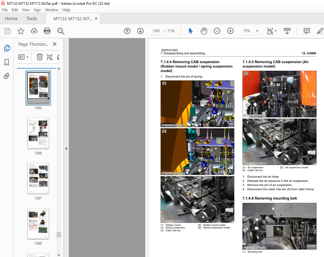
7 5 4 CAB suspension 12-84
8 Servicing 12-84
8 1 Air conditioning system 12-84
8 1 1 Compressor 12-84
13 K-OBD
GENERAL INFORMATION········ ········· ·· ···· ·········· ······ ······ ········ ···· ···· ······· ······ ··· ·· ·· ···· ··· ······· ··· ······ ···· ······ ··· ········· 13-1
1 Overview of K-OBD 13-1
2 Component of K-OBD kit 13-1
3 Structure of CANBUS line 13-3
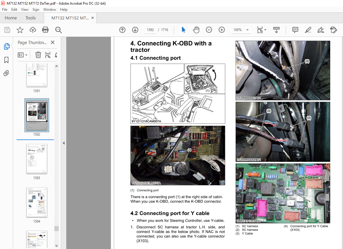
4 Connecting K-OBD with a tractor 13-5
4 1 Connecting port 13-5
4 2 Connecting port for Y cable 13-5
4 3 Connecting computer with tractor 13-5
4 4 Terminal position of K-OBD connector 13-6
INSTALLATION INFORMATION 13-7
1 Installing K-OBD 13-7
2 Updating K-OBD to the latest version software 13-7
3 Uninstalling K-OBD 13-8
OPERATION INFORMATION 13-11
1 User interface 13-11
2 Selecting tractor model 13-12
3 Logging in as different user level 13-12
4 Setting preferences 13-13
5 Getting help 13-13
6 Updating xCU 13-13
DIAGNOSTICS INFORMATION····· ····· ····· ·········· ····· ·· ············ ······· ··· ······· ···· ····· ····· ·· ··· ······· ·· ······· ····· ·· ······ ··· ···· 13-17
1 Overview of Diagnostics function 13-17
2 Function of Active DTC 13-17
3 Function of OTC history 13-18
4 Function of 1/0 testing 13-18
4 1 1/0 testing items 13-20
4 1 1 VCU1 table for 1/0 testing 13-20
4 1 2 VCU2 table for 1/0 testing 13-22
4 1 3 TCU-PST table for 1/0 testing 13-27
4 1 4 TCU-KVT table for 1/0 testing 13-28
4 1 5 VDC table for 1/0 testing 13-30
4 1 6 ARU/CEU/SWP table for 1/0 testing 13-33
5 Function of Calibration 13-37
5 1 Calibration table 13-38
5 2 Calibration value table 13-39
6 Function of Parameters 13-40
M7132 M7152,M71 72 DeTier XXV
KiSC issued 05, 2021 A
6 1 Parameters for xCU configuration 13-41
6 1 1 VCU 1 table for parameters 13-41
6 1 2 VCU2 table for parameters 13-42
6 1 3 ARU table for parameters 13-44
6 1 4 TCU-PST table for parameters 13-45
6 1 5 VDC table for parameters 13-46
6 1 6 TCU-KVT table for parameters 13-4 7
6 1 7 ECU table for parameters 13-48
6 1 8 ACU table for parameters (if equipped) 13-51
6 2 Parameters for SC replacement 13-53
6 3 Parameters for option parts 13-54
7 Function of Data Monitor 13-55
7 1 Selecting Data Monitor items 13-55
7 2 Monitoring multiple items on one chart 13-56
7 3 Starting a new session 13-56
7 4 Loading recorded data from file 13-57
7 5 Saving recording data to file 13-57
7 6 Deleting recorded data point 13-58
7 7 Stopping recording data points and resuming recording 13-58
7 8 Finish recording 13-58
7 9 Data Monitor items 13-60
7 9 1 VCU 1 table for Data Monitor 13-60
7 9 2 ECU Data Monitor table 13-61
7 9 3 ACU table for Data Monitor (if equipped) 13-64
8 Function of Active Test 13-66
8 1 Conducting active test 13-66
8 1 1 Cylinder injection stop instruction 13-67
8 1 2 Instruction of EGR valve on/off function (if equipped) 13-67
8 1 3 Instruction of glow relay on/off function 13-67
8 1 4 Instruction of intake throttle valve on/off function (if equipped) 13-68
8 1 5 Instruction of DEF recirculation line heater on/off function (if equipped) 13-68
8 1 6 Instruction of tank heater coolant valve on/off function 13-68
xxvi M71 32,M71 52,M71 72 ,DeTier
KiSC issued 05, 2021 A
More products