$34
Kubota Utility Vehicle RTV-XG850 Workshop Manual – PDF DOWNLOAD
Kubota Utility Vehicle RTV-XG850 Workshop Manual – PDF DOWNLOAD
FILE DETAILS:
Kubota Utility Vehicle RTV-XG850 Workshop Manual – PDF DOWNLOAD
Language : English
Pages : 392
Downloadable : Yes
File Type : PDF
Size: 207 MB
IMAGES PREVIEW OF THE MANUAL:
DESCRIPTION:
Kubota Utility Vehicle RTV-XG850 Workshop Manual – PDF DOWNLOAD
TO THE READER:
This Workshop Manual tells the servicing personnel about the mechanism. servicing and maintenance of the RW-
XG850. it contains 4 parts: “Information”, “General”, “Mechanism” and “Servicing”.
iNFORMATION
This section primarily contains information below.
– Safety First
. Safety Decal
– Specification
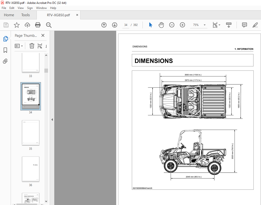
– Dimensions
GENERAL
This section primarily contains information below.
– Loader identification
° General Precautions
° Maintenance Check List
– Check and Maintenance
MECHANISM
This section contains information on the structure and the function of the unit. Before you continue with the
subsequent sections, make sure that you read this section.
SERVICING
This section primarily contains information below.
– Troubleshooting
– Service Specifications
– Tightening Torques
– Checking. Disassembling and Servicing
All illustrations. photographs and specifications contained in this manual are of the newest information available at the
time of publication.
KUBOTA reserves the right to change all information at any time without notice.
Since this manual includes many models, information or illustrations and photographs can show more than one
model.
TABLE OF CONTENTS:
Kubota Utility Vehicle RTV-XG850 Workshop Manual – PDF DOWNLOAD
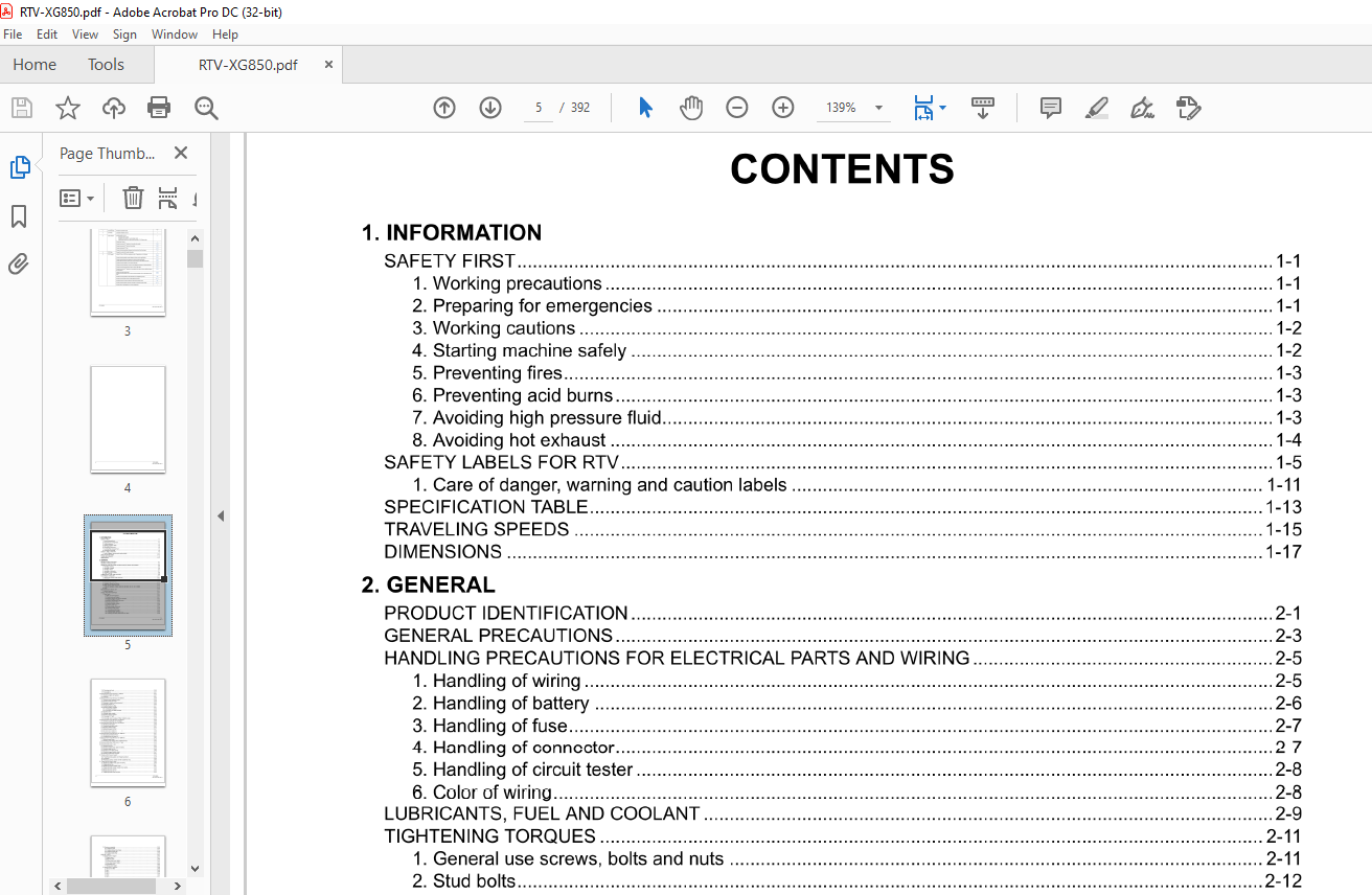
1 INFORMATION
SAFETY FIRST 1-1
1 Working precautions 1-1
2 Preparing for emergencies 1-1
3 Working cautions 1-2
4 Starting machine safely 1-2
5 Preventing fires 1-3
6 Preventing acid burns 1-3
7 Avoiding high pressure fluid 1-3
8 Avoiding hot exhaust 1-4
SAFETY LABELS FOR RTV 1-5
1 Care of danger, warning and caution labels 1-11
SPECIFICATION TABLE 1-13
TRAVELING SPEEDS 1-15
DIMENSIONS 1-17
2 GENERAL
PRODUCT IDENTIFICATION 2-1
GENERAL PRECAUTIONS 2-3
HANDLING PRECAUTIONS FOR ELECTRICAL PARTS AND WIRING 2-5
1 Handling of wiring 2-5
2 Handling of battery 2-6
3 Handling offuse 2-7
4 Handling of connector 2-7
5 Handling of circuit tester 2-8
6 Color of wiring 2-8
LUBRICANTS, FUEL AND COOLANT 2-9
TIGHTENING TORQUES 2-11
1 General use screws, bolts and nuts 2-11
2 Stud bolts 2-12
3 Hydraulic hose fittings 2-12
4 Hydraulic pipe cap nuts 2-13
5 Adapters, elbows and others 2-13
6 Metric screws, bolts and nuts 2-14
7 American standard screws, bolts and nuts with UNC or UNF threads 2-15
8 Plugs 2-15
MAINTENANCE CHECK LIST 2-17
1 Service intervals 2-17
CHECK AND MAINTENANCE 2-21
1 Daily check 2-21
RTV-XG850
1 1 Walk around inspection 2-21
1 2 Checking around engine 2-21
1 3 Checking amount of fuel and refueling 2-21
1 4 Checking engine oil level 2-22
1 5 Checking transmission fluid level 2-23
1 6 Checking coolant level 2-23
1 7 Cleaning radiator screen 2-24
1 8 Checking drain cap 2-24
1 9 Checking brake fluid level 2-24
1 10 Checking brake pedal 2-25
1 11 Checking parking brake 2-25
1 12 Checking Easy Checker™ 2-25
1 13 Checking head light, and so on 2-25
1 14 Checking seat belt, ROPS and door latch 2-26
iii
KiSC issued 08, 2021 A
1 15 Checking joint boot 2-26
1 16 Checking tire inflation pressure 2-26
1 17 Checking tire 2-27
2 Check points of every 50 hours or 1500 km 2-27
2 1 Checking engine start system 2-27
2 2 Greasing 2-27
3 Check points of every 100 hours or 3000 km 2-29
3 1 Checking wheel fastener torque 2-29
3 2 Checking brake pad wear 2-29
3 3 Cleaning air cleaner primary element 2-30
3 4 Changing engine oil 2-30
3 5 Checking fuel pump filter 2-31
3 6 Checking battery condition 2-31
3 6 1 Charging the battery 2-32
3 6 2 Directions for battery storage 2-33
3 7 Adjusting toe-in 2-33
3 8 Cleaning spark arrester 2-34
3 9 Checking exhaust system 2-35
3 10 Checking CVT belt 2-35
3 11 Checking the transmission gear shift sensor 2-35
3 12 Checking carbon canister air filter (California only) 2-35
4 Check points of every 200 hours or 3000 km 2-36
4 1 Checking suspension arm bushings 2-36
5 Check points of every 200 hours or 6000 km 2-36
5 1 Checking brake pedal 2-36
5 2 Checking brake light switch 2-37
5 3 Adjusting parking brake 2-37
5 4 Replacing engine oil filter 2-37
5 5 Checking spark plug condition and gap 2-38
5 6 Checking valve clearance 2-39
6 Check points of every 400 hours or 12000 km 2-41
6 1 Changing transmission fluid 2-41
6 2 Changing front axle case oil 2-42
7 Check points of every 500 hours or 15000 km 2-42
7 1 Replacing spark plug 2-42
7 2 Checking purge control valve (California only) 2-42
8 Check points of every 1000 hours or 1 year 2-42
8 1 Replacing air cleaner primary element and secondary element 2-42
9 Check points of every 1 year 2-43
9 1 Checking fuel line 2-43
9 2 Checking radiator hose, pipe and clamp 2-45
9 3 Checking intake air line 2-46
9 4 Checking CVT intake air line 2-46
9 5 Checking engine breather hose 2-47
9 6 Checking brake hose and pipe 2-47
10 Check points of every 2 years 2-48
10 1 Changing brake fluid 2-48
10 2 Flushing cooling system and changing coolant 2-48
10 3 Antifreeze 2-49
10 4 Replacing carbon canister air filter (California only) 2-50
11 Check point of every 4 years 2-50
11 1 Replacing radiator hose, pipe and clamp 2-50
11 2 Replacing fuel line 2-51
11 3 Replacing engine breather hose 2-51
11 4 Replacing brake master cylinder (inner parts) 2-52
11 5 Replacing brake caliper (inner parts) 2-52
11 6 Replacing intake air line 2-52
11 7 Replacing brake hose and pipe 2-53
iv RTV-XG850
KiSC issued 08, 2021 A
12 Service as required 2-53
12 1 Replacing fuse 2-53
12 2 Replacing slow-blow fuses 2-54
12 3 Replacing light bulb 2-55
12 4 Replacing fuel filter 2-55
SPECIAL TOOLS 2-57
1 Special tools for engine 2-57
1 1 Engine stand 2-57
1 2 Magneto puller 2-60
1 3 Driven pulley lever (plate) 2-62
1 4 Driven pulley lever ( square pipe) 2-63
1 5 Cam chain tension holder 2-63
1 6 Crankshaft lock 2-64
1 7 Timing chain holder 2-65
2 Special tools for machine 2-66
2 1 Tie-rod end lifter 2-66
2 2 Jig 1 2-66
2 3 Jig 2 2-66
2 4 Jig 3 2-66
2 5 Jig 4 2-67
2 6 Jig 5 2-67
TIRES AND WHEELS 2-69
1 Tires 2-69
1 1 Tire pressure 2-69
1 1 1 Checking tire inflation pressure 2-69
1 2 Type oftires 2-69
1 2 1 Tire type and use 2-69
1 3 Wheels 2-70
1 4 Shock absorbers 2-70
1 4 1 Shock absorber spring adjustment 2-70
2 Cargo bed 2-71
2 1 Cargo bed general caution 2-71
2 2 Max cargo load 2-71
3 Vehicle limitations 2-73
3 ENGINE
MECHANISM 3-1
1 Engine body 3-1
1 1 Function of cylinder head 3-1
1 2 Function of camshaft 3-1
1 3 Function of cylinder 3-1
1 4 Function of crankcase and oil pan 3-2
1 5 Function of piston 3-2
1 6 Function of connecting rod 3-3
1 7 Function of crankshaft 3-3
1 8 Function of balancer 3-3
1 9 Function of flywheel 3-3
2 Lubricating system 3-5
2 1 Structure of lubricating system 3-5
2 2 Function of oil pump 3-6
2 3 Function of oil filter and relief valve 3-6
3 Cooling system 3-7
RTV-XG850
3 1 Outline of cooling system 3-7
3 2 Structure of cooling system 3-8
3 3 Function of water pump 3-10
3 4 Function of thermostat 3-10
3 5 Function of radiator 3-10
3 6 Function of radiator cap 3-11
V
KiSC issued 08, 2021 A
4 Fuel system 3-12
4 1 Structure of electronic fuel injection system 3-12
4 2 Outline of multi-point injection (MPI) system 3-14
4 2 1 Function of ISC (idle speed control) 3-15
4 2 2 Function of throttle position sensor 3-15
4 2 3 Function of TMAP sensor 3-15
4 2 4 Function of 02 sensor 3-15
4 2 5 Function of coolant temperature sensor 3-16
4 2 6 Function of crankshaft position sensor 3-16
4 3 Structure of fuel system 3-17
4 4 Structure of EVAPO system (If equipped) 3-18
4 5 Structure of intake system 3-19
SERVICING 3-21
1 Troubleshooting for engine 3-21
1 1 Diagnostic trouble code for engine ECU 3-24
2 Service specifications for engine 3-26
3 Tightening torques for engine 3-29
4 Exhaust valve shim guide 3-33
5 Intake valve shim guide 3-34
6 Checking and adjusting 3-35
6 1 Engine body 3-35
6 1 1 Checking compression pressure 3-35
6 1 2 Checking valve clearance 3-35
6 1 3 Adjusting exhaust valve clearance 3-38
6 1 4 Adjusting intake valve clearance 3-39
6 2 Lubricating system 3-40
6 2 1 Checking oil pressure 3-40
6 3 Cooling system 3-41
6 3 1 Checking radiator cap air leakage 3-41
6 3 2 Checking radiator water leakage 3-41
6 3 3 Checking thermostat valve opening temperature 3-42
6 4 Fuel system 3-42
6 4 1 Checking fuel pump pressure 3-42
6 4 2 Checking engine speed and traveling speed 3-42
6 4 3 Adjusting engine speed and traveling speed 3-43
7 Disassembling and assembling 3-45
7 1 Removing engine and transmission 3-45
7 1 1 Draining engine oil 3-45
7 1 2 Draining coolant 3-46
7 1 3 Draining transmission fluid 3-4 7
7 1 4 Removing CVT hoses 3-4 7
7 1 5 Removing battery 3-4 7
7 1 6 Removing cargo bed 3-48
7 1 7 Removing doors 3-49
7 1 8 Removing seats 3-49
7 1 9 Removing center box cover and lower center cover 3-50
7 1 10 Removing exhaust covers 3-50
7 1 11 Removing air cleaner assembly 3-51
7 1 12 Removing skid plates 3-51
7 1 13 Removing rear wheel 3-52
7 1 14 Removing rear brake hose and rear brake pipe 3-52
7 1 15 Removing rear shock absorber 3-53
7 1 16 Removing rear drive shaft 3-53
7 1 17 Disconnecting cables 3-54
7 1 18 Disconnecting radiator hose 3-54
7 1 19 Disconnecting engine wiring harness 3-55
7 1 20 Disconnecting transmission wire harness 3-56
7 1 21 Disconnecting EVAPO hose (If equipped) 3-56
vi RTV-XG850
KiSC issued 08, 2021 A
7 1 22 Disconnecting fuel hose 3-56
7 1 23 Disconnecting propeller shaft 3-56
7 1 24 Removing engine and transmission assembly 3-57
7 1 25 Removing transmission frame 3-57
7 2 Separating engine from transmission 3-58
7 2 1 Removing CVT cover 3-58
7 2 2 Removing CVT driven fan 3-59
7 2 3 Removing CVT bracket and movable drive pulley 3-59
7 2 4 Removing CVT weight rollers 3-61
7 2 5 Removing CVT belt and drive pulley 3-62
7 2 6 Removing driven pulley 3-62
7 2 7 Removing CVT inside cover 3-63
7 2 8 Removing 4WD shaft 3-63
7 2 9 Removing transmission brackets 3-64
7 3 Disassembling engine 3-64
7 3 1 Removing exhaust pipe 3-64
7 3 2 Removing intake pipe assembly 3-64
7 3 3 Removing thermostat and bypass hose 3-65
7 3 4 Removing centrifugal clutch 3-65
7 3 5 Removing oil filter and oil gauge pipe 3-67
7 3 6 Removing water pump case 3-67
7 3 7 Removing magneto cover and reduction gear 3-69
7 3 8 Removing flywheel and starting gear 3-70
7 3 9 Removing ignition coils and spark plugs 3-72
7 3 10 Removing head cover 3-72
7 3 11 Removing camshafts and timing chain 3-73
7 3 12 Removing cylinder head 3-75
7 3 13 Removing timing chain lever and timing chain guide 3-76
7 3 14 Removing water pump shaft 3-76
7 3 15 Removing starter assembly 3-77
7 3 16 Removing oil pan 3-77
7 3 17 Removing oil pump 3-78
7 3 18 Removing lower crankcase 3-78
7 3 19 Removing balancer shaft 3-80
7 3 20 Removing crankshaft 3-80
7 3 21 Removing cylinder 3-81
7 3 22 Removing connecting rods and pistons 3-82
8 Servicing 3-82
RTV-XG850
8 1 Cylinder head and valve 3-82
8 1 1 Checking cylinder head surface flatness 3-82
8 1 2 Checking cylinder surface flatness 3-82
8 1 3 Checking clearance between valve stem and valve guide 3-83
8 1 4 Checking valve seat width 3-83
8 1 5 Correcting valve angle 3-84
8 1 6 Correcting valve seat angle 3-84
8 1 7 Lapping valves 3-84
8 1 8 Checking valve spring free length and tilt 3-85
8 1 9 Checking valve spring setting load 3-85
8 2 Camshaft 3-85
8 2 1 Checking cam height 3-85
8 2 2 Checking camshaft journal clearance 3-86
8 3 Piston 3-86
8 3 1 Checking piston ring groove clearance 3-86
8 3 2 Checking piston ring gap 3-87
8 3 3 Checking piston pin outer diameter 3-87
8 4 Crankshaft 3-87
8 4 1 Checking crankshaft alignment 3-87
8 4 2 Checking clearance between crankshaft journal and bearing 3-88
vii
KiSC issued 08, 2021 A
8 4 3 Checking clearance between crankpin and connecting rod 3-88
8 4 4 Replacing crankshaft bearings 3-89
8 4 5 Replacing connecting rod bearings 3-90
8 4 6 Checking crankshaft side clearance 3-91
8 4 7 Checking connecting rod side clearance 3-91
8 5 Cylinder 3-91
8 5 1 Checking clearance between cylinder and piston 3-91
8 6 Oil pump 3-92
8 6 1 Checking clearance between inner rotor and outer rotor 3-92
8 6 2 Checking clearance between outer rotor and pump body 3-92
4 TRANSMISSION
MECHANISM 4-1
1 Structure of transaxle 4-1
2 Structure of CVT (Continuously variable transmission) 4-2
3 Structure of range gear shift 4-3
4 Structure of front wheel drive 4-5
5 Structure of differential lock 4-7
SERVICING 4-9
1 Troubleshooting for transmission 4-9
2 Service specifications for transaxle 4-11
3 Tightening torques for transmission 4-12
4 Checking and adjusting 4-14
4 1 Checking range gear shift lever position (Adjusting the shift cable length and the select cable
length) 4-14
4 2 Checking four wheel drive lever position (Adjusting the 4WD shift cable length) 4-14
4 3 Checking differential lock cable (Adjusting the length of the cable for differential lock) 4-15
4 4 Checking differential interlocking spring (Adjusting the differential interlocking spring length) 4-16
4 5 Checking CVT belt 4-16
5 Disassembling and assembling 4-17
5 1 Removing engine and transmission 4-17
5 1 1 Draining engine oil 4-17
5 1 2 Draining coolant 4-18
5 1 3 Draining transmission fluid 4-19
5 1 4 Removing CVT hoses 4-19
5 1 5 Removing battery 4-20
5 1 6 Removing cargo bed 4-20
5 1 7 Removing doors 4-21
5 1 8 Removing seats 4-21
5 1 9 Removing center box cover and lower center cover 4-22
5 1 10 Removing exhaust covers 4-22
5 1 11 Removing air cleaner assembly 4-23
5 1 12 Removing skid plates 4-23
5 1 13 Removing rear wheel 4-24
5 1 14 Removing rear brake hose and rear brake pipe 4-24
5 1 15 Removing rear shock absorber 4-25
5 1 16 Removing rear drive shaft 4-25
5 1 17 Disconnecting cables 4-26
5 1 18 Disconnecting radiator hose 4-26
5 1 19 Disconnecting engine wiring harness 4-27
5 1 20 Disconnecting transmission wire harness 4-28
5 1 21 Disconnecting fuel hose 4-28
5 1 22 Disconnecting propeller shaft 4-28
5 1 23 Removing engine and transmission assembly 4-28
5 1 24 Removing transmission frame 4-29
5 2 Separating engine from transmission 4-30
5 2 1 Removing CVT cover 4-30
5 2 2 Removing CVT driven fan 4-30
viii RTV-XG850
KiSC issued 08, 2021 A
5 2 3 Removing CVT bracket and movable drive pulley 4-31
5 2 4 Removing CVT weight rollers 4-33
5 2 5 Removing CVT belt and drive pulley 4-34
5 2 6 Removing driven pulley 4-34
5 2 7 Removing CVT inside cover 4-35
5 2 8 Removing 4WD shaft 4-35
5 2 9 Removing transmission brackets 4-36
5 3 Disassembling transmission 4-36
5 3 1 Removing shift lever and differential lock lever 4-36
5 3 2 Removing transaxle case cover 4-36
5 3 3 Removing parking brake 4-37
5 3 4 Removing 1 st shaft assembly 4-37
5 3 5 Removing drum shift cam 4-38
5 3 6 Removing 2nd shaft assembly and 3rd shaft assembly 4-39
5 3 7 Removing differential lock assembly 4-39
5 3 8 Removing OT shaft assembly 4-40
5 3 9 Removing 4th shaft assembly 4-41
6 Servicing 4-42
6 1 Checking cable 4-42
6 2 Checking transaxle frame and rubber bushing 4-42
6 3 Checking CVT weight roller 4-43
6 4 Checking CVT spacer 4-43
6 5 Checking bearing 4-44
6 6 Checking gear 4-44
6 7 Checking range gear shaft and needle bearing 4-44
6 8 Checking backlash between differential pinion and differential side gear 4-44
6 9 Checking brake disk and friction plate wear 4-45
5 SUSPENSION
MECHANISM 5-1
1 Structure of suspension 5-1
SERVICING 5-3
1 Troubleshooting for suspension 5-3
2 Tightening torques for suspension 5-4
3 Checking and adjusting 5-5
3 1 Checking shock absorber 5-5
3 2 Adjusting shock absorber spring 5-5
3 3 Checking rear knuckle case 5-5
4 Disassembling and assembling 5-6
4 1 Rear shock absorber 5-6
4 1 1 Disconnecting negative battery cable 5-6
4 1 2 Removing cargo bed 5-6
4 1 3 Removing rear wheel 5-7
4 1 4 Removing rear shock absorber 5-7
4 2 Front shock absorber 5-7
4 2 1 Removing front wheel 5-7
4 2 2 Removing front upper cover 5-8
4 2 3 Removing front shock absorber 5-8
5 Servicing 5-9
5 1 Removing shock absorber spring 5-9
6 BRAKES
MECHANISM 6-1
1 Outline of traveling brake 6-1
2 Structure of traveling brake 6-2
2 1 Outline of automatic brake adjustment 6-3
3 Outline of master cylinder 6-4
4 Outline of brake oil 6-5
RTV-XG850 ix
KiSC issued 08, 2021 A
5 Outline of parking brake 6-6
SERVICING 6-7
1 Troubleshooting for brakes 6-7
2 Service specifications for brakes 6-9
3 Tightening torques for brakes 6-10
4 Checking and adjusting 6-11
4 1 Brake pedal 6-11
4 1 1 Adjusting brake pedal 6-11
4 2 Brake fluid 6-11
4 2 1 Checking brake fluid level 6-11
4 2 2 Changing brake fluid 6-12
4 2 3 Bleeding brake lines 6-13
4 3 Brake pad 6-14
4 3 1 Checking brake pad wear 6-14
4 4 Parking brake 6-14
4 4 1 Adjusting parking brake 6-14
5 Disassembling and assembling 6-15
5 1 Master cylinder 6-15
5 1 1 Removing master cylinder assembly 6-15
5 1 2 Removing master cylinder inner parts 6-15
5 2 Front brake pad 6-16
5 2 1 Removing front wheel 6-16
5 2 2 Replacing front brake pad 6-17
5 3 Front brake caliper 6-17
5 3 1 Removing front wheel 6-17
5 3 2 Removing front brake caliper 6-18
5 4 Front knuckle assembly 6-18
5 4 1 Removing front wheel and front axle nut 6-18
5 4 2 Disconnecting tie-rod end 6-20
5 4 3 Removing front brake caliper 6-20
5 4 4 Removing knuckle assembly 6-21
5 5 Front brake disc 6-21
5 5 1 Removing front wheel and front axle nut 6-21
5 5 2 Disconnecting tie-rod end 6-23
5 5 3 Removing front brake caliper 6-23
5 5 4 Removing knuckle assembly 6-24
5 5 5 Removing front knuckle arm and bearing 6-24
5 5 6 Removing front brake disc and inner ring of bearing 6-26
5 6 Rear brake pad 6-27
5 6 1 Removing rear wheel 6-27
5 6 2 Replacing rear brake pad 6-27
5 7 Rear brake caliper 6-28
5 7 1 Removing rearwheel 6-28
5 7 2 Removing rear brake caliper 6-28
5 8 Rear knuckle assembly 6-28
5 8 1 Removing rear wheel 6-28
5 8 2 Removing rear brake caliper 6-29
5 8 3 Removing rear knuckle assembly 6-29
5 9 Rear brake disc 6-30
5 9 1 Removing rear wheel 6-30
5 9 2 Removing rear brake caliper 6-30
5 9 3 Removing rear knuckle assembly 6-30
5 9 4 Removing rear knuckle arm and bearing 6-31
5 9 5 Removing rear brake disc and inner ring of bearing 6-33
6 Servicing 6-33
6 1 Brake disc 6-33
6 1 1 Checking brake disc wear 6-33
6 1 2 Checking brake disc alignment 6-34
X RTV-XG850
KiSC issued 08, 2021 A
6 2 Brake caliper 6-34
6 2 1 Checking brake caliper inner parts 6-34
7 FRONT AXLE
MECHANISM 7-1
1 Structure of front axle 7-1
2 Structure of limited slip differential (LSD) 7-2
3 Operation of limited slip differential (LSD) 7-3
SERVICING 7-5
1 Troubleshooting for front axle 7-5
2 Service specifications for front axle 7-6
3 Tightening torques for front axle 7-7
4 Checking and adjusting 7-8
4 1 Checking toe-in 7-8
4 2 Adjusting toe-in 7-8
5 Disassembling and assembling 7-8
5 1 Knuckle case 7-8
5 1 1 Removing front wheel and front axle nut 7-8
5 1 2 Removing front brake caliper 7-9
5 1 3 Disconnecting tie-rod end 7-10
5 1 4 Removing knuckle assembly 7-11
5 2 Front differential case assembly 7-11
5 2 1 Removing front wheel and front axle nut 7-11
5 2 2 Draining front axle case oil 7-13
5 2 3 Removing front brake caliper 7-1 3
5 2 4 Disconnecting tie-rod end 7-14
5 2 5 Removing knuckle assembly 7-14
5 2 6 Removing upper arm and disconnecting propeller shaft 7-15
5 2 7 Removing front differential case 7-16
6 Servicing 7-19
6 1 Checking bearing 7-19
6 2 Checking turning torque of bevel pinion shaft 7-19
6 3 Checking tooth contact between bevel pinion shaft and bevel gear 7-20
6 4 Checking backlash between bevel pinion shaft and bevel gear 7-21
8 STEERING
MECHANISM 8-1
1 Structure of electronic power steering 8-1
SERVICING 8-3
1 Troubleshooting for steering 8-3
1 1 Diagnostic trouble code for EPS ECU 8-4
2 Service specifications for steering 8-6
3 Tightening torques for steering 8-7
4 Checking and adjusting 8-8
4 1 Adjusting stopper bolt 8-8
5 Disassembling and assembling 8-8
RTV-XG850
5 1 Removing electric power steering (EPS) motor 8-8
5 1 1 Disconnecting negative battery cable 8-8
5 1 2 Removing bonnet 8-8
5 1 3 Removing doors 8-9
5 1 4 Removing ROPS 8-9
5 1 5 Removing steering wheel 8-10
5 1 6 Removing panel 8-10
5 1 7 Removing universal joint (intermediate shaft) 1 8-10
5 1 8 Removing EPS motor 8-11
5 2 Removing rack and pinion 8-12
5 2 1 Removing front wheel 8-12
5 2 2 Disconnecting tie-rod end 8-1 3
xi
KiSC issued 08, 2021 A
5 2 3 Removing rack and pinion 8-13
9 ELECTRICAL SYSTEM
MECHANISM 9-1
1 Location of electrical components 9-1
2 Starting system 9-2
2 1 Function of key switch 9-2
2 2 Function of starter solenoid 9-2
2 3 Outline of starter 9-2
2 4 Outline of neutral safety switch 9-3
2 5 Location of relay 9-3
3 Charging system 9-3
3 1 Function of charge coil 9-3
3 2 Function of regulator 9-4
4 Lighting system 9-4
4 1 Function of head light switch 9-4
4 2 Outline of brake lamp switch 9-4
5 Cooling system 9-4
5 1 Outline of fan motor 9-4
5 2 Outline of coolant temperature sensor 9-5
6 Gauge system 9-5
6 1 Function of fuel level sensor 9-5
6 2 Outline of traveling speed sensor 9-5
7 Meter panel 9-5
7 1 Outline of Easy CheckerT” 9-5
8 Others 9-6
8 1 Outline of 12 V electric outlet 9-6
SERVICING 9-7
1 Troubleshooting for electrical system 9-7
1 1 Diagnostic trouble code for electrical system 9-11
2 Service specifications for electrical system 9-12
3 Checking and adjusting 9-13
3 1 Battery 9-13
3 1 1 Checking battery voltage 9-13
3 1 2 Checking battery terminal connection 9-13
3 1 3 Checking battery condition 9-13
3 1 4 Charging the battery 9-14
3 2 Key switch 9-15
3 2 1 Removing key switch 9-15
3 2 2 Checking key switch connector voltage 9-15
3 2 3 Checking key switch continuity at off position 9-15
3 2 4 Checking key switch continuity at on position 9-16
3 2 5 Checking key switch continuity at start position 9-16
3 3 Spark plug 9-16
3 3 1 Checking spark plug spark 9-16
3 4 Starter 9-17
3 4 1 Checking starter motor 9-17
3 4 2 Checking starter solenoid continuity 9-17
3 5 Safety switch 9-18
3 5 1 Checking neutral safety switch continuity 9-18
3 5 2 Checking shift switch continuity 9-18
3 6 Relays 9-19
3 6 1 Checking relay continuity 9-19
3 7 Charging system 9-19
3 7 1 Checking stator continuity 9-19
3 7 2 Checking regulator voltage 9-20
3 8 Lighting system 9-20
3 8 1 Removing combination switch 9-20
xii RTV-XG850
KiSC issued 08, 2021 A
RTV-XG850
3 8 2 Checking combination switch connector voltage 9-20
3 8 3 Checking head light switch continuity when setting switch at off position 9-20
3 8 4 Checking head light switch continuity when setting switch at low position 9-21
3 8 5 Checking head light switch continuity when setting switch at high position 9-21
3 8 6 Checking engine oil pressure lamp 9-21
3 8 7 Checking engine oil pressure switch continuity 9-22
3 8 8 Checking engine oil pressure switch connector voltage 9-22
3 8 9 Checking parking brake switch continuity 9-23
3 8 10 Checking parking brake switch panel and wiring harness 9-23
3 8 11 Checking 4WD switch continuity 9-24
3 8 12 Checking brake lamp switch continuity 9-24
3 9 Cooling system 9-25
3 9 1 Checking front radiator fan motor 9-25
3 10 Gauges 9-25
3 10 1 Checking fuel level sensor continuity 9-25
3 10 2 Checking traveling speed sensor connector voltage 9-27
3 11 Others 9-27
3 11 1 Checking horn switch connector voltage 9-27
3 11 2 Checking horn switch continuity 9-28
3 12 EFI system 9-29
3 12 1 Checking ECU harness connector 9-29
3 12 2 Checking ECU connector voltage 9-31
3 12 3 Checking coolant temperature sensor connector 9-31
3 12 4 Checking coolant temperature sensor 9-32
3 12 5 Checking injector harness connector 9-32
3 12 6 Checking injector 9-33
3 12 7 Checking TMAP sensor harness connector 9-33
3 12 8 Checking TMAP sensor 9-34
3 12 9 Checking ignition coil harness connector 9-34
3 12 10 Checking ignition coil 9-35
3 1 2 11 Checking throttle position sensor harness connector 9-36
3 12 12 Checking throttle position sensor 9-36
3 12 13 Checking ISC (idle speed control) harness connector 9-37
3 12 14 Checking ISC (idle speed control) 9-38
3 12 15 Checking pulsar coil harness connector 9-39
3 12 16 Checking pulsar coil 9-40
3 12 17 Checking fuel pump harness connector 9-41
3 12 18 Checking fuel pump 9-41
3 12 19 Checking 02 sensor harness connector 9-42
3 12 20 Checking 02 sensor 9-43
3 13 EVAPO system (If equipped) 9-44
3 13 1 Checking purge control valve harness connector (If equipped) 9-44
More products