$36
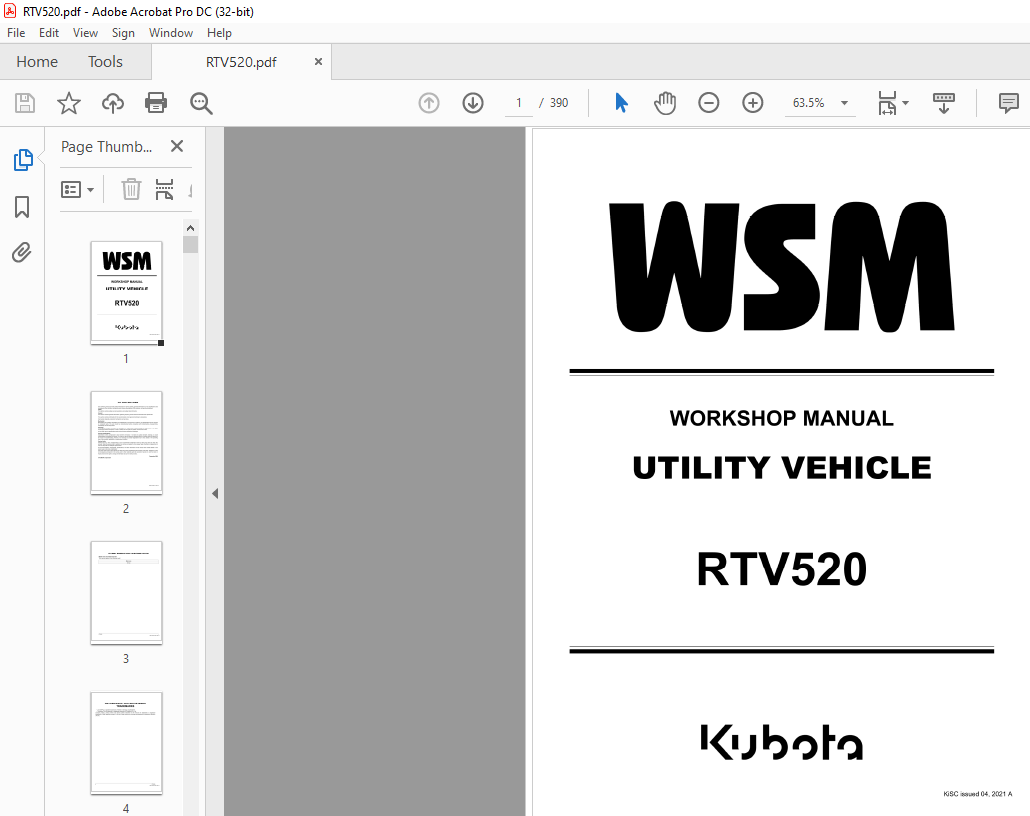
Kubota Utility Vehicle RTV520 Workshop Manual – PDF DOWNLOAD
Kubota Utility Vehicle RTV520 Workshop Manual – PDF DOWNLOAD
FILE DETAILS:
Kubota Utility Vehicle RTV520 Workshop Manual – PDF DOWNLOAD
Language : English
Pages : 390
Downloadable : Yes
File Type : PDF
Size: 192 MB
IMAGES PREVIEW OF THE MANUAL:
DESCRIPTION:
Kubota Utility Vehicle RTV520 Workshop Manual – PDF DOWNLOAD
TO THE READER:
This workshop manual provides safety information for service activity, general information such as specifications and
dimensions of the machine, mechanisms and structure descriptions of the machine, and service procedures.
Safety
This section contains safety service descriptions and safety label information.
General
This section contains general instructions, tightening torques, general machine information and special tools.
Maintenance
This section contains information for the recommended oil and general maintenance procedures.
Each section basically consists of mechanism and servicing.
Mechanism
Mechanism part contains information and explanations for the structure, functions, and specifications of the machine
or component parts. This part should be comprehended before proceeding with troubleshooting, disassembling,
assembling, and servicing works.
Servicing
Servicing part contains information and procedures for maintenance, troubleshooting and repair works. The reader
should follow these instructions in order to satisfy any servicing work safely, correctly and quickly.
In this WSM, service specifications and service limits are defined as followings.
Service specifications:
Specification which corresponds to new machine’s ex-factory. It is based on quality standard, drawings, or actual
measurements conducted by Kubota . This value is used to determine whether there is a problem with the machine in
the event of a troubleshooting. However, it is necessary to consider degradation due to wear, based on the operating
time of the machine, application or maintenance condition.
Service limits:
Service limit is a value corresponding to the recommended performance limit by taking long term-use wear into
account. When the service limit is reached , the machine is required to have proper repair, overhaul or replacement in
order to keep safe and adequate performance.
All of the illustrations, photographs, specifications, and other information in this manual were created based on the
latest model at the time of publication.
The parts names used in this manual are unified into names representing the functions of the parts. Therefore, ii does
not necessarily correspond to the names used in other materials (parts list, operators manual etc.) and the name on
the label / identification plates on the product.
Kubota reserves the right to change all information at any time without notice.
TABLE OF CONTENTS:
Kubota Utility Vehicle RTV520 Workshop Manual – PDF DOWNLOAD
1 SAFETY
SAFETY FIRST 1-1
1 Working precautions 1-1
2 Preparing for emergencies 1-1
3 Working cautions 1-2
4 Starting machine safely 1-2
5 Preventing fires 1-3
6 Preventing acid burns 1-3
7 Avoiding high pressure fluid 1-3
8 Avoiding hot exhaust 1-4
SAFETY LABELS 1-5
1 Care of safety labels 1-11
2 GENERAL
GENERAL PRECAUTIONS 2-1
TIGHTENING TORQUES 2-3
1 General use screws, bolts and nuts 2-3
2 Stud bolts 2-4
3 Hydraulic fittings 2-5
3 1 Hydraulic hose fittings 2-5
3 2 Hydraulic pipe cap nuts 2-5
3 3 Adapters, elbows and others 2-5
4 Metric screws, bolts and nuts 2-6
5 American standard screws, bolts and nuts with UNC or UNF threads 2-6
6 Plugs 2-6
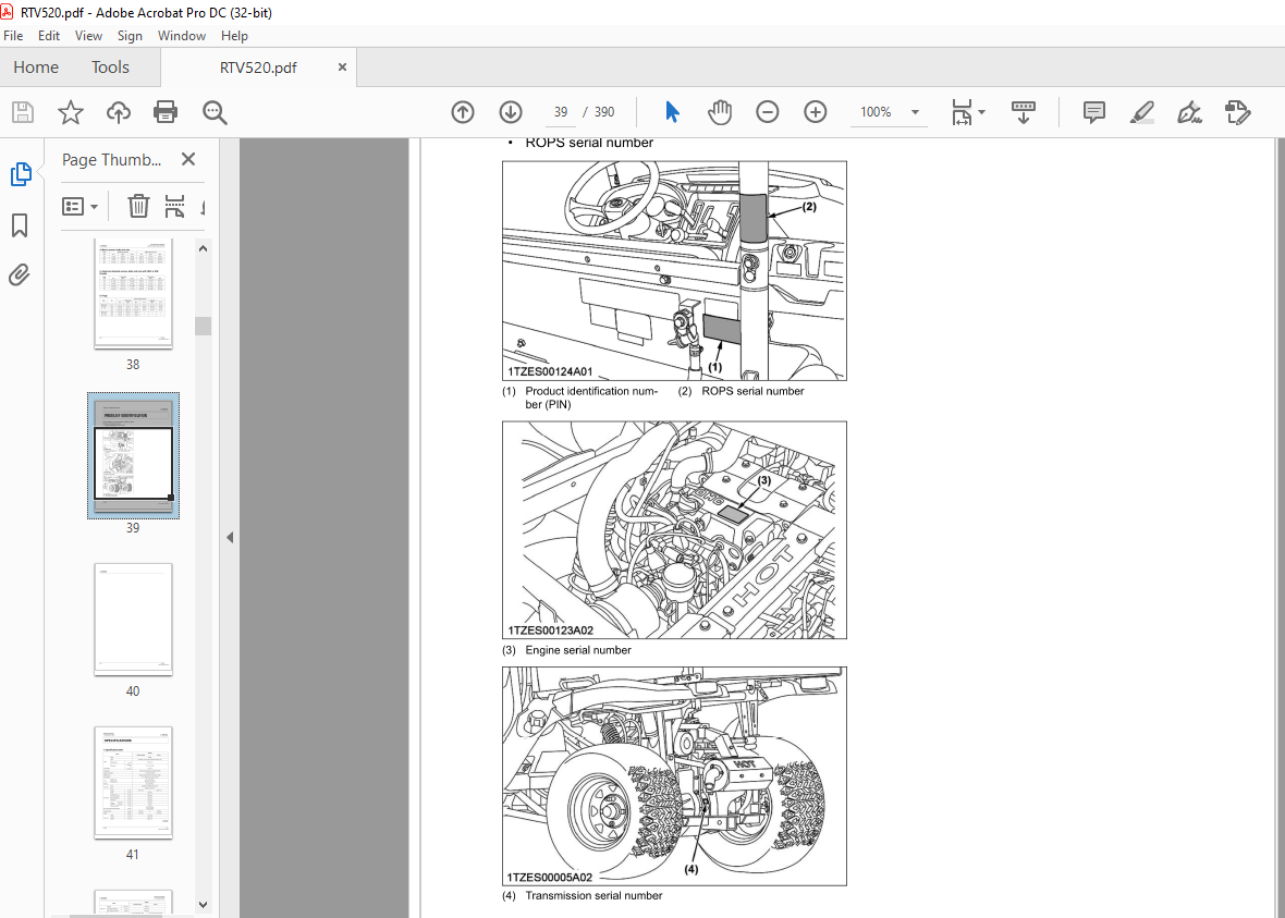
PRODUCT IDENTIFICATION 2-7
SPECIFICATIONS 2-9
1 Specification table 2-9
2 Traveling speeds 2-10
DIMENSIONS 2-11
HANDLING PRECAUTIONS FOR ELECTRICAL PARTS AND WIRING 2-13
1 Handling wire harness 2-13
2 Handling the battery 2-14
3 Handling fuses 2-15
4 Handling connectors 2-15
5 Wiring color 2-16
6 Handling of circuit tester 2-16
TIRES AND WHEELS 2-17
1 Tires 2-17
1 1 Inflation pressure 2-17
1 2 Tire type and use 2-17
2 Wheels 2-17
3 Shock absorbers 2-18
3 1 Rear shock absorber spring adjustment 2-18
VEHICLE LIMITATIONS 2-19
SPECIAL TOOLS 2-21
RTV520
1 Special tools for machine 2-21
1 1 Tie rod end lifter 2-21
1 2 Relief valve pressure tester 2-21
1 3 Hydrostatic transmission tester and HST adapter set 2-21
1 4 Lower arm bush tool 2-22
1 5 Jig base 2-24
1 6 Jig 1 2-26
1 7 Jig 2 2-27
V
KiSC issued 04, 2021 A
1 8 Jig 3 2-28
1 9 Check and high pressure relief valve assembly tool 2-29
2 Special tools for engine 2-31
2 1 Compression tester 2-31
2 2 Flywheel stopper 2-32
2 3 Engine stand 2-34
3 MAINTENANCE
SERVICE INTERVALS 3-1
LUBRICANTS, FUEL AND COOLANT 3-5
CHECK AND MAINTENANCE 3-7
1 Daily check 3-7
1 1 Walk around inspection 3-7
1 2 Checking amount of fuel and refueling 3-7
1 3 Checking engine oil level 3-8
1 4 Checking transmission fluid level 3-9
1 5 Checking coolant level 3-9
1 6 Cleaning radiator screen 3-10
1 7 Checking ECU cooling fan 3-10
1 8 Checking brake fluid level 3-10
1 9 Checking brake pedal 3-11
1 10 Checking parking brake 3-11
1 11 Checking gauges, meter and Easy Checker™ 3-11
1 12 Checking head lights, tail lights and other lights (if equipped) 3-12
1 13 Checking seat belt and ROPS 3-12
1 14 Checking joint boots 3-12
1 15 Checking tire inflation pressure 3-12
2 Check points every 50 hours 3-12
2 1 Greasing 3-12
2 2 Checking engine start system 3-13
3 Check points of every 100 hours 3-14
3 1 Checking VHT neutral spring 3-14
3 2 Checking wheel bolt torque 3-14
3 3 Cleaning air cleaner primary element 3-14
3 4 Cleaning pre cleaner element 3-15
3 5 Adjusting alternator drive belt tension 3-15
3 6 Checking carbon canister air filter 3-16
3 7 Checking battery condition 3-16
3 7 1 Charging the battery 3-17
3 7 2 Directions for battery storage 3-17
3 8 Adjusting toe-in 3-17
3 9 Cleaning spark arrester 3-18
4 Check points of every 200 hours 3-18
4 1 Adjusting parking brake lever 3-18
4 2 Replacing engine oil filter 3-19
4 3 Changing engine oil 3-19
4 4 Cleaning radiator cooling fins 3-20
4 5 Replacing transmission oil filter 3-21
4 6 Checking spark plug condition and gap 3-22
4 7 Checking brake pedal 3-22
4 8 Checking brake light switch 3-23
5 Check points of every 300 hours 3-23
5 1 Checking tire 3-23
6 Check points of every 400 hours 3-23
6 1 Changing transmission oil 3-23
6 2 Changing front axle case oil 3-24
7 Check points of every 500 hours 3-24
7 1 Checking engine timing belt 3-24
vi RTV520
KiSC issued 04, 2021 A
8 Check points of every 1000 hours 3-24
8 1 Replacing engine timing belt 3-24
8 2 Adjusting engine valve clearance 3-25
8 3 Cleaning engine combustion chamber 3-25
9 Check points of every 1000 hours or 1 year 3-25
9 1 Replacing air cleaner primary element and secondary element 3-25
9 2 Replacing pre cleaner element 3-25
10 Check points of every 2000 hours or 2 years 3-25
10 1 Flushing cooling system and changing coolant 3-25
10 2 Antifreeze 3-26
11 Check points of every 1 year 3-27
11 1 Checking fuel line 3-27
11 2 Checking radiator hose and clamp 3-27
11 3 Checking intake air line 3-28
11 4 Checking engine breather hose 3-28
11 5 Checking brake hose and pipe 3-29
12 Check points of every 2 years 3-29
12 1 Changing brake fluid 3-29
12 2 Replacing fuel hose 3-30
13 Check points of every 4 years 3-30
13 1 Replacing radiator hose (water pipes) 3-30
13 2 Replacing engine breather hose 3-30
13 3 Replacing brake master cylinder (inner parts) 3-30
13 4 Replacing intake air line 3-30
13 5 Replacing brake hose 3-30
14 Service as required 3-30
14 1 Checking brake pad 3-30
14 2 Adjusting parking brake 3-31
14 3 Replacing fuse 3-31
14 4 Replacing slow-blow fuses 3-32
14 5 Replacing light bulb 3-32
4 ENGINE
MECHANISM 4-1
RTV520
1 Engine body 4-1
1 1 Function of cylinder head 4-1
1 2 Function of camshaft 4-1
1 3 Function of crankcase 4-1
1 4 Function of piston 4-2
1 5 Function of connecting rod 4-2
1 6 Function of crankshaft 4-3
1 7 Function of balancer 4-3
1 8 Function of flywheel 4-3
2 Lubricating system 4-4
2 1 Structure of lubricating system 4-4
2 2 Function of oil pump 4-5
2 3 Function of oil filter and relief valve 4-5
3 Cooling system 4-6
3 1 Outline of cooling system 4-6
3 2 Function of water pump 4-7
3 3 Function of thermostat 4-7
3 4 Function of radiator 4-7
3 5 Function of radiator cap 4-7
4 Fuel system 4-9
4 1 Structure of electronic fuel injection system 4-9
4 2 Outline of single-point injection system 4-11
4 2 1 Function of water temperature sensor 4-12
4 2 2 Function of intake air pressure sensor 4-12
vii
KiSC issued 04 2021 A
4 2 3 Function of intake air temperature sensor 4-12
4 2 4 Function of injector 4-13
4 2 5 Function of fuel pump 4-13
4 2 6 Function of ECU 4-13
4 2 7 Function of crank sensor (pulsar coil) 4-14
4 2 8 Function of ignition coil 4-14
4 3 Function of governor 4-14
4 4 Structure of fuel system 4-16
4 5 Structure of EVAPO system (If equipped) 4-17
4 6 Structure of intake system 4-18
SERVICING 4-19
1 Troubleshooting for engine 4-19
2 Service specifications for engine 4-24
3 Tightening torques for engine 4-28
4 Checking and adjusting 4-31
4 1 Engine body 4-31
4 1 1 Checking compression pressure 4-31
4 1 2 Checking valve clearance 4-31
4 2 Lubricating system 4-32
4 2 1 Checking oil pressure 4-32
4 3 Cooling system 4-32
4 3 1 Checking timing belt tension 4-32
4 3 2 Checking radiator cap air leakage 4-34
4 3 3 Checking radiator water leakage 4-34
4 3 4 Checking thermostat valve opening temperature 4-35
4 4 Fuel system 4-35
4 4 1 Adjusting engine speed 4-35
4 4 2 Adjusting governor 4-36
4 4 3 Checking fuel pump pressure 4-36
5 Disassembling and assembling 4-37
5 1 Removing engine and transaxle assembly 4-37
5 1 1 Draining transmission fluid 4-37
5 1 2 Draining coolant 4-37
5 1 3 Removing under guard 4-38
5 1 4 Disconnecting battery 4-39
5 1 5 Removing cargo bed 4-39
5 1 6 Removing rear wheel 4-39
5 1 7 Disconnecting wire harness from upper side 4-40
5 1 8 Disconnecting wire harness from left side 4-40
5 1 9 Disconnecting wire harness from under seat 4-40
5 1 10 Disconnecting L H and R H rear brake assembly and parking brake cable 4-41
5 1 11 Removing lateral suspension rod and rear damper spring 4-41
5 1 12 Disconnecting fuel hose 4-42
5 1 13 Disconnecting cables 4-42
5 1 14 Removing engine and transaxle assembly 4-43
5 2 Separating engine from transaxle 4-44
5 2 1 Removing muffler 4-44
5 2 2 Removing outer parts 4-45
5 2 3 Removing transmission frame 4-46
5 2 4 Separating engine and transaxle 4-47
5 3 Disassembling engine 4-47
5 3 1 External components 4-47
5 3 2 Cylinder head and valves 4-50
5 3 3 Crankcase cover 4-54
5 3 4 Piston and connecting rod 4-57
5 3 5 Flywheel and crankshaft 4-59
6 Servicing 4-61
6 1 Combustion chamber 4-61
viii RTV520
KiSC issued 04, 2021 A
6 1 1 Cleaning combustion chamber 4-61
6 2 Cylinder head and valves 4-61
6 2 1 Checking cylinder head surface flatness 4-61
6 2 2 Checking crankcase surface flatness 4-62
6 2 3 Checking clearance between valve stem and valve guide 4-62
6 2 4 Checking valve seat width 4-63
6 2 5 Grinding valve seat 4-64
6 2 6 Correcting valve seat angle 4-64
6 2 7 Correcting valve angle 4-64
6 2 8 Checking valve spring free length and tilt 4-65
6 2 9 Checking valve spring setting load 4-65
6 2 10 Oil clearance between rocker arm and rocker arm shaft 4-65
6 3 Timing gears 4-66
6 3 1 Checking timing gear backlash 4-66
6 3 2 Checking camshaft alignment 4-66
6 3 3 Checking cam height 4-67
6 3 4 Checking oil clearance of camshaft journal 4-67
6 3 5 Checking balancer shaft alignment 4-67
6 4 Piston and connecting rod 4-67
6 4 1 Checking piston boss 1 0 4-67
6 4 2 Checking oil clearance between piston pin and small end bore 4-68
6 4 3 Checking connecting rod alignment 4-68
6 4 4 Checking piston ring gap 4-68
6 4 5 Checking piston ring groove clearance 4-69
6 5 Crankshaft 4-69
6 5 1 Checking crankshaft side clearance 4-69
6 5 2 Checking crankshaft alignment 4-70
6 5 3 Checking clearance between crankpin and connecting rod 4-70
6 5 4 Checking oil clearance between crankshaft journal and crankshaft metal 4-70
6 6 Cylinder 4-71
6 6 1 Checking clearance between cylinder and piston 4-71
6 6 2 Correcting cylinder (oversize) 4-71
6 7 Oil pump 4-72
6 7 1 Checking clearance between inner rotor and outer rotor 4-72
6 7 2 Checking clearance between inner rotor and cover 4-72
5 TRANSAXLE
MECHANISM 5-1
1 Outline of a transaxle 5-1
2 Traveling system 5-3
2 1 Hydrostatic transmission (HST) 5-3
2 1 1 Structure of HST (Hydrostatic transmission) 5-3
2 1 2 Hydraulic circuit of hydrostatic transmission 5-15
2 1 3 Structure of cable linkage 5-27
2 1 4 Structure of speed control linkage 5-28
2 1 5 Structure of bypass valve linkage 5-29
2 2 Range gear shift section 5-30
2 2 1 Structure of range gear shift 5-30
2 3 Front wheel drive section 5-32
2 3 1 Structure of front wheel drive 5-32
2 4 Rear axle section 5-33
2 4 1 Structure of rear axle 5-33
SERVICING 5-35
RTV520
1 Troubleshooting for transaxle 5-35
2 Service specifications for transaxle 5-38
3 Tightening torques for transaxle 5-39
4 Checking and adjusting 5-41
4 1 Checking check and high pressure relief valve pressure (forward side) 5-41
ix
KiSC issued 04, 2021 A
4 2 Checking check and high pressure relief valve pressure (reverse side) 5-42
4 3 Checking and adjusting charge relief pressure 5-44
4 4 Checking and adjusting neutral position 5-45
4 5 Checking speed control pedal stroke (Adjustment of the accelerator cable) 5-4 7
4 6 Checking traveling speed 5-48
4 7 Checking range gear shift lever position (Adjusting the shift cable length) 5-48
4 8 Checking the 4WD lever position (Adjusting the 4WD cable length) 5-49
4 9 Checking the differential lock cable (Adjusting the differential lock cable length) 5-50
4 10 Checking the unload valve clearance 5-51
5 Disassembling and assembling 5-52
5 1 Removing engine and transmission 5-52
5 1 1 Draining transmission fluid 5-52
5 1 2 Draining coolant 5-52
5 1 3 Removing under guard 5-53
5 1 4 Disconnecting battery 5-54
5 1 5 Removing cargo bed 5-54
5 1 6 Removing rear wheel 5-54
5 1 7 Disconnecting wire harness from upper side 5-55
5 1 8 Disconnecting wire harness from left side 5-55
5 1 9 Disconnecting wire harness from under seat 5-55
5 1 10 Disconnecting L H and R H rear brake assembly and parking brake cable 5-56
5 1 11 Removing lateral suspension rod and rear damper spring 5-56
5 1 12 Disconnecting fuel hose 5-57
5 1 13 Disconnecting cables 5-57
5 1 14 Removing engine and transaxle assembly 5-58
5 2 Separating engine from transaxle 5-59
5 2 1 Removing muffler 5-59
5 2 2 Removing outer parts 5-60
5 2 3 Removing transmission frame 5-61
5 2 4 Separating engine and transaxle 5-62
5 3 Disassembling HST 5-62
5 3 1 Removing suction oil filter 5-62
5 3 2 Removing oil filter (VHT) 5-63
5 3 3 Removing oil cooler 5-63
5 3 4 Removing HST assembly 5-63
5 3 5 Removing piston case and motor case 5-64
5 3 6 Removing pump case and regulator assembly 5-65
5 3 7 Removing servo piston and swash plate 5-66
5 3 8 Removing charge pump and pump shaft 5-66
5 3 9 Removing charge relief valve 5-67
5 3 10 Removing check and high pressure relief valve 5-67
5 3 11 Removing bypass valve (unload valve) 5-67
5 4 Disassembling transaxle 5-68
5 4 1 Removing DT output case assembly 5-68
5 4 2 Disassembling DT output case assembly 5-68
5 4 3 Disassembling rear axle assembly 5-69
5 4 4 Removing shift lever, differential lock lever and safety switch 5-70
5 4 5 Removing transmission case cover and differential gear assembly 5-71
5 4 6 Disassembling differential gear assembly 5-71
5 4 7 Disassembling gear shaft assembly 5-72
5 4 8 Disassembling range gear shaft 5-72
5 4 9 Assembling gear shaft assembly 5-73
6 Servicing 5-74
6 1 Checking cable 5-74
6 2 Checking HST neutral linkage 5-74
6 3 Checking transaxle frame and rubber bushing 5-74
6 4 Checking bearing 5-75
6 5 Checking gear 5-75
X RTV520
KiSC issued 04, 2021 A
6 6 Checking range gear shaft and needle bearing 5-75
6 7 Checking backlash between differential pinion and differential side gear 5-75
6 8 Checking clearance between differential pinion shaft and differential pinion 5-76
6 9 Checking piston, spring and stopper rod 5-76
6 10 Checking swash plate and cradle bearing 5-77
6 11 Checking cylinder block bore and piston 5-77
6 12 Checking pump shaft, motor shaft and bearing 5-77
6 13 Checking check and high pressure relief valve 5-77
6 14 Checking charge relief valve 5-77
6 15 Checking center section 5-78
6 16 Checking charge pump 5-78
6 SUSPENSION
MECHANISM 6-1
1 Structure of front suspension 6-1
2 Structure of rear suspension 6-2
SERVICING 6-3
1 Tightening torques for suspension 6-3
2 Checking and adjusting 6-4
2 1 Checking strut and shock absorber 6-4
2 2 Adjusting shock absorber spring 6-4
3 Disassembling and assembling 6-4
3 1 Rear shock absorber 6-4
3 1 1 Disconnecting battery 6-4
3 1 2 Removing cargo bed 6-5
3 1 3 Removing rear wheel 6-5
3 1 4 Removing rear shock absorber 6-6
3 2 Front strut 6-6
3 2 1 Removing front wheel 6-6
3 2 2 Disconnecting tie rod end 6-7
3 2 3 Removing front brake caliper 6-7
3 2 4 Removing knuckle assembly 6-8
3 2 5 Removing front strut 6-10
4 Servicing 6-10
4 1 Removing strut spring 6-10
7 BRAKES
MECHANISM 7-1
1 Outline of traveling brake 7-1
2 Structure of traveling brake 7-2
2 1 Outline of automatic brake adjustment 7-3
3 Outline of master cylinder 7-4
4 Outline of brake oil 7-5
5 Outline of parking brake 7-6
SERVICING 7-7
RTV520
1 Troubleshooting for brakes 7-7
2 Service specifications for brakes 7-9
3 Tightening torques for brakes 7-10
4 Checking and adjusting 7-11
4 1 Brake pedal 7-11
4 1 1 Adjusting brake pedal 7-11
4 2 Brake fluid 7-11
4 2 1 Checking brake fluid level 7-11
4 2 2 Changing brake fluid 7-12
4 2 3 Bleeding brake lines 7-13
4 3 Brake pad 7-14
4 3 1 Checking brake pad wear 7-14
4 4 Parking brake 7-14
xi
KiSC issued 04 2021 A
4 4 1 Adjusting parking brake (step 1) 7-14
4 4 2 Adjusting parking brake (step 2) 7-15
5 Disassembling and assembling 7-16
5 1 Master cylinder 7-16
5 1 1 Removing master cylinder assembly 7-16
5 1 2 Removing master cylinder inner parts 7-17
5 2 Front brake pad 7-18
5 2 1 Removing front wheel 7-18
5 2 2 Replacing front brake pad 7-1 8
5 3 Front brake caliper 7-19
5 3 1 Removing front wheel 7-19
5 3 2 Removing front brake caliper 7-19
5 4 Front brake disc 7-20
5 4 1 Removing front wheel 7-20
5 4 2 Disconnecting tie rod end 7-21
5 4 3 Removing front brake caliper 7-21
5 4 4 Removing knuckle assembly 7-22
5 4 5 Removing front knuckle arm and bearing 7-24
5 4 6 Removing front brake disc and inner ring of bearing 7-25
5 5 Rear brake pad 7-25
5 5 1 Removing rear wheel 7-25
5 5 2 Replacing rear brake pad 7-26
5 6 Rear brake caliper 7-26
5 6 1 Removing rear wheel 7-26
5 6 2 Removing rear brake caliper 7-27
6 Servicing 7-27
6 1 Brake pad 7-27
6 1 1 Checking brake pad wear 7-27
6 2 Brake disc 7-28
6 2 1 Checking brake disc wear 7-28
6 2 2 Checking brake disc alignment 7-28
8 FRONT AXLE
MECHANISM 8-1
1 Structure of front axle 8-1
SERVICING 8-3
1 Troubleshooting for front axle 8-3
2 Service specifications for front axle 8-4
3 Tightening torques for front axle 8-5
4 Checking and adjusting 8-6
4 1 Adjusting toe-in 8-6
4 2 Checking toe-in 8-6
5 Disassembling and assembling 8-6
5 1 Knuckle case 8-6
5 1 1 Removing front wheel 8-6
5 1 2 Removing front brake caliper 8-7
5 1 3 Disconnecting tie rod end 8-8
5 1 4 Removing knuckle assembly 8-8
5 1 5 Removing front knuckle arm and bearing 8-10
5 1 6 Removing front brake disc and inner ring of bearing 8-11
5 2 Front differential case assembly 8-11
5 2 1 Removing front wheel 8-11
5 2 2 Draining front axle case oil 8-12
5 2 3 Removing front brake caliper 8-12
5 2 4 Disconnecting tie rod end 8-13
5 2 5 Removing knuckle assembly 8-13
5 2 6 Removing L H and R H lowerfrontarm 8-15
5 2 7 Removing front differential case 8-15
xii RTV520
KiSC issued 04, 2021 A
5 2 8 Disassembling front differential case and bevel gear shaft assembly 8-16
5 2 9 Disassembling front differential side gear and differential pinion 8-17
6 Servicing 8-17
6 1 Checking bearing 8-17
6 2 Checking backlash between differential pinion and differential side gear 8-17
6 2 1 Checking clearance between differential case (spiral bevel gear) and differential side gear 8-18
6 3 Checking clearance between differential pinion shaft and differential pinion 8-18
6 4 Checking tooth contact between bevel pinion shaft and bevel gear 8-19
6 5 Checking backlash between bevel pinion shaft and bevel gear 8-19
6 6 Checking lower arm and rubber bush 8-20
9 STEERING
MECHANISM 9-1
1 Structure of steering linkage 9-1
2 Structure of manual steering 9-2
SERVICING 9-3
1 Troubleshooting for steering 9-3
2 Tightening torque for steering 9-4
3 Disassembling and assembling 9-5
3 1 Manual steering 9-5
3 1 1 Removing front wheel 9-5
3 1 2 Disconnecting tie rod end 9-5
3 1 3 Removing manual steering assembly 9-6
3 2 Steering linkage 9-6
3 2 1 Disconnecting battery 9-6
3 2 2 Removing bonnet 9-7
3 2 3 Removing steering wheel 9-7
3 2 4 Removing panel 9-8
3 2 5 Removing steering post and universal joint 9-8
4 Servicing 9-9
4 1 Checking bearing 9-9
10 ELECTRICAL SYSTEM
MECHANISM 10-1
RTV520
1 Location of electrical components 10-1
2 Starting system 10-2
2 1 Function of main switch 10-2
2 2 Structure of starter 10-3
2 2 1 Operation of starter when main switch is turned to “START” position 10-4
2 2 2 Operation of starter when pinion gear meshes with ring gear 10-4
2 2 3 Operation of starter when engine has started 10-4
2 2 4 Operation of starter when main switch is released 10-5
2 3 Function of neutral safety switch 10-5
3 Charging system 10-5
3 1 Function of alternator 10-5
3 2 Function of IC regulator 10-7
4 Lighting system 10-8
4 1 Function of combination switch 10-8
4 2 Outline of brake lamp switch 10-8
5 Cooling system 10-8
5 1 Outline of fan motor 10-8
6 Gauge system 10-9
6 1 Outline of coolant temperature sensor 10-9
6 2 Outline of traveling speed (rotation) sensor (option) 10-9
6 3 Function of fuel level sensor 10-9
6 4 Outline of Easy Checker TM •••••••••••• • ••• • • • •••• • • • •••• • • • ••• • • ••••• •• • ••• •• • •••••• • • • •••• • •••• • • • • • •• • • • ••• • • • • •• • • • • • •• •• • • •• •••••••• • 10-9
6 4 1 Outline of indication items 10-9
6 4 2 Outline of oil pressure switch 10-10
xiii
KiSC issued 04, 2021 A
6 4 3 Outline of brake fluid level switch 10-11
SERVICING 10-13
1 Troubleshooting for electrical system 10-13
2 Service specifications for electrical system 10-20
3 Tightening torques for electrical system 10-21
4 Checking and adjusting 10-22
4 1 Battery 10-22
4 1 1 Checking battery voltage 10-22
4 1 2 Checking battery terminal connection 10-22
4 1 3 Checking battery specific gravity 10-22
4 2 Main switch 10-23
4 2 1 Removing main switch 10-23
4 2 2 Checking main switch connector voltage 10-23
4 2 3 Checking main switch continuity at “OFF” position 10-23
4 2 4 Checking main switch continuity at “ON” position 10-24
4 2 5 Checking main switch continuity at “START” position 10-24
4 3 Spark plug 10-25
4 3 1 Checking spark plug spark 10-25
4 4 Starter 10-25
4 4 1 Checking starter motor 10-25
4 4 2 Checking magnet switch 10-25
4 5 Safety switch 10-26
4 5 1 Checking safety switch continuity 10-26
4 6 Relays 10-26
4 6 1 Checking relay continuity 10-26
4 7 Charging system 10-27
4 7 1 Checking alternator connector voltage 10-27
4 7 2 Testing alternator at no load 10-27
4 8 Lighting system 10-28
4 8 1 Removing combination switch 10-28
4 8 2 Checking combination switch connector voltage 10-28
4 8 3 Checking combination switch continuity when setting switch at “OFF” position 10-29
4 8 4 Checking combination switch continuity when setting switch at “ON” position 10-29
4 8 5 Checking head light switch continuity when horn button is in “ON” position 10-29
4 8 6 Checking engine oil pressure lamp 10-30
4 8 7 Checking engine oil pressure switch continuity 10-30
4 8 8 Checking engine oil pressure switch connector voltage 10-30
4 8 9 Checking parking brake lamp 10-31
4 8 10 Checking parking brake switch continuity 10-31
4 8 11 Checking brake lamp switch continuity 10-32
4 9 Cooling system 10-32
4 9 1 Checking relay 10-32
4 9 2 Checking radiator fan motor 10-33
4 9 3 Checking cooling fan motor 10-33
4 10 Gauges 10-34
4 10 1 Checking fuel level sensor continuity 10-34
4 10 2 Removing fuel pump 10-35
4 11 EFI system 10-36
4 11 1 Checking ECU harness connector 10-36
4 11 2 Checking water temperature sensor 10-38
4 11 3 Checking injector harness connector 10-38
4 11 4 Checking intake air pressure sensor connector 10-39
4 11 5 Checking air temperature sensor 10-40
4 11 6 Checking fuel pump 10-40
4 11 7 Checking pulsar coil 10-41
4 11 8 Checking ignition coil 10-42
5 Disassembling and assembling 10-44
5 1 Starter 10-44
xiv RTV520
KiSC issued 04, 2021 A
RTV520
5 1 1 Disassembling starter motor 10-44
5 2 Alternator 10-46
5 2 1 Disassembling alternator 10-46
6 Servicing 10-4 7
6 1 Starter 10-4 7
6 1 1 Checking starter overrunning clutch 10-4 7
6 1 2 Checking starter armature bearing 10-4 7
6 1 3 Checking starter commutator and mica 10-4 7
6 1 4 Checking starter brush wear 10-48
6 1 5 Checking starter yoke 10-48
6 1 6 Checking starter armature coil 10-49
6 2 Alternator 10-49
6 2 1 Checking alternator bearing 10-49
6 2 2 Checking alternator stator 10-49
6 2 3 Checking alternator rotor 10-49
6 2 4 Checking alternator slip ring 10-49
6 2 5 Checking alternator brush wear 10-50
6 2 6 Checking alternator rectifier 10-50
6 2 7 Checking alternator IC regulator 10
More products