$32
Kubota Zero Turn Mower Z231BR-AU Z231KH-AU 2251 BR-AU 2251 KH-AU Workshop Manual – PDF DOWNLOAD
Kubota Zero Turn Mower Z231BR-AU Z231KH-AU 2251 BR-AU 2251 KH-AU Workshop Manual – PDF DOWNLOAD
FILE DETAILS:
Kubota Zero Turn Mower Z231BR-AU Z231KH-AU 2251 BR-AU 2251 KH-AU Workshop Manual – PDF DOWNLOAD
Language : English
Pages : 188
Downloadable : Yes
File Type : PDF
Size: 76.8 MB
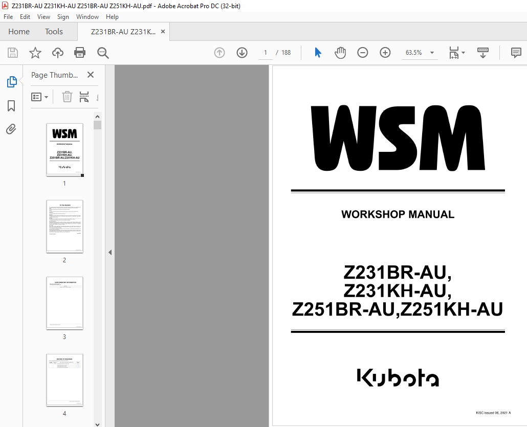
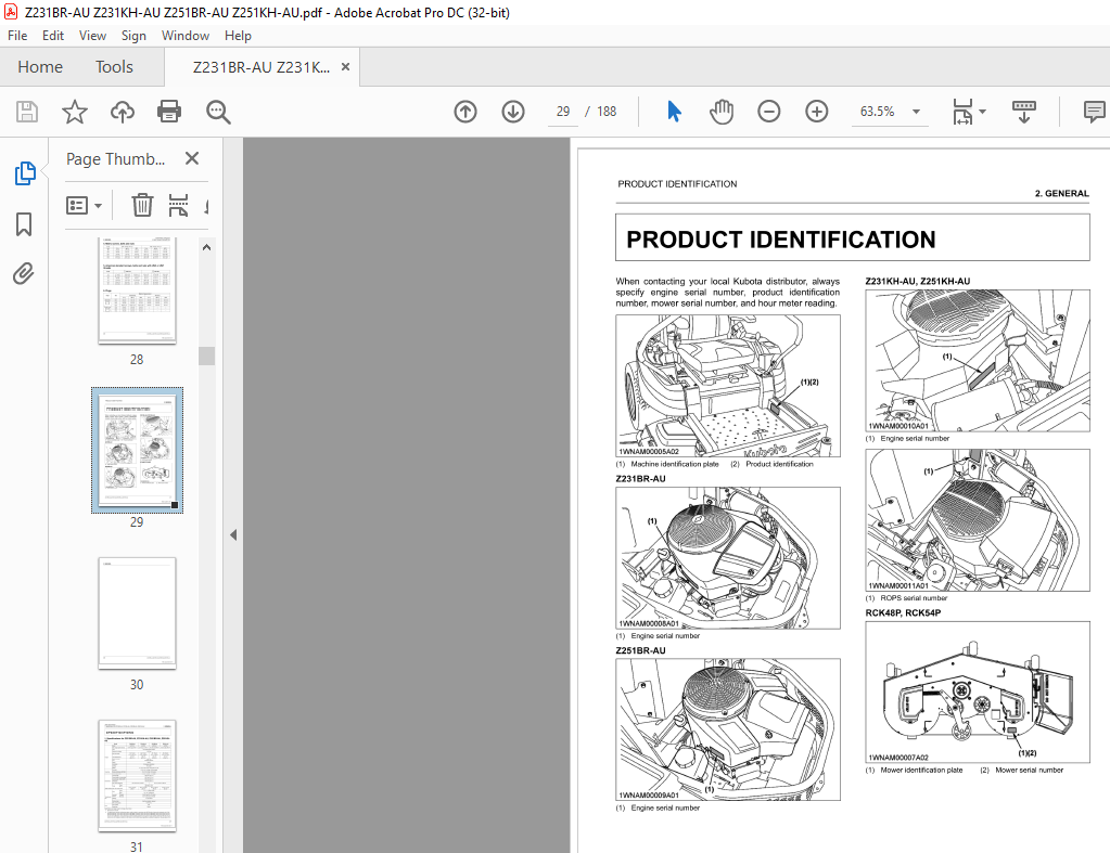
IMAGES PREVIEW OF THE MANUAL:

DESCRIPTION:
Kubota Zero Turn Mower Z231BR-AU Z231KH-AU 2251 BR-AU 2251 KH-AU Workshop Manual – PDF DOWNLOAD
TO THE READER
This workshop manual provides safety information for service activity, general information such as specifications and
dimensions of the machine, mechanisms and structure descriptions of the machine, and service procedures.
Safety
This section contains safety service descriptions and safety label information.
General
This section contains general instructions, tightening torques, general machine information and special tools.
Maintenance
This section contains information for the recommended oil and general maintenance procedures.
Each section basically consists of mechanism and servicing.
Mechanism
Mechanism part contains information and explanations for the structure, functions, and specifications of the machine
or component parts. This part should be comprehended before proceeding with troubleshooting, disassembling,
assembling, and servicing works.
Servicing
Servicing part contains information and procedures for maintenance, troubleshooting and repair works. The reader
should follow these instructions in order to satisfy any servicing work safely, correctly and quickly.
In this WSM, service specifications and service limits are defined as followings.
Service specifications:
Specification which corresponds to new machine’s ex-factory. It is based on quality standard, drawings, or actual
measurements conducted by Kubota. This value is used to determine whether there is a problem with the machine in
the event of a troubleshooting. However, it is necessary to consider degradation due to wear, based on the operating
time of the machine, application or maintenance condition.
Service limits:
Service limit is a value corresponding to the recommended performance limit by taking long term-use wear into
account. When the service limit is reached , the machine is required to have proper repair, overhaul or replacement in
order to keep safe and adequate performance.
All of the illustrations, photographs, specifications, and other information in this manual were created based on the
latest model at the time of publication.
The parts names used in this manual are unified into names representing the functions of the parts. Therefore, it does
not necessarily correspond to the names used in other materials (parts list, operators manual etc.) and the name on
the label/ identification plates on the product.
Kubota reserves the right to change all information at any time without notice.
TABLE OF CONTENTS:
Kubota Zero Turn Mower Z231BR-AU Z231KH-AU 2251 BR-AU 2251 KH-AU Workshop Manual – PDF DOWNLOAD
1 SAFETY
SAFETY FIRST 1-1
1 Working precautions 1-1
2 Preparing for emergencies 1-1
3 Working cautions 1-2
4 Starting machine safely 1-2
5 Preventing fires 1-3
6 Preventing acid burns 1-3
7 Avoiding high pressure fluid 1-3
8 Avoiding hot exhaust 1-4
SAFETY DECALS 1-5
1 Safety decals 1-5
2 Care of danger, warning and caution labels 1-10
2 GENERAL
GENERAL PRECAUTIONS 2-1
TIGHTENING TORQUES 2-3
1 General use screws, bolts, and nuts 2-3
2 Stud bolts 2-3
3 Hydraulic fittings 2-4
3 1 Hydraulic hose fittings 2-4
3 2 Hydraulic pipe cap nuts 2-4
3 3 Adapters, elbows, and others 2-5
4 Metric screws, bolts and nuts 2-6
5 American standard screws, bolts and nuts with UNC or UNF threads 2-6
6 Plugs 2-6
PRODUCT IDENTIFICATION 2-7
SPECIFICATIONS 2-9
1 Specifications for Z231BR-AU, Z231KH-AU, Z251BR-AU, Z251KH-AU 2-9
2 Specifications for RCK48P-124Z, RCK54P-127ZA 2-11
DIMENSIONS 2-13
HANDLING PRECAUTIONS FOR ELECTRICAL PARTS AND WIRING 2-15
1 Handling of wiring 2-15
2 Battery 2-16
3 Handling of fuse 2-17
4 Connector 2-17
5 Handling of circuit tester 2-18
6 Wiring colors 2-18
IMPLEMENT LIMITATIONS 2-19
SPECIAL TOOLS 2-21
1 Special tools for machine 2-21
1 1 Spanner wrench 2-21
3 MAINTENANCE
LUBRICANTS AND FUEL 3-1
SERVICE INTERVALS 3-3
CHECK AND MAINTENANCE 3-7
1 Daily check 3-7
1 1 Checking the engine oil level 3-8
1 2 Checking the amount of fuel and refueling 3-8
1 3 Checking and cleaning the air intake screen 3-9
1 4 Checking the tire pressure 3-10
1 4 1 Inflation pressure 3-10
1 5 Checking transaxle fluid level 3-10
1 6 Checking movable parts 3-10
Z231 BR-AU,Z231KH-AU,Z251 BR-AU,Z251 KH-AU iii
KiSC issued 06, 2021 A
2 Check points of every 25 hours 3-11
2 1 Cleaning precleaner element (except 2251 BR-AU) 3-11
2 2 Cleaning air cleaner element (2231 BR-AU, 2251 BR-AU) 3-12
3 Check points of every 50 hours 3-13
3 1 Checking engine start system 3-13
3 2 Checking OPC system 3-14
3 3 Changing engine oil (2231BR-AU, 2251BR-AU) 3-14
3 4 Replacing engine oil filter (2231 BR-AU, 2251 BR-AU) 3-15
3 5 Checking the muffler and spark arrester (if equipped) 3-16
4 Check points of every 100 hours 3-16
4 1 Changing engine oil (Z231KH-AU, Z251KH-AU) 3-16
4 2 Replacing precleaner element (except 2251 BR-AU) 3-17
4 3 Replacing air cleaner element (2231 BR-AU, 2251 BR-AU) 3-17
4 4 Replacing air cleaner element (2231KH-AU, 2251 KH-AU) 3-17
4 5 Cleaning engine shroud 3-18
4 6 Checking the spark plug 3-18
4 7 Checking the fuel filter 3-19
4 8 Checking the battery condition 3-20
4 8 1 Charging the battery 3-21
4 8 2 Storing the battery 3-22
4 9 Adjusting the throttle cable 3-22
4 1 O Replacing engine oil filter (2231 KH-AU, 2251 KH-AU) 3-23
5 Check points of every 400 hours 3-23
5 1 Replacing transaxle oil filter 3-23
5 2 Changing transaxle fluid 3-24
6 Check points of every 500 hours 3-25
6 1 Checking engine valve clearance (2231 KH-AU, 2251 KH-AU) 3-25
7 Check points of every 500 hours or every 1 year 3-25
7 1 Adjusting the electric clutch 3-25
8 Check points of after 500 hours 3-26
8 1 Cleaning combustion chamber 3-26
9 Check points of every 1 year 3-26
9 1 Replacing air cleaner element (2231 BR-AU, 2251 BR-AU) 3-26
9 2 Replacing air cleaner element (2231 KH-AU, 2251 KH-AU) 3-26
9 3 Changing engine oil (2231 BR-AU, 2251 BR-AU) 3-26
9 4 Replacing engine oil filter (2231 BR-AU, 2251 BR-AU) 3-26
9 5 Replacing fuel filter (2231 BR-AU, 2251 BR-AU) 3-26
9 6 Checking fuel lines 3-26
9 7 Checking muffler and spark arrester (if equipped) 3-26
9 8 Replacing spark plug 3-26
9 9 Checking hydraulic hose 3-26
9 10 Checking engine valve clearance (2231 BR-AU, 2251 BR-AU) 3-27
10 Check points of every 4 years 3-27
10 1 Replacing hydraulic hose 3-27
10 2 Replacing fuel line 3-27
11 Service as required 3-27
11 1 Replacing fuses 3-27
11 2 Checking and replacing blades 3-28
11 3 Replacing the mower belt 3-29
4 ENGINE
MECHANISM 4-1
1 Structure of engine 4-1
2 Fuel system 4-2
2 1 Structure of fuel system 4-2
3 Lubrication system 4-3
3 1 Structure of lubrication system 4-3
SERVICING 4-5
iv 2231 BR-AU ,2231 KH-AU ,2251 BR-AU ,2251 KH-AU
KiSC issued 06, 2021 A
1 Troubleshooting for engine 4-5
2 Servicing specifications for engine 4-9
3 Tightening torques for engine 4-10
4 Checking and adjusting ···· ·········· ···· ········· ···· ········ ·· ······· ·· ···· ··· ········ ····· ···· ····· ·· ··· ······· ··· ······ ···· ······ ······ ······ 4-11
5 Disassembling and assembling··· ······ ··········· ···· ···· ···· ····· ····· ····· ······ ····· ···· ····· ·· ··· ··· •··· ·· ······· ·· ···· ······· ········· 4-11
5 1 Separating engine 4-11
5 1 1 Removing battery 4-11
5 1 2 Removing tension spring 4-11
5 1 3 Removing electric clutch 4-11
5 1 4 Removing HST pulley 4-13
5 1 5 Removing rear upper frame 4-14
5 1 6 Disconnecting fuel hose 4-14
5 1 7 Disconnecting throttle cable 4-15
5 1 8 Disconnecting wire harness 4-15
5 1 9 Removing engine 4-16
5 1 10 Removing muffler 4-17
5 TRANSAXLE
MECHANISM 5-1
1 Function of transaxle 5-1
2 Hydraulic circuit of transaxle 5-1
3 Structure of transaxle 5-2
3 1 Transaxle external components 5-3
3 1 1 Function of transaxle external components 5-3
3 2 Transaxle internal components 5-3
3 2 1 Function of transaxle internal components 5-3
4 Transaxle specification 5-4
5 Parking brake 5-5
5 1 Outline of parking brake 5-5
SERVICING 5-7
1 Troubleshooting for transaxle 5-7
2 Servicing specifications for transaxle 5-9
3 Tightening torques for transaxle 5-10
4 Checking and adjusting 5-11
4 1 Motion control lever 5-11
4 1 1 Adjusting HST neutral 5-11
4 1 2 Adjusting maximum speed 5-12
4 1 3 Adjusting motion control lever alignment 5-12
5 Disassembling and assembling 5-13
5 1 Separating transaxle 5-13
5 1 1 Removing rear wheel 5-13
5 1 2 Loosening HST belt 5-13
5 1 3 Disconnecting rods 5-14
5 1 4 Disconnecting hydraulic hose 5-14
5 1 5 Separating transaxle 5-14
5 2 Disassembling transaxle 5-15
5 2 1 Removing hub 5-15
5 2 2 Removing filter and filter guard 5-16
5 2 3 Removing control arm assembly ····· ····· ····· ·· ··· ··· ······· ·· ········ ·· ········ ············ ········ ······ ········ ····· ···5-17
5 2 4 Removing fan and pulley 5-17
5 2 5 Removing brake arm assembly 5-18
5 2 6 Removing side cover 5-18
5 2 7 Removing bull, pinion, and reduction gears 5-19
5 2 8 Removing charge pump 5-20
5 2 9 Removing input shaft 5-21
5 2 10 Removing bypass arm 5-22
5 2 11 Removing swash plate 5-22
5 2 12 Removing center section 5-23
Z231 BR-AU Z231KH-AU,Z251 BR-AU Z251 KH-AU V
KiSC issued 06 2021 A
5 2 13 Removing cylinder blocks 5-24
5 2 14 Removing brake assembly 5-25
5 2 15 Removing axle shaft 5-25
5 3 Removing fuel tank 5-26
5 3 1 Removing mower 5-26
5 3 2 Removing battery 5-26
5 3 3 Removing seat 5-26
5 3 4 Removing R H fender ··· ······ ············ ··· ······ ······ ············ ···· ········ ··· ···· ····· ·· ··· ···· ·· ···· ····· ··· ··· ···· ··· ··· 5-26
5 3 5 Removing L H fender 5-27
5 3 6 Removing control lever panel 5-27
5 3 7 Removing fuel tank 5-28
5 4 Removing ROPS 5-29
5 4 1 Removing rear wheel 5-29
5 4 2 Removing ROPS 5-30
5 5 Removing motion control lever 5-30
5 5 1 Removing battery 5-30
5 5 2 Removing seat 5-30
5 5 3 Removing motion control lever 5-30
6 FRONT AXLE
MECHANISM 6-1
1 Structure of front axle 6-1
SERVICING 6-3
1 Troubleshooting for front axle 6-3
2 Tightening torques for front axle ···· ······ ··· ·············· ···· ······ ············ ···· ········ ··· ········· ·· ·· ··· ···· ···· ·· ········· ····· ······· 6-4
3 Disassembling and assembling ··· ·· ······ ············ ··· ······ ······ ············ ···· ········ ··· ········· ·· ·· ··· ···· ···· ·· ········· ····· ······· 6-5
3 1 Separating front wheel and wheel bracket 6-5
3 1 1 Removing front wheel 6-5
3 1 2 Removing wheel bracket 6-5
7 LIFT SYSTEM
MECHANISM 7-1
1 Structure of lift system 7-1
SERVICING 7-3
1 Troubleshooting for lift system 7-3
2 Tightening torques for lift system 7-4
3 Checking and adjusting 7-5
3 1 Checking link stopper 7-5
3 2 Adjusting link stopper 7-5
4 Disassembling and assembling 7-6
4 1 Removing link shafts 7-6
4 1 1 Removing mower 7-6
4 1 2 Removing link stopper 7-6
4 1 3 Removing cam ··· ··· ······· ·· ······ ··· ··· ········· ··················· ··· ····· ··· ····· ··· ··· ···· ···· ···· ····· ····· ····· ··· ······· ·· ······ 7-7
4 1 4 Removing link shafts 7-7
8 ELECTRICAL SYSTEM
MECHANISM ··· ···· ·· ·· ···· ·· ··· ······ ············ ······ ··· ······ ··· ····· ··· ······· ·············· ·············· ···· ···· ······· ·········· ··· ···· ···· ···· ···· ·· ····8-1
1 Wiring diagram 8-1
2 Starting system 8-2
2 1 Electrical circuit of starting system 8-2
2 1 1 Safety switch 8-3
2 1 2 Relays 8-5
3 Charging system·· ····· ·· ········ ···························· ··· ···· ···· ·· ·· ········ ··········· ············· ····· ······· ··············· ················ 8-6
3 1 Electrical circuit of charging system 8-6
3 2 Electrical circuit of gauge system 8-7
3 2 1 Hour meter 8-8
3 2 2 Head light 8-8
3 2 3 PTO clutch 8-8
vi Z231 BR-AU ,Z231 KH-AU ,Z251 BR-AU ,Z251 KH-AU
KiSC issued 06, 2021 A
3 2 4 PTO switch 8-8
SERVICING 8-9
1 Troubleshooting for electrical system 8-9
2 Servicing specifications for electrical system 8-12
3 Checking and adjusting 8-13
3 1 Battery 8-13
3 1 1 Checking battery voltage 8-13
3 1 2 Checking battery terminal connection 8-13
3 1 3 Checking battery specific gravity 8-13
3 2 Main switch 8-14
3 2 1 Checking connector voltage 8-14
3 2 2 Checking terminal continuity 8-14
3 3 Safety switches 8-15
3 3 1 Checking control of safety switches 8-15
3 3 2 How to find damaged switches (If the engine starts in combination 1 to 5) 8-16
3 3 3 Safety switch continuity test 8-17
3 3 4 Motion control lever switch 8-17
3 3 5 Checking parking brake switch harness 8-18
3 3 6 Checking parking brake switch continuity 8-18
3 3 7 Checking PTO switch harness 8-19
3 3 8 Checking PTO switch continuity 8-19
3 3 9 Checking seat switch harness 8-20
3 3 10 Checking seat switch continuity 8-20
3 4 Electric PTO clutch 8-20
3 4 1 Checking electric PTO clutch (Coil resistance) 8-20
3 4 2 Checking electric PTO clutch (Electromagnetic action) 8-20
3 4 3 Checking electric PTO clutch clearance 8-21
3 5 Relays 8-21
3 5 1 Checking relay 8-21
3 6 Hour meter 8-22
3 6 1 Checking hour meter harness 8-22
3 6 2 Checking hour meter terminal continuity 8-22
9 MOWER
MECHANISM 9-1
1 Structure of mower 9-1
2 Power transmission flow for mower 9-3
SERVICING 9-5
1 Troubleshooting for mower 9-5
2 Servicing specifications for mower 9-7
3 Tightening torques for mower 9-8
4 Checking and adjusting 9-9
4 1 Leveling mower deck 9-9
4 1 1 Adjusting anti-scalp rollers 9-9
4 1 2 Checking mower deck level (side-to-side) 9-9
4 1 3 Adjusting mower deck level (side-to-side) 9-10
4 1 4 Checking mower deck level (front-to-rear) 9-10
4 1 5 Adjusting mower deck level (front-to-rear) 9-11
5 Disassembling and assembling 9-12
5 1 Dismounting mower deck 9-12
5 1 1 Disconnecting mower belt 9-12
5 1 2 Disconnecting lift links 9-12
5 2 Mounting mower deck 9-12
5 2 1 Connecting lift link 9-12
5 2 2 Connecting mower belt 9-13
5 3 Disassembling mower deck 9-13
5 3 1 Removing tension pulley and mower belt 9-13
5 3 2 Removing tension arm and idler pulleys 9-13
Z231 BR-AU,Z231 KH-AU,Z251 BR-AU,Z251 KH-AU vii
KiSC issued 06, 2021 A
5 3 3 Removing blade 9-14
5 3 4 Removing blade shaft and pulley holder 9-15
5 3 5 Removing front plates 9-15
5 3 6 Removing anti-scalp rollers

