$37
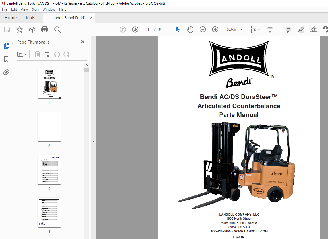
Landoll Bendi AC/DS DuraSteer™ Articulated Counterbalance Parts Manual – PDF DOWNLOAD
Landoll Bendi AC/DS DuraSteer™ Articulated Counterbalance Parts Manual – PDF DOWNLOAD
FILE DETAILS:
Landoll Bendi AC/DS DuraSteer™ Articulated Counterbalance Parts Manual – PDF DOWNLOAD
Language : English
Pages :184
Downloadable : Yes
File Type : PDF
TABLE OF CONTENTS:
Landoll Bendi AC/DS DuraSteer™ Articulated Counterbalance Parts Manual – PDF DOWNLOAD
Illustrated Parts List
Instructions for Ordering Parts 1-1
Brakes 1-2
Brake Caliper Assembly 1-2
Brake Installation – Prior to 07/16/2013 1-4
Brake Installation – After 07/17/2013 1-6
Brake Line Installation 1-8
Brake Pedal Assembly – After 01/28/2014 1-10
Brake Pedal Installation 1-14
Parking Brake Installation 1-16
Parking Brake Installation (B40HL Only) 1-18
Covers and Counterweights 1-20
Battery Door Installation 1-20
Counterweight Installation 1-22
Covers Installation 1-26
Covers Installation (B40HL Only) 1-32
Decals 1-36
Decal Kit – B30 1-36
Decal Placement 1-38
Electrical 1-40
Alarm and Lighting 1-40
Battery Connector Installation – B30 1-42
Battery Connector Installation – B40 1-44
Battery Guide Installation 1-45
Controller Panel Assembly 1-46
Controller Installation 1-48
Drive Motor Assembly, AC Shaft – B30 to S/N 08552 1-49
Drive Motor Assembly, AC Shaft – B30 from S/N 08553-08932 1-50
Drive Motor Assembly, AC Shaft – B30 from S/N 08935 – Current 1-51
Drive Motor Assembly, AC Shaft – B40, B40HL, & B40VNA to S/N 08403 1-52
Drive Motor Assembly, AC Shaft – B40, B40HL, & B40VNA from S/N 08409-08861 1-53
Drive Motor Assembly, AC Shaft – B40, B40HL, & B40VNA from S/N 08873 – Current 1-54
Fan Installation 1-55
Heavy Cable Diagram 1-56
Lift Pump Motor Assembly TO S/N 08212 (B30) & to S/N 08218 (B40) 1-58
Lift Pump Motor Assembly from S/N 08219 – 09000 (B30) & S/N 08222 – 08861 (B40) 1-59
Pump Motor Assembly 1-60
Light Wiring Diagram 1-62
Hydraulics 1-68
Control Hydraulics 1-68
Control Hydraulics (B40HL Only) 1-70
Hydraulic Connections, Frame 1-72
Hydraulic Control Valve Assembly 1-73
Hydraulic Diagram 1-74
Hydraulic Tank Components Installation 1-78
ii F-647-R2
TABLE OF CONTENTS INDEX
In-Tank Filter Assembly 1-80
Lift Pump and Motor Installation 1-82
Pressure Filter and Lines 1-84
Steering Column and Orbital Installation 1-85
Steering Control Valve Assembly 1-86
Tilt Cylinder 1-87
Tilt Cylinder, Limited Tilt 1-88
Front Rotation and Mast 1-90
Forks 1-90
Front Rotation Installation – Prior to 03/02/2016 1-92
Front Rotation Installation – After 03/03/2016 1-96
Front Rotation Installation (B40HL Only) 1-100
Front Rotation Installation (B40VNA Only) 1-104
Load Backrest 1-107
Load Wheel Assemblies 1-108
Mast Components Installation 1-110
Mast Components Installation (B40HL Only) 1-114
Mast Components Installation (B40VNA Only) 1-116
Wheel and Axle Installation 1-120
Operator Compartment 1-122
Accelerator Pedal Assembly – Prior to 07/22/2014 1-122
Accelerator Pedal Assembly – After 07/23/2014 1-123
Lift, Tilt, and Sideshift Controls 1-124
Lift, Tilt, and Sideshift Controls (B40HL Only) 1-126
Overhead Guard Installation 1-128
Seat Assembly Components 1-130
Seat Assembly 1-132
Seat Base Installation 1-136
Seat Base Installation (B40HL Only) 1-138
Steering Column Assembly 1-140
Steering Column and Dash Display Assembly 1-142
Powertrain 1-144
Drive Motor and Gearbox Installation 1-144
Drive Wheel Components 1-145
Gearbox Assembly, Brevini In-Line 1-146
Options 1-148
Accessories 1-148
Battery Restraint Assembly 1-150
Fast Charge Battery Assembly – B30 1-152
Fast Charge Battery Assembly – B40, B40HL & B40VNA 1-154
Fast Charge Battery Assembly, Field Installation – B30 1-156
Fast Charge Battery Assembly, Field Installation – B40 & B40VNA 1-158
Roll Out Battery Tray Assembly – B30 1-160
Roll Out Battery Tray Assembly – B40 1-162
Service Tools 1-164
Software Programs, Cables, Handsets and Documents 1-164
2 Glossary
3 Numerical Index
IMAGES PREVIEW OF THE MANUAL:

More products