$42
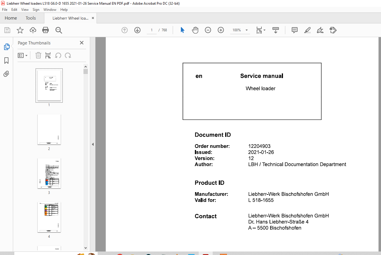
Liebherr Wheel loaders L 518-1655 Service manual – PDF DOWNLOAD
Liebherr Wheel loaders L 518-1655 Service manual – PDF DOWNLOAD
IMAGES PREVIEW OF THE MANUAL:
FILE DETAILS:
Liebherr Wheel loaders L 518-1655 Service manual – PDF DOWNLOAD
Language : English
Pages : 768
Downloadable : Yes
File Type : PDF
Size:114 MB
DESCRIPTION:
Liebherr Wheel loaders L 518-1655 Service manual – PDF DOWNLOAD
PrefaceNotes for users
- This service manual is designed for trained specialist staff of the Liebherr organisation and their dealers.
- This service manual contains specialist knowledge for repairing Liebherr construc- tion machines. Basic specialist knowledge on electronics, hydraulics, mechanics and engine technology is not contained in this service manual. Therefore special- ized training and qualifications are necessary. Liebherr recommends participating in the Liebherr training program for construction machines.
In this service manual you will find information on:
— Special tools— Technical data— Maintenance intervals and maintenance tasks— Adjustment procedures— Structure and function descriptions— Removal and installation tasks— Circuit diagrams, hydraulic plans and technical drawings
- You will find information on controls and operation in the operator’s manual. Information on spare parts are in the spare parts catalogue. Please observe the local accident prevention laws.
- You can find information on repairs of machine parts in the service documentation under “Wheel loader – repair instructions”.
Introduction:
Intended Use:1.1. Laws, Rules, Guidelines and Safety Regulations
To ensure safe operation:
- Consult with the worksite manager about safety regulations at the place of use.
- Adhere to safety regulations at the place of use.
- Follow traffic regulations.
- Adhere to valid guidelines provided by insurers (for example, employers’ professional liability insurance companies, accident insurance, etc.).
- Avoid working methods that can endanger safety.
- Follow all intervals specified for recurrent checks and inspections as outlined in this operator’s manual.
1.2. Intended Use of Wheel Loader
The wheel loader is used to pick up, move, and dump the following materials:
- Soil
- Stones
- Broken rocks
- Bulk materials
This applies to a standard machine under normal operating conditions. Special applications are described in a separate options operator’s manual.
To ensure the intended use:
- Adhere to the operator’s manual.
- Follow maintenance intervals.
- Carry out inspection and maintenance tasks.
- Follow the specifications in the technical data.
- When using the machine on public roads, ensure it complies with applicable national regulations.
- Only lift loads with intended working attachments (fork prongs, crane boom), which must be properly fitted and functioning.
- Ensure that machines used underground (for mining and tunnel construction) are fitted with systems to reduce exhaust emissions (such as diesel particulate filters).
- Adhere to the requirements of each individual country for underground operation.
- For special uses, use special working attachments and, if necessary, special safety equipment.
- Exclusively mount and use special working attachments with approval and as per the stipulations of the manufacturer of the basic machine.
TABLE OF CONTENTS:
Liebherr Wheel loaders L 518-1655 Service manual – PDF DOWNLOAD
010 Introduction 010-1
010.1 Safety instructions 010-4
010.1.1 Information on these instructions 010-4
010.1.1.1 Representation of warning messages 010-4
010.1.1.2 Graphic symbols in these instructions 010-4
010.1.2 Intended use 010-5
010.1.2.1 Laws, rules, guidelines and safety regulations 010-5
010.1.2.2 Intended use 010-5
010.1.2.3 Foreseeable misuse 010-6
010.1.2.4 Operating conditions 010-6
010.1.2.5 Disposal 010-7
010.1.3 Description of staff 010-7
010.1.3.1 Personal protective equipment 010-7
010.1.3.2 Requirements for staff 010-8
010.1.3.3 Operating company 010-8
010.1.3.4 Operator 010-9
010.1.3.5 Maintenance staff 010-9
010.1.3.6 Refrigeration technician 010-10
010.1.3.7 Slinger 010-11
010.1.3.8 Spotter 010-12
010.1.4 Protective devices on the machine 010-12
010.1.6 Safe operation 010-14
010.1.6.1 Intoxicants 010-14
copylight © Liebherr-Werk Bischofshofen GmbH 2021
L518-1655 IIIBHIRR 5
Contents Service manual
010.1.6.2 Dangerous fuels and operating fluids 010-14
010.1.6.3 Transporting machine 010-15
010.1.6.4 Access to machine 010-15
010.1.6.5 Machine danger zone 010-16
010.1.6.6 Visibility 010-16
010.1.6.7 Protection against vibration 010-17
010.1.6.8 Operation of machine 010-18
010.1.7 Safe maintenance 010-21
010.1.7.1 Spare parts 010-21
010.1.7.2 Heavy parts 010-21
010.1.7.3 Regular checks 010-22
010.1.8 Modifications to the machine 010-22
010.1.8.1 Modifications, add-ons and retrofittings 010-22
010.2 Special tools for maintenance and repair work 010-23
010.2.1 Special tools, general 010-23
010.2.2 Special tools for the engine 010-25
010.2.3 Special tools for lift cylinders 010-29
010.2.4 Special tools for lift cylinders 010-30
010.2.5 Special tools for tilt cylinders 010-30
010.2.6 Special tools for tilt cylinders 010-31
010.2.7 Special tools for quick coupler locking hydraulic cylinder 010-32
010.2.8 Special tools for steering wheel 010-32
010.2.9 Special tools for steering cylinders 010-32
010.2.10 Special tools for steering cylinders 010-33
010.2.11 Special tools for the electrical system 010-33
010.2.12 Special tools for front axle 010-35
010.2.13 Special tools for rear axle 010-35 C: …!.l
010.2.14 Special tools for air conditioning system 010-36
010.3.2 Liebherr standards for assembly instructions and tightening torqueso10-46
010.4 Preservation guidelines
010.4.1 General information
010.4.2 Machine out of service for an unknown period of time
010.4.3 Putting the machine out of service
Out of service for up to 2 months
Out of service for up to 12 months
Out of service for longer than 12 months
010.4.4 Putting back into service
After being out of service for 2 months
After being out of service for 12 months
010.4.4.3 After being out of service for longer than 12 months 010-51
Technical data 020-1
020.1 Overall machine 020-5
020.1.1 Complete machine with bucket (z-bar kinematics)
L518-1655; 020-5
020.1.2 Working attachment: light material bucket
L518-1655; 020-6
020.1.3 Working attachment: high dump bucket
L518-1655; 020-7
020.1.4 Working attachment: forklift
L518-1655; 020-9
020.2 Drive group 020-11
020.2.1 Diesel engine
L518-1655; 020-11
020.2.2 Fuel tank
L518-1655; 020-12
020.2.2.1 Plastic version 020-12
020.2.2.2 Diesel exhaust fluid tank 020-12
020.2.3 Fuel level sensor
L518-1655; 020-12
020.2.4 Fuel pre-filter
L518-1655; 020-13
020.2.5 Fuel fine filter
L518-1655; 020-13
copylight © Liebherr-Werk Bischofshofen GmbH 2021
IIIBHIRR 7
Contents Service manual
020.2.6 Clutch
L518-1655; 020-13
020.3 Cooling system 020-14
020.3.1 Fan pump
L518-1655; 020-14
020.3.2 Fan motor
L518-1655; 020-14
020.3.3 Hydraulic oil temperature sensor B8
L518-1655; 020-14
020.4 Working hydraulics 020-15
020.4.1 Working pump
L518-1655; 020-15
020.4.2 Control block
L518-1655; 020-15
020.4.3 Pilot control unit
L518-1655; 020-15
020.4.4 Pilot control hydro accumulator
L518-1655; 020-16
020.4.5 Stabilisation module
L518-1655; 020-16
020.4.6 Ride control hydro accumulator
L518-1655; 020-16
020.4.7 Lift cylinder
L518-1655/0-59975; 020-16
020.4.8 Lift cylinder
L518-1655/59976-; 020-17
020.4.9 Tilt cylinder
L518-1655/0-60128; 020-17
020.4.10 Tilt cylinder
L518-1655/60129-; 020-17
020.5 Travel hydraulics 020-18
020.5.1 Travel pump
020.6 Hydraulic components 020-20 ~
iii
020.6.1 Return suction filter 0 “…’ 0
L518-1655/0-57748; 020-20 “‘ ~ ID
020.6.2 Return suction filter …J
L518-1655/57749-; 020-20
020.6.3 Breather filter with filler strainer
Service manual Contents
L518-1655
020.7 Steering system
020.7.1 Servostat
L518-1655;
020.7.2 Steering cylinder
L518-1655/0-59997;
020.7.3 Steering cylinder
L518-1655/59998-;
020.8 Brake system
020.8.1 Drum brake
L518-1655;
020.8.2 Inch/brake unit
L518-1655;
020.8.3 Brake light pressure switch B12
L518-1655;
020.8.4 Spring accumulator cylinder for parking brake
L518-1655;
020.9 Electrical system
020.9.1 Central control unit (Master 4)
L518-1655/0-60066;
020.9.2 Central control unit (Master5-Mini)
L518-1655/60067-;
020.9.3 Compact module
L518-1655;
020.9.4 BatteryL518-1655;
020.9.5 Voltage transformerL518-1655;
020.9.6 Reversing cameraL518-1655;
020.10 Gearbox
020.10.1 TransmissionL518-1655;
020.10.2 Output B101 speed sensorL518-1655;
020.11 Axles and drive shafts
020.11.1 Front axle
020.11.2 Front axle with engageable differential lockout (option)
020.11.3 Rear axle
020.11.4 Rear axle when front axle has engageable differential lockout
copylight © Liebherr-Werk Bischofshofen GmbH 2021
IIIBHIRR 9
Contents Service manual
020.11.5 Drive shaft
L518-1655; 020-28
020.11.6 Tyres
L518-1655; 020-28
020.11.6.2 Tyres for timber work 020-29
020.11.6.3 Special tyres 020-30
020.12 Working attachment 020-31
020.12.1 Quick coupler locking hydraulic cylinder
L518-1655; 020-31
020.13 Operator’s cab, heating and air conditioning 020-32
020.13.1 Dryer
L518-1655; 020-32
020.13.2 Pressure switches
L518-1655; 020-32
020.14 Lubrication system 020-33
020.14.1 Central lubrication pump EP1
L518-1655; 020-33
020.14.2 Progressive distributor
L518-1655; 020-33
020.14.2.1 MX-F 020-33
020.14.2.2 MX-F 25 020-33
020.14.2.3 MX-F 45 020-33
020.14.2.4 MX-F 75 020-34
020.14.2.5 MX-F105 020-34
030 Maintenance 030-1
030.1 Maintenance and inspection schedule 030-10
030.2 Filling quantities and lubrication chart 030-15
030.2.1 Recommended lubricants
L518-1655; 030-15
030.3.1.2 Safety data sheets 030-16 0 “‘ ~
030.3.1.3 Technical data sheets 030-16 ID
030.3.1.4 Specific Liebherr standards 030-16
030.3.2 General information on changing lubricants and fuels 030-16
copylight © Liebheir-Werk Bischofshofen GmbH 2021
10 IIIBHIRR L518-1655
Service manual Contents
030.3.3 Converting hydraulic system from mineral oils to biodegradable
hydraulic fluids 030-17
030.3.4 Diesel fuels
L518-1655/0-57748; 030-17
030.3.4.1 Minimum quality requirement 030-17
030.3.4.2 Operating temperatures of diesel fuels 030-17
030.3.4.3 Minimum quality requirement 030-18
030.3.5 Diesel fuels
L518-1655/57749-; 030-18
030.3.5.1 Minimum quality requirement 030-18
030.3.5.2 Operating temperatures of diesel fuels 030-18
030.3.5.3 Minimum quality requirement 030-18
030.3.6 Diesel exhaust fluid
L518-1655; 030-19
030.3.6.1 Liebherr recommendation 030-19
030.3.6.2 Minimum quality requirement 030-19
030.3.7 Engine oils
L518-1655; 030-19
030.3.7.1 Liebherr recommendation 030-19
030.3.7.3 Minimum quality requirement 030-19
030.3.8 Refrigerant
L518-1655; 030-20
030.3.9 Coolant
L518-1655; 030-20
030.3.9.1 Requirements for the water used 030-20
030.3.9.2 Antifreeze and corrosion inhibitor 030-20
030.3.9.3 Minimum quality requirement 030-21
030.3.10 Hydraulic oil
L518-1655; 030-21
030.3.10.1 Liebherr recommendation 030-21
C: …!.l 030.3.10.2 Minimum quality requirement 030-21 :;;:
0 ;;;, 030.3.10.3 Oil analysis 030-22
“0′
;;; 030.3.10.4 Oil change 030-22 0
~
~ 030.3.11 Transmission
i0′ i L518-1655; 030-22 “…’ 0 “~’ 030.3.11.1 Liebherr recommendation 030-22 ID
Contents Service manual
030.3.12.1 Liebherr recommendation 030-23
030.3.12.2 Minimum quality requirement 030-23
030.3.13 Brake oil
L518-1655; 030-23
030.3.13.1 Liebherr recommendation 030-23
030.3.14 Lubrication grease
L518-1655; 030-24
030.3.14.1 Liebherr recommendation 030-24
030.3.14.2 Minimum quality requirement 030-24
030.3.15 Windscreen washer fluid
L518-1655; 030-24
030.3.15.1 Liebherr recommendation 030-24
030.3.15.2 Minimum quality requirement 030-24
030.3.16 Refrigerant oil for air conditioning compressor
030.3.16.1 Liebherr recommendation 030-24
030.4 Maintenance tasks 030-25
030.4.1 Safety precautions
L518-1655; 030-25
030.4.2 Preparatory tasks for maintenance 030-25
030.4.2.1 Maintenance positions
L518-1655; 030-26
030.4.2.2 Service hatches
L518-1655; 030-27
030.4.2.3 Turning off the battery main switch
L518-1655; 030-29
030.4.3 Overall machine 030-30
030.4.3.1 Checking the machine is in the proper condition
L518-1655; 030-30
030.4.3.2 Removing loose parts, dirt, ice and snow from
machine
030.4.4.1 Checking diesel engine oil level
L518-1655; 030-44
copylight © Liebheir-Werk Bischofshofen GmbH 2021
12 IIIBHIRR L518-1655
Service manual Contents
030.4.4.2 Changing the engine oil
L518-1655; 030-45
030.4.4.3 Changing the diesel engine oil filter
L518-1655; 030-47
030.4.4.4 Diesel engine: checking V-ribbed belt
L518-1655; 030-48
030.4.4.5 Changing the V-ribbed belt on the diesel engine
L518-1655; 030-50
030.4.4.6 Checking diesel engine valve clearance
L518-1655; 030-51
030.4.4.7 Diesel engine: changing the oil separator filter
cartridge
L518-1655; 030-54
030.4.4.8 Diesel engine: Checking the crankcase bleeder
system
L518-1655; 030-54
030.4.4.9 Diesel engine: Checking the glow plugs
L518-1655; 030-55
030.4.4.10 Draining condensate and sediment from the fuel tank
L518-1655; 030-56
030.4.4.11 Draining off condensate from the fuel pre-filter
L518-1655; 030-57
030.4.4.12 Changing the fuel pre-filter element
L518-1655; 030-58
030.4.4.13 Changing the fuel fine filter element
L518-1655; 030-60
030.4.4.14 Bleeding the fuel system
L518-1655; 030-61
030.4.4.15 Exhaust system: changing filter cartridge of diesel
exhaust fluid pump
L518-1655; 030-62
030.4.4.16 Exhaust system: changing filter cartridge of diesel
exhaust fluid pre-filter
system is in good condition and not loose or leaking
L518-1655; 030-70
030.4.4.21 Cleaning or changing the diesel particulate filter
L518-1655; 030-73
copylight © Liebherr-Werk Bischofshofen GmbH 2021
L518-1655 IIIBHIRR 13
Contents Service manual
030.4.5 Cooling system 030-76
030.4.5.1 Checking the coolant level in the cooling system
L518-1655; 030-76
030.4.5.2 Coolant: checking anti-freeze and corrosion protection
agent concentration
L518-1655; 030-78
030.4.5.3 Cleaning the cooling system
L518-1655; 030-86
030.4.5.4 Changing coolant in cooling system
L518-1655; 030-87
030.4.6 Working hydraulics 030-89
030.4.6.1 Cleaning and lubricating the pilot control unit
L518-1655; 030-89
030.4.7 Hydraulic components 030-90
030.4.7.1 Checking oil level in hydraulic tank
L518-1655; 030-90
030.4.7.2 Draining off condensate and sediment from the
hydraulic tank
L518-1655; 030-92
030.4.7.3 Changing the hydraulic tank return suction filter
cartridge
L518-1655/0-577 48; 030-93
030.4.7.4 Hydraulic tank: changing filter cartridge in returnsuction
filter
L518-1655157749-; 030-94
030.4.7.5 Changing the hydraulic tank breather filter
L518-1655; 030-95
030.4.7.6 Hydraulic tank: changing oil
L518-1655; 030-96
030.4.8 Steering system 030-98
030.4.8.1 Test steering
L518-1655; 030-98
030.4.8.2 Steering cylinder: lubricating bearing
L518-1655; 030-98 C: .!l
030.4.9.4 Checking gap and wear on service brake linings
L518-1655; 030-103
030.4.10 Electrical system 030-107
copylight © Liebheir-Werk Bischofshofen GmbH 2021
14 IIIBHIRR L518-1655
Service manual Contents
030.4.10.1 Checking function of the lighting and horn
L518-1655; 030-107
030.4.10.2 Checking the battery fluid levels and terminals
L518-1655; 030-108
030.4.10.3 Use the control lever to change the travel direction
switch rocker and cap.
L518-1655; 030-110
030.4.11 Gearbox 030-112
030.4.11.1 Transmission: checking oil level
L518-1655; 030-112
030.4.11.2 Changing transmission oil
L518-1655; 030-113
030.4.12 Axles and drive shafts 030-115
030.4.12.1 Checking axle oil levels
L518-1655; 030-115
030.4.12.2 Changing axle oil
L518-1655; 030-117
030.4.12.3 Lubricating rear axle kingpin bearings
L518-1655; 030-120
030.4.12.4 Checking the fitting of the rear axle kingpin bearings
and steering rod taper connections
L518-1655; 030-120
030.4.12.5 Checking the tightening torque of the front axle
fastening bolts
L518-1655; 030-121
030.4.12.6 Checking the drive shaft
L518-1655; 030-122
030.4.12.7 Tyres: checking tyre pressure
L518-1655; 030-123
030.4.12.8 Checking the wheel tightness
L518-1655; 030-124
030.4.13 Steel parts of the basic machine 030-124
030.4.13.1 Lubricating the articulated bearing and rear oscil-
C:
lating bearing
…!.l L518-1655; 030-124 :;;:
0 ;;;, 030.4.13.2 Lubricating the articulation stops
“‘ L518-1655; 030-125 0
;;;
0 ~ 030.4.13.3 Cooler hood: lubricating moving parts with pene-
~ trating oil
i’i L518-1655; 030-126 0 “…’ 0 “‘ 030.4.13.4 Engine bonnet: lubricating moving parts with pene- ~ ID trating oil
…J L518-1655; 030-126
030.4.13.5 Service hatches: cleaning and maintaining seals
L518-1655; 030-127
copylight © Liebherr-Werk Bischofshofen GmbH 2021
L518-1655 IIIBHIRR 15
Contents Service manual
030.4.14 Working attachment 030-128
030.4.14.1 Lubricating the lift arms and working attachment
L518-1655; 030-128
030.4.14.2 Checking the lift arm bucket bearing bushings
L518-1655; 030-129
030.4.14.3 Checking lift arm bucket stops
L518-1655; 030-129
030.4.14.4 Lubricating and testing bearings on quick coupler
L518-1655; 030-130
030.4.15 Operator’s cab, heating and air conditioning 030-131
030.4.15.1 Cleaning operator’s cab air filter
L518-1655; 030-131
030.4.15.2 Changing the cab air filter
L518-1655; 030-132
030.4.15.3 Safety belt: checking condition and function
L518-1655; 030-133
030.4.15.4 Windscreen washer system: testing
L518-1655; 030-134
030.4.15.5 Windscreen washer system: filling windscreen
washer fluid
L518-1655; 030-134
030.4.15.6 Operator’s cab: lubricating locking mechanism and
cylinder with penetrating oil
L518-1655; 030-135
030.4.15.7 Operator’s cab: cleaning and maintaining seals
L518-1655; 030-135
030.4.15.8 Checking the indicator bead in the air conditioning
dryer-collector unit
L518-1655; 030-136
030.4.15.9 Heating and air conditioning unit: Testing function
L518-1655; 030-137
030.4.16 Lubrication system 030-138
030.4.16.1 Central lubrication system: checking level in grease
reservoir
C: L518-1655; 030-138 …!.l :;;:
030.4.16.2 Central lubrication system: checking pipes, hoses 0 ;;;,
and lubrication points for leaks and damage. “0′
L518-1655; 030-139 ;;;
0
~
030.4.16.3 Central lubrication system: checking lubrication of ~
bearings iii 0
L518-1655; 030-140 “…’ 0 “‘
030.5 Testing and adjustment checklist ~ ID
L518-1655; 030-141 …J
030.6 Testing and adjustment tasks 030-145
030.6.2.1 Preparing for adjustment procedures
L518-1655; 030-145
030.6.2.2 Hydraulic oil and coolant: operating temperature
L518-1655; 030-147
030.6.2.3 Service management
L518-1655; 030-148
Drive group 030-149
030.6.3.1 Pedals: calibration
L518-1655; 030-149
030.6.3.2 Diesel engine speed
L518-1655; 030-150
030.6.3.3 Reading the diesel engine service files
L518-1655; 030-150
Cooling system 030-153
030.6.4.1 Fan motor: fan speed proportional solenoid
L518-1655; 030-153
Working hydraulics 030-155
030.6.5.1 Control valve block: secondary pressure relief valves
L518-1655; 030-155
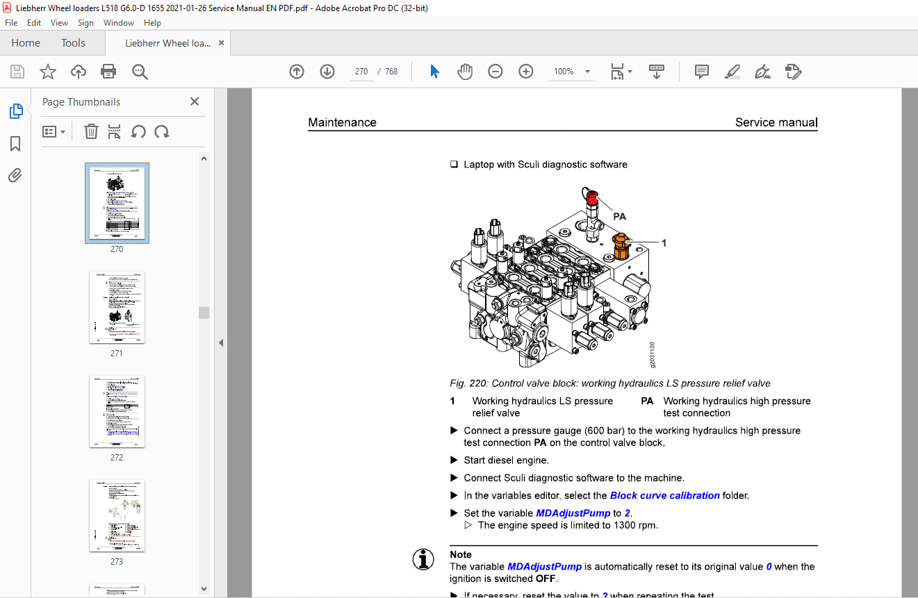
030.6.5.2 Control valve block: working hydraulics LS pressure
relief valve
L518-1655; 030-157
030.6.5.3 Stabilisation module (option), safety valve
L518-1655; 030-159
030.6.5.4 Ride control hydro accumulator (option): nitrogen
filling
L518-1655; 030-161
Hydraulic components 030-163
030.6.6.1 Checking the hydraulic lines for damage
L518-1655; 030-163
Travel hydraulics 030-168
030.6.7.1 Travel pump high pressure sensor B102: Deviation
Contents Service manual
030.6.7.6 Travel pump: automatic block curve calibration (from
software version (Master4) 020 or from serial number
60030)
L518-1655; 030-178
030.6.7.7 Travel motor: manual calibration (maximum swivel
angle)
L518-1655; 030-178
030.6.8 Brake system 030-181
030.6.8.1 Inching brake pedal: basic setting
L518-1655; 030-181
030.6.8.2 Angle sensor for inching function: checking basic
setting
L518-1655; 030-182
030.6.9 Electrical system 030-183
030.6.9.1 Central control unit (Master4) Creating a Servicefile
L518-1655/0-600066; 030-183
030.6.9.2 Central control unit (Master5): creating service file
L518-1655/600067-; 030-187
030.6.9.3 Updating the central controller software
L518-1655/0-60066; 030-188
030.6.9.4 Central control unit (Master5): software update
L518-1655/60067-; 030-190
030.6.9.5 Setting the IP addresses of the central control unit
(Master4)
L518-1655; 030-194
030.6.9.6 Resetting the central control unit (Master4)
L518-1655/0-60066; 030-196
030.6.9.7 Central control unit (Master5): resetting to factory
settings
L518-1655/60067-; 030-198
030.6.9.8 Central control unit (Master5): connecting Sculi diagnostic
software
L518-1655/60067-; 030-199
030.6.9.9 Central control unit (Master5): connecting LiFT function
L518-1655/60067-; 030-203 C: …!.l
Service manual Contents
030.6.12 Options 030-209
030.6.12.1 LiDAT: connecting to LiDAT module
L518-1655; 030-209
030.6.12.2 LiDAT: software update for LiDAT module
L518-1655; 030-211
030.6.12.3 LiDAT: creating report and snapshot
L518-1655; 030-213
040 Drive group 040-1
040.1 Engine 040-2
040.1.1 Diesel engine overview
L518-1655; 040-2
040.1.2 Electrical components of the diesel engine
L518-1655; 040-6
040.1.3 Fuel system 040-16
040.1.3.1 Overview of the fuel system
L518-1655; 040-16
040.1.3.2 Fuel level sensor
L518-1655; 040-17
040.1.3.3 Fuel pre-filter
L518-1655; 040-19
040.1.3.4 Fuel fine filter
L518-1655; 040-20
040.1.4 Air filter system 040-21
040.1.4.1 Air filter
L518-1655; 040-21
040.1.5 Exhaust system 040-21
040.1.5.1 Overview of exhaust system
L518-1655; 040-22
040.1.5.2 Diesel particulate filter (DPF): overview
L518-1655; 040-24
040.1.5.3 SCR system
.C!l: L518-1655; 040-28 … :;;: 040.1.5.4 Sampling module 0 ;;;,
“‘ L518-1655; 040-32 0
;;; 0 040.1.5.5 Diesel exhaust fluid pre-filter
~
~ L518-1655/57749-; 040-33
i0′ i 040.2 Clutch “…’ 0 L518-1655; 040-34 “‘ ~ ID
…J
050 Cooling system 050-1
050.1 Overview of cooling system
L518-1655; 050-2
copylight © Liebherr-Werk Bischofshofen GmbH 2021
L518-1655 IIIBHIRR 19
Contents Service manual
050.2 Cooling system hydraulics 050-4
050.2.1 Overview of cooling system hydraulics
L518-1655/0-577 48; 050-4
050.2.2 Overview of cooling system hydraulics
L518-1655157749-; 050-7
050.2.3 Fan pump
L518-1655; 050-10
050.2.4 Fan motor
L518-1655; 050-11
050.3 Cooling system electronics 050-13
050.3.1 General overview of electronic control system
L518-1655; 050-13
050.3.2 Temperature sensor for coolant
L518-1655; 050-16
050.3.3 Hydraulic oil temperature sensor
L518-1655; 050-17
050.3.4 Temperature sensor for charge air
L518-1655; 050-18
050.4 Cooler 050-20
050.4.1 Cooler unit
L518-1655; 050-20
050.5 Reversible fan drive 050-21
050.5.1 Overview of reversible fan drive
L518-1655/0-57748; 050-21
050.5.2 Overview of reversible fan drive
L518-1655/57749-; 050-24
050.5.3 Fan reversal valve block
L518-1655; 050-28
060 Working hydraulics 060-1
060.1 Overview of working hydraulics
L518-1655/0-57748; 060-2
060.2 Overview of working hydraulics C: .!l
L518-1655/57749-; 060-8 … :;;:
L518-1655; 060-27
060.5.2 Pilot control unit
L518-1655; 060-31
copylight © Liebheir-Werk Bischofshofen GmbH 2021
20 IIIBHIRR L518-1655
Service manual
L518-1655
060.5.3 Pilot pressure for solenoid valve
L518-1655;
060.6 Ride control
060.6.1 Overview of ride control system
L518-1655;
060.6.2 Stabilisation module
L518-1655;
060. 7 Pipe break protection
060.7.1 Pipe break protection: overview
L518-1655;
060.7.2 Valve block for pipe break protection
L518-1655;
060.7.3 Solenoid valve for release of the ride control
L518-1655;
070 Travel hydraulics
070.1 Overview of travel hydraulics
L518-1655/0-577 48;
070.2 Overview of travel hydraulics
L518-1655157749-;
070.3 Travel pump
L518-1655;
070.4 Travel motors
070.4.1 Travel motor
L518-1655;
080 Hydraulic components
080.1 Hydraulic system: overview
L518-1655/0-57748;
080.2 Hydraulic system: overview
L518-1655157749-;
080.3 Hydraulic tank
080.3.1 Overview of hydraulic tank
L518-1655/0-57748;
080.3.2 Overview of hydraulic tank
L518-1655/57749-;
080.3.3 Return-suction filter
L518-1655/0-57748;
080.3.4 Return suction filter
L518-1655/57749-;
080.3.5 Breather filter
Contents Service manual
090 Steering system 090-1
090.1 Steering system overview
L518-1655/0-57748; 090-2
090.2 Steering system overview
L518-1655/57749-; 090-6
090.3 Servostat
L518-1655; 090-10
100 Brake system 100-1
100.1 Overview of brake system
L518-1655/0-57748; 100-2
100.2 Overview of brake system
L518-1655/57749-; 100-6
100.3 Service brake and parking brake 100-10
100.3.1 Drum brake
L518-1655; 100-10
100.4 Service brake 100-15
100.4.1 Inch/brake unit
L518-1655; 100-15
100.4.2 Inching function angle sensor
L518-1655; 100-16
100.4.3 Brake light pressure switch
L518-1655; 100-18
100.5 Parking brake 100-20
100.5.1 Parking brake solenoid valve
L518-1655; 100-20
100.5.2 Spring accumulator cylinder for parking brake
L518-1655; 100-21
110 Electrical system 110-1
110.1 Overview of electrical system
110.4.1 General overview of the electronic control system 0 “…’ 0
L518-1655/0-60066; 110-11 “‘ ~ ID
110.4.2 General overview of electronic control system …J
L518-1655/60067-; 110-13
110.4.3 Central control unit (Master4)
L518-1655/0-60066; 110-14
copylight © Liebheir-Werk Bischofshofen GmbH 2021
22 IIIBHIRR L518-1655
Service manual
L518-1655
110.4.4 Central control unit (Master5 Mini)
L518-1655/60067-;
110.4.5 Modules
110.4.5.1
110.4.5.2
Overview of compact module
L518-1655;
Compact module
L518-1655;
110.5 Electrical components of the driver’s cab
110.5.1 Overview of electrical components in the operator’s cab
L518-1655;
110.5.2 Fuse boards
110.5.3 Door contact switch
110.6 Electrical components in the rear section
110.6.1 Battery installation
110. 7 Rear area monitoring with camera
110.7.1 Overview of rear area monitoring with camera
110.7.2 Camera
120 Gearbox
120.1 Overview of the transmission
120.2 Transmission electronics
120.2.1 Output speed sensor
L518-1655;
130 Axles and drive shafts
130.1 Axles
Overview of engageable differential lockout
Overview of engageable differential lockout
130.1.3.3 Valve block for parking brake and differential lockout
130.2 Cardan shafts
130.2.1 Drive shaft
140 Steel parts of the basic machine
140.1 Vehicle frame
140.1.1 Articulation bearing
140.1.2 Articulation lock
150 Working attachment
150.1 Lift arms for Z kinematics
150.1.1 Lift arms for Z kinematics
150.2 Quick coupler
150.2.1 Quick coupler
150.2.2 Quick coupler hydraulics
Overview of quick coupler hydraulics
L518-1655/0-51094
Overview of quick coupler hydraulics
Valve block for quick coupler
L518-1655;160 Operator’s cab, heating and air conditioning
160.1 Overview of the operator’s cab, heating and air conditioning unit
160.2 Display and control elements
160.2.1 Display
160.2.2 Control lever
160.2.3 Accelerator pedal
160.3 Heating, ventilation, air conditioning
160.3.1 Overview of heating, ventilation and air conditioning system
160.3.2 Heating and air conditioning unit
Service manual Contents
160.3.2.1 Heating and air conditioning unit
L518-1655; 160-14
160.3.2.2 Blower
L518-1655; 160-16
160.4 Air conditioning 160-17
160.4.1 Air conditioning (optional)
L518-1655; 160-17
160.4.2 Air conditioning compressor
L518-1655; 160-18
160.4.3 Condenser
L518-1655; 160-20
160.4.4 Dryer-collector unit
L518-1655; 160-20
160.4.5 Air conditioning pressure switch
L518-1655; 160-22
170 Lubrication system 170-1
170.1 Liebherr automatic central lubrication system 170-2
170.1.1 Automatic central lubrication system: overview
L518-1655; 170-2
170.1.2 Central lubrication pump EP-1
L518-1655; 170-6
170.1.3 Progressive distributor MX-F
L518-1655; 170-9
190 Options 190-1
190.1 LiDAT 190-2
190.1.1 Overview of LiDAT
L518-1655; 190-2
190.1.2 LiDAT on machine
L518-1655/0-50943; 190-4
190.1.3 LiDAT on machine
200.1.1 Warning symbols 200-2
200.1.2 SCR system warning symbols 200-2
200.1.3 Service code indicator in the display
200.2 Troubleshooting
200.2.1 Replacing fuses
Fuses on fuse board in operator’s cab
Fuses in right of engine compartment
Service manual
More products