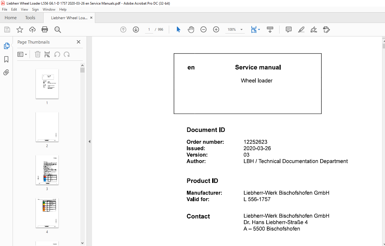
$41
Liebherr Wheel loaders L 566-1757 Service manual – PDF DOWNLOAD
Liebherr Wheel loaders L 566-1757 Service manual – PDF DOWNLOAD
IMAGES PREVIEW OF THE MANUAL:
FILE DETAILS:
Liebherr Wheel loaders L 566-1757 Service manual – PDF DOWNLOAD
Language : English
Pages :996
Downloadable : Yes
File Type : PDF
Size: 220 MB
DESCRIPTION:
Liebherr Wheel loaders L 566-1757 Service manual – PDF DOWNLOAD
PrefaceNotes for users
- This service manual is designed for trained specialist staff of the Liebherr organisation and their dealers.
- This service manual contains specialist knowledge for repairing Liebherr construc- tion machines. Basic specialist knowledge on electronics, hydraulics, mechanics and engine technology is not contained in this service manual. Therefore special- ized training and qualifications are necessary. Liebherr recommends participating in the Liebherr training program for construction machines.
In this service manual you will find information on:
— Special tools— Technical data— Maintenance intervals and maintenance tasks— Adjustment procedures— Structure and function descriptions— Removal and installation tasks— Circuit diagrams, hydraulic plans and technical drawings
- You will find information on controls and operation in the operator’s manual. Information on spare parts are in the spare parts catalogue. Please observe the local accident prevention laws.
- You can find information on repairs of machine parts in the service documentation under “Wheel loader – repair instructions”.
Introduction:
Intended Use:1.1. Laws, Rules, Guidelines and Safety Regulations
To ensure safe operation:
- Consult with the worksite manager about safety regulations at the place of use.
- Adhere to safety regulations at the place of use.
- Follow traffic regulations.
- Adhere to valid guidelines provided by insurers (for example, employers’ professional liability insurance companies, accident insurance, etc.).
- Avoid working methods that can endanger safety.
- Follow all intervals specified for recurrent checks and inspections as outlined in this operator’s manual.
1.2. Intended Use of Wheel Loader
The wheel loader is used to pick up, move, and dump the following materials:
- Soil
- Stones
- Broken rocks
- Bulk materials
This applies to a standard machine under normal operating conditions. Special applications are described in a separate options operator’s manual.
To ensure the intended use:
- Adhere to the operator’s manual.
- Follow maintenance intervals.
- Carry out inspection and maintenance tasks.
- Follow the specifications in the technical data.
- When using the machine on public roads, ensure it complies with applicable national regulations.
- Only lift loads with intended working attachments (fork prongs, crane boom), which must be properly fitted and functioning.
- Ensure that machines used underground (for mining and tunnel construction) are fitted with systems to reduce exhaust emissions (such as diesel particulate filters).
- Adhere to the requirements of each individual country for underground operation.
- For special uses, use special working attachments and, if necessary, special safety equipment.
- Exclusively mount and use special working attachments with approval and as per the stipulations of the manufacturer of the basic machine.
TABLE OF CONTENTS:
Liebherr Wheel loaders L 566-1757 Service manual – PDF DOWNLOAD
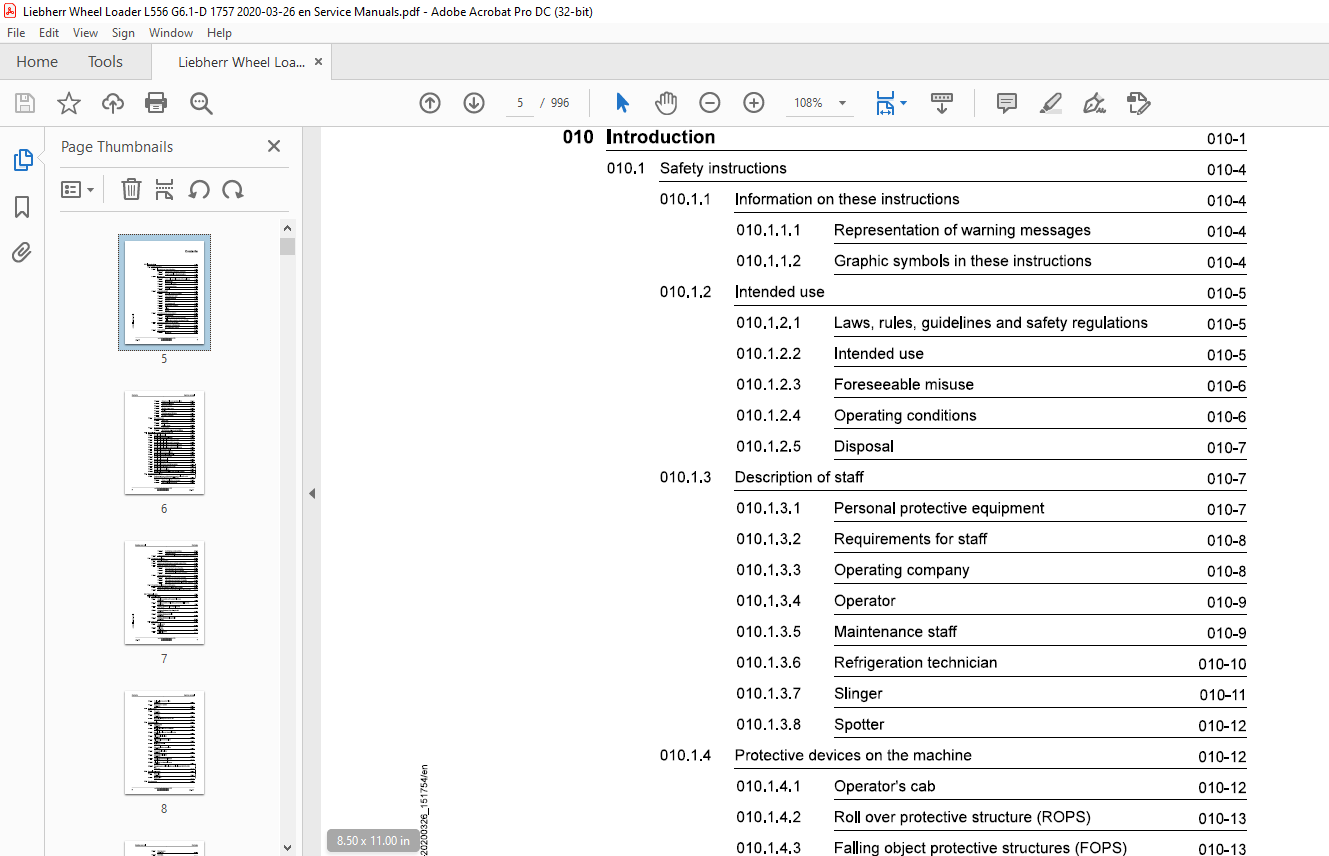
010 Introduction 010-1
010.1 Safety instructions 010-4
010.1.1 Information on these instructions 010-4
010.1.1.1 Representation of warning messages 010-4
010.1.1.2 Graphic symbols in these instructions 010-4
010.1.2 Intended use 010-5
010.1.2.1 Laws, rules, guidelines and safety regulations 010-5
010.1.2.2 Intended use 010-5
010.1.2.3 Foreseeable misuse 010-6
010.1.2.4 Operating conditions 010-6
010.1.2.5 Disposal 010-7
010.1.3 Description of staff 010-7
010.1.3.1 Personal protective equipment 010-7
010.1.3.2 Requirements for staff 010-8
010.1.3.3 Operating company 010-8
010.1.3.4 Operator 010-9
010.1.3.5 Maintenance staff 010-9
010.1.3.6 Refrigeration technician 010-10
010.1.3.7 Slinger 010-11
010.1.3.8 Spotter 010-12
010.1.4 Protective devices on the machine 010-12
6 Safe operation 010-14
010.1.6.1 Intoxicants 010-14
copylight © Liebherr-Werk Bischofshofen GmbH 2020
L556-1757 llEBHERR 5
Contents Service manual
010.1.6.2 Dangerous fuels and operating fluids 010-14
010.1.6.3 Transporting machine 010-15
010.1.6.4 Access to machine 010-15
010.1.6.5 Machine danger zone 010-16
010.1.6.6 Visibility 010-16
010.1.6.7 Protection against vibration 010-17
010.1.6.8 Operation of machine 010-18
010.1.7 Safe maintenance 010-21
010.1.7.1 Spare parts 010-21
010.1.7.2 Heavy parts 010-21
010.1.7.3 Regular checks 010-22
010.1.8 Modifications to the machine 010-22
010.1.8.1 Modifications, add-ons and retrofittings 010-22
010.2 Special tools for maintenance and repair work 010-23
010.2.1 Special tools, general 010-23
010.2.2 Special tools for the diesel engine 010-25
010.2.3 Special tools for lift cylinders with Z kinematics 010-29
010.2.4 Special tools for tilt cylinders with Z kinematics 010-29
010.2.5 Special tools for lift cylinders with industrial lift arms 010-30
010.2.6 Special tools for tilt cylinders with industrial lift arms 010-31
010.2.7 Special tools for steering wheel 010-31
010.2.8 Special tools for steering cylinders 010-32
010.2.9 Special tools for the electrical system 010-32
010.2.10 Special tools for the transmission 010-33
010.2.11 Special tools for front axle 010-34
010.2.12 Special tools for rear axle 010-35
010.2.13 Special tools for the air conditioning system 010-35 C:
010.3.1.1 Range of application and purpose 010-38
010.3.1.2 Other applicable documents 010-38
copylight © Liebherr-Werk Bischofshofen GmbH 2020
6 llEBHERR L556-1757
Service manual
010.3.1.3
010.3.1.4
Modifications and descriptions
Tightening torques
010.3.2 Liebherr standards for assembly instructions and tightening torqueso10-45
010.4 Preservation guidelines
010.4.1 General information
010.4.2 Machine out of service for an unknown period of time
010.4.3 Putting the machine out of service
Out of service for up to 2 months
Out of service for up to 12 months
Out of service for longer than 12 months
010.4.4 Putting back into service
After being out of service for 2 months
After being out of service for 12 months
010.4.4.3 After being out of service for longer than 12 months 010-50
010.5 Preservation guidelines for the SCR system
010.5.1 Putting out of service for longer than 2 months
010.5.2 Starting up after being out of service for longer than 2 months
020 Technical data 020-1
L556-1757
020.1 Overall machine
020.1.1 Complete machine with bucket (Z lift arms)
L556-1757;
020.1.2 Complete machine with loading bucket (industrial lift arms)
L556-1757;
020.1.3 Working attachment: light material bucket
L556-1757;
020.1.4 Working attachment: high dump bucket
L556-1757;
020.1.5 Working attachment: forklift
L556-1757;
020.1.6 Working attachment: log grappler
L556-1757;
020.2 Drive group
020.2.1 Diesel engine
L556-1757;
020.2.2 Fuel tank
L556-1757;
020.2.3 Fuel level sensor
L556-1757;
Contents Service manual
020.2.4 Fuel pre-filter (separator filter)
L556-1757; 020-16
020.2.5 Compressed air system
L556-1757; 020-17
020.3 Cooling system 020-18
020.3.1 Fan pump
L556-1757; 020-18
020.3.2 Fan motor
L556-1757; 020-18
020.3.3 Hydraulic oil temperature sensor B8
L556-1757; 020-18
020.4 Working hydraulics 020-19
020.4.1 Working pump
L556-1757; 020-19
020.4.2 Control valve block for Z kinematics
L556-1757; 020-19
020.4.3 Control valve block for industrial lift arms
L556-1757; 020-20
020.4.4 Pilot control valve block
L556-1757; 020-20
020.4.5 Pilot control hydro accumulator
L556-1757; 020-20
020.4.6 Stabilisation module
L556-1757; 020-21
020.4.7 Ride control hydro accumulator
L556-1757; 020-21
020.4.8 Z kinematics lift cylinder
L556-1757; 020-21
020.4.9 Z kinematics tilt cylinder
L556-1757; 020-21
020.4.10 Lift cylinder for industrial lift arms
L556-1757; 020-22
020.4.11 Tilt cylinder for industrial lift arms
020.6 Steering system 020-25
copylight © Liebherr-Werk Bischofshofen GmbH 2020
8 llEBHERR L556-1757
Service manual Contents
020.6.1 Steering pump
L556-1757; 020-25
020.6.2 Servostat
L556-1757; 020-25
020.6.3 Steering cylinder
L556-1757; 020-25
020.6.4 Steering damper hydro accumulator
L556-1757; 020-26
020.6.5 Emergency steering pump
L556-1757; 020-26
020.6.6 Emergency steering pressure switch B3
L556-1757; 020-26
020.6.7 Emergency steering check pressure switch B3a
L556-1757; 020-26
020.6.8 Joystick steering control valve block
L556-1757; 020-27
020.7 Brake system 020-28
020.7.1 Brake pump
L556-1757; 020-28
020.7.2 Compact brake valve
L556-1757; 020-28
020.7.3 Service brake hydro accumulator
L556-1757; 020-28
020.7.4 Brake light pressure switch B12
L556-1757; 020-28
020.7.5 Brake accumulator pressure sensor B19
L556-1757; 020-29
020.7.6 Parking brake hydro accumulator
L556-1757; 020-29
020.8 Electrical system 020-30
020.8.1 Central control unit (Master5-Premium)
L556-1757; 020-30
020.8.2 Input module
L556-1757; 020-31
020.9 Gearbox 020-32
copylight © Liebherr-Werk Bischofshofen GmbH 2020
L556-1757 llEBHERR 9
Contents Service manual
020.9.1 Transmission
L556-1757; 020-32
020.9.2 Filter bypass switch B85
L556-1757; 020-32
020.9.3 Proportional solenoid for gear shifting Y1, Y2, Y3, Y4, Y5, Y6
L556-1757; 020-32
020.9.4 Pressure sensor for hydrostat B80, B81
L556-1757; 020-33
020.9.5 Speed sensor B82, B83, B84
L556-1757; 020-33
020.9.6 Transmission oil temperature sensor B86
L556-1757; 020-33
020.9.7 Proportional solenoid for position control Y7
L556-1757; 020-34
020.10 Axles and drive shafts 020-35
020.10.1 Front axle
L556-1757; 020-35
020.10.2 Rear axle
L556-1757; 020-35
020.10.3 Cardan shaft between engine and transmission
L556-1757; 020-35
020.10.4 Cardan shaft between transmission and front axle
L556-1757; 020-36
020.10.5 Drive shaft between transmission and rear axle
L556-1757; 020-36
020.10.6 Tyres
L556-1757; 020-36
020.10.6.2 Tyres for timber work 020-37
020.10.6.3 Special tyres 020-38
020.11 Steel parts of the basic machine 020-39
020.11.1 Ballast weights
L556-1757; 020-39
020.11.1.1 Standard (Z kinematics) 020-39 C:
020.13.1.1 Air conditioning compressor 020-41
020.13.2 Air conditioning pressure switch
L556-1757; 020-41
copylight © Liebherr-Werk Bischofshofen GmbH 2020
10 llEBHERR L556-1757
Service manual
020.14 Lubrication system
020.14.1 Central lubrication system (Liebherr)
L556-1757;
020.14.1.1 Central lubrication pump
020.14.1.2 Progressive distributor
020.14.2 Progressive distributor
020-42
L556-1757; 020-43
020.14.2.1 MX-F 020-43
020.14. 2. 2 MX-F 25 020-43
020.14. 2. 3 MX-F 45 020-44
020.14.2.4 MX-F 75 020-44
020.14. 2. 5 MX-F105 020-44
020.14.3 Progressive distributor SXE-2
L556-1757; 020-44
020.14.3.1 SXE-2 / MX-F 020-44
020.14.3.2 SXE-2 100 020-44
020.14.3.3 SXE-2 150 020-45
020.14. 3 .4 SXE-2 220 020-45
020.14.3.5 SXE-2 400 020-45
020.14. 3. 6 SXE-2 760 020-45
030 Maintenance 030-1
030.1 Maintenance and inspection schedule
030.2 Filling quantities and lubrication chart
030.2.1 Lubricant filling quantity
General questions
Safety data sheets
Technical data sheets
Specific Liebherr standards
General information on changing lubricants and fuels
Converting hydraulic system from mineral oils to biodegradable
hydraulic fluids
Contents Service manual
030.3.4 Diesel fuels
L556-1757; 030-18
030.3.4.1 Minimum quality requirement 030-18
030.3.4.2 Operating temperatures of diesel fuels 030-19
030.3.4.3 Minimum quality requirement 030-19
030.3.5 Diesel exhaust fluid
L556-1757; 030-19
030.3.5.1 Liebherr recommendation 030-19
030.3.5.2 Minimum quality requirement 030-19
030.3.6 Engine oils
L556-1757; 030-20
030.3.6.1 Liebherr recommendation 030-20
030.3.6.2 Minimum quality requirement 030-20
030.3.6.3 Changing intervals 030-20
030.3.6.4 Complicating factors 030-21
030.3.7 Refrigerant
L556-1757; 030-21
030.3.8 Coolant
L556-1757; 030-22
030.3.8.1 Requirements for the water used 030-22
030.3.8.2 Antifreeze and corrosion inhibitor 030-22
030.3.8.3 Minimum quality requirement 030-22
030.3.9 Hydraulic oil
L556-1757; 030-22
030.3.9.1 Liebherr recommendation 030-22
030.3.9.2 Minimum quality requirement 030-23
030.3.9.3 Oil analysis 030-23
030.3.9.4 Oil change 030-23
030.3.10 Splitter box oil
030.3.12 Axle oil
L556-1757; 030-25
030.3.12.1 Liebherr recommendation 030-25
copylight © Liebherr-Werk Bischofshofen GmbH 2020
12 llEBHERR L556-1757
Service manual Contents
030.3.12.2 Minimum quality requirement 030-25
030.3.13 Lubrication grease
L556-1757; 030-25
030.3.13.1 Liebherr recommendation 030-25
030.3.13.2 Minimum quality requirement 030-25
030.3.14 Windscreen washer fluid
L556-1757; 030-26
030.3.14.1 Liebherr recommendation 030-26
030.3.14.2 Minimum quality requirement 030-26
030.3.15 Refrigerant oil for air conditioning compressor
L556-1757; 030-26
030.3.15.1 Liebherr recommendation 030-26
030.4 Maintenance tasks 030-27
030.4.1 Safety precautions
L556-1757; 030-27
030.4.2 Preparatory tasks for maintenance 030-27
030.4.2.1 Maintenance positions
L556-1757; 030-28
030.4.2.2 Opening the service hatches
L556-1757; 030-29
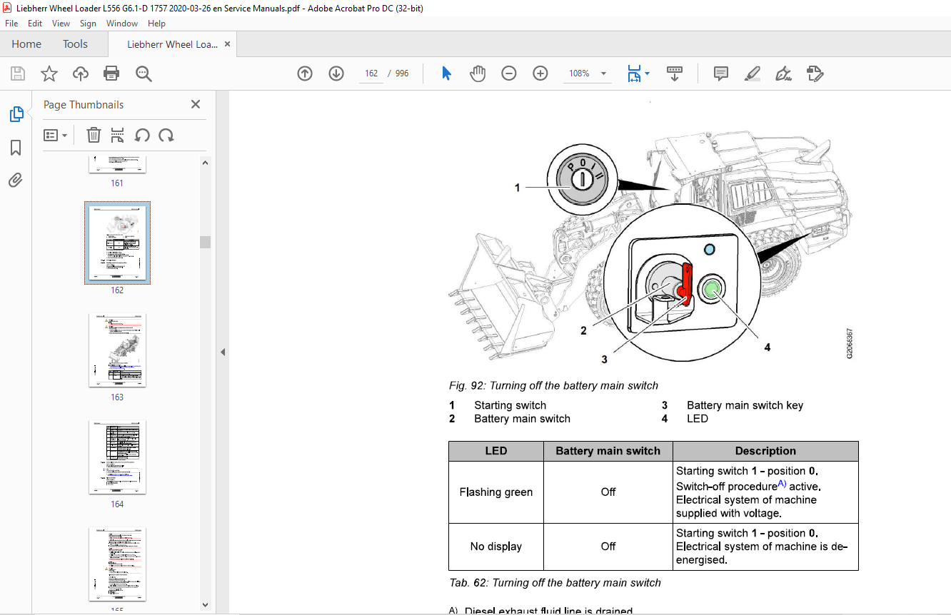
030.4.2.3 Turning off the battery main switch
L556-1757; 030-33
030.4.3 Overall machine 030-34
030.4.3.1 Checking machine is in proper condition
L556-1757; 030-34
030.4.3.2 Removing loose parts, dirt, ice and snow from
machine
L556-1757; 030-36
030.4.3.3 Cleaning machine
L556-1757; 030-36
030.4.3.4 Changing the VCl-capsules
030.4.4.3 Diesel engine: changing oil filter
L556-1757; 030-55
copylight © Liebherr-Werk Bischofshofen GmbH 2020
L556-1757 llEBHERR 13
Contents Service manual
030.4.4.4 Checking diesel engine belt drive
L556-1757; 030-56
030.4.4.5 Changing diesel engine belt drive
L556-1757; 030-57
030.4.4.6 Checking fastening of diesel engine control units and
sensor cable connections
L556-1757; 030-58
030.4.4.7 Checking diesel engine valve clearance
L556-1757; 030-59
030.4.4.8 Diesel engine: changing oil separator filter cartridge
L556-1757; 030-61
030.4.4.9 Diesel engine: Changing the heating flange
L556-1757; 030-62
030.4.4.10 Fuel tank: Draining off condensate and sediment
L556-1757; 030-62
030.4.4.11 Fuel pre-filter: Draining off condensate
L556-1757; 030-63
030.4.4.12 Changing fuel pre-filter cartridge
L556-1757; 030-64
030.4.4.13 Changing fuel fine filter element
L556-1757; 030-67
030.4.4.14 Diesel exhaust fluid tank: checking ventilation
L556-1757; 030-70
030.4.4.15 Air filter system: Cleaning the service cover and dust
discharge valve
L556-1757; 030-71
030.4.4.16 Cleaning or changing the main element of the air
filter system
L556-1757; 030-72
030.4.4.17 Air filter system: Changing the safety element
L556-1757; 030-75
030.4.4.18 Dust protection for alternator (option): cleaning or
replacing filter element
L556-1757; 030-76
030.4.4.19 Splitter box: Checking the oil level C:
030.4.4.21 Checking that the diesel engine intake and exhaust 0
system is in good condition and not loose or leaking ~
L556-1757; 030-82 ~030.4.4.22 Checking the diesel engine for leaks, contamination “‘ ~ and damage ID
L556-1757; 030-84
030.4.4.23 Diesel engine: checking profile clamps
L556-1757; 030-85
copylight © Liebherr-Werk Bischofshofen GmbH 2020
14 llEBHERR L556-1757
Service manual Contents
030.4.4.24 Diesel particulate filter: Cleaning filter module
L556-1757; 030-87
030.4.4.25 Changing the compressed air dryer
L556-1757; 030-90
030.4.4.26 Checking compressed air system
L556-1757; 030-91
030.4.5 Cooling system 030-92
030.4.5.1 Cooling system: Checking the coolant level
L556-1757; 030-92
030.4.5.2 Coolant: checking anti-freeze and corrosion protection
agent concentration
L556-1757; 030-93
030.4.5.3 Cleaning the cooling system
L556-1757; 030-100
030.4.5.4 Changing coolant in cooling system
L556-1757; 030-101
030.4.6 Hydraulic components 030-104
030.4.6.1 Hydraulic tank: Checking the oil level
L556-1757; 030-104
030.4.6.2 Draining off condensate and sediment from the
hydraulic tank
L556-1757; 030-106
030.4.6.3 Change the return filter insert in the hydraulic tank.
L556-1757; 030-107
030.4.6.4 Changing the hydraulic tank breather filter
L556-1757; 030-108
030.4.6.5 Hydraulic tank: analysing the oil
L556-1757; 030-109
030.4.6.6 Changing the oil in the hydraulic tank
L556-1757; 030-110
030.4.7 Steering system 030-114
030.4.7.1 Steering: Checking the function
L556-1757; 030-114
C: 030.4.7.2 Steering cylinders: Lubricating the bearings ,!!?
linings
L556-1757; 030-118
copylight © Liebherr-Werk Bischofshofen GmbH 2020
L556-1757 llEBHERR 15
Contents Service manual
030.4.8.4 Emergency actuation of parking brake: checking the
seal
L556-1757; 030-124
030.4.8.5 Checking emergency parking brake actuation
L556-1757; 030-125
030.4.9 Electrical system 030-126
030.4.9.1 Checking function of the lighting and horn
L556-1757; 030-126
030.4.9.2 Batteries: Checking the acid level and terminals
L556-1757; 030-127
030.4.9.3 Control lever: Change the travel direction switch
rocker and cap.
L556-1757; 030-129
030.4.9.4 Personnel detection: cleaning sensor
L556-1757; 030-131
030.4.10 Gearbox 030-132
030.4.10.1 Transmission: checking the oil level
L556-1757; 030-132
030.4.10.2 Changing gear oil and gear oil filter
L556-1757; 030-135
030.4.10.3 Change the transmission hydrostat oil filter.
L556-1757; 030-138
030.4.11 Axles and drive shafts 030-139
030.4.11.1 Axles Changing the oil
L556-1757; 030-139
030.4.11.2 Checking drive shafts
L556-1757; 030-141
030.4.11.3 Checking the tyre pressure
L556-1757; 030-143
030.4.11.4 Checking the wheel tightness
L556-1757; 030-145
030.4.12 Steel parts of the basic machine 030-145
030.4.12.1 Lubricating the articulation bearing and the rear axle
oscillating bearing C:
copylight © Liebherr-Werk Bischofshofen GmbH 2020
16 llEBHERR L556-1757
Service manual Contents
030.4.12.5 Service hatches: cleaning and maintaining seals
L556-1757; 030-148
030.4.13 Working attachment 030-149
030.4.13.1 Lubricating the lift arms and working attachment
L556-1757; 030-149
030.4.13.2 Lift arms: Checking the bucket bearing seals
L556-1757; 030-151
030.4.13.3 Lift arms: checking bucket bearing bushings
L556-1757; 030-152
030.4.13.4 Checking the lift arm bucket stops
L556-1757; 030-153
030.4.13.5 Bucket: Check the teeth or undercut blade for wear
and replace if necessary
L556-1757; 030-155
030.4.13.6 Lubricate and test the bearings on the quick coupler.
L556-1757; 030-158
030.4.13.7 High dump bucket: Lubricating the bearing
L556-1757; 030-159
030.4.14 Operator’s cab, heating and air conditioning 030-159
030.4.14.1 Operator’s cab: cleaning the fresh and recirculated
air filters
L556-1757; 030-159
030.4.14.2 Operator’s cab: changing fresh air filter and recirculated
air filters
L556-1757; 030-160
030.4.14.3 Safety belt: Checking the condition and function
L556-1757; 030-162
030.4.14.4 Testing the windscreen washer system
L556-1757; 030-163
030.4.14.5 Windscreen washer system: filling windscreen
washer fluid
L556-1757; 030-163
030.4.15 Lubrication system 030-166
030.4.15.1 Checking the level in the grease reservoir of the “‘ ~ ID central lubrication system
L556-1757; 030-166
030.4.15.2 Central lubrication system: Checking the pipes,
hoses and lubrication points for leaks and damage
L556-1757; 030-167
copylight © Liebherr-Werk Bischofshofen GmbH 2020
L556-1757 llEBHERR 17
Contents
030.5
030.6
18
Service manual
030.4.15.3 Central lubrication system: Checking the lubrication
of the bearings
L556-1757; 030-168
Testing and adjustment checklist
L556-1757; 030-169
Testing and adjustment tasks 030-176
030.6.1
030.6.2
030.6.3
030.6.4
030.6.5
Safety precautions
L556-1757; 030-176
Overall machine 030-176
030.6.2.1 Preparing for adjustment procedures
L556-1757; 030-176
030.6.2.2 Hydraulic oil: operating temperature
L556-1757; 030-178
030.6.2.3 Gear oil operating temperature
L556-1757; 030-179
030.6.2.4 Service management
L556-1757; 030-179
Drive group 030-180
030.6.3.1 Pedals: calibration
L556-1757; 030-180
030.6.3.2 Reading the diesel engine service files
L556-1757; 030-182
Cooling system 030-183
030.6.4.1 Fan speed proportional solenoid valve
L556-1757; 030-183
Working hydraulics 030-185
030.6.5.1 Multi-lever control (optional): Calibration
L556-1757; 030-185
030.6.5.2 Calibrating working hydraulics angle sensors
L556-1757; 030-187
030.6.5.3 Proportional solenoids in the control valve block: calibration
Working pump: flow regulator (standby pressure)
L556-1757;
Working pump flow regulator (differential pressure)
030-195
L556-1757; 030-196
Working pump: power regulator
L556-1757; 030-198
Z-bar kinematics control valve block: secondary pressure
030.6.5.9 Z-bar kinematics control valve block: primary pressure
relief valve
L556-1757; 030-202
030.6.5.10 Z-bar kinematics control valve block: LS-pressure
cut-off
L556-1757; 030-204
030.6.5.11 Industrial lift arms control valve block (option): secondary
pressure relief valves
L556-1757; 030-205
030.6.5.12 Industrial lift arms control valve block (option):
primary pressure relief valve
L556-1757; 030-208
030.6.5.13 Industrial lift arms control valve block (option): LSpressure
cut-off
L556-1757; 030-209
030.6.5.14 Stabilisation module cut-out function
L556-1757; 030-211
030.6.5.15 Ride control hydro accumulator nitrogen filling
L556-1757; 030-212
Hydraulic components 030-213
030.6.7 Steering system 030-219
030.6.7.1 Joystick for joystick steering (option): calibration
L556-1757; 030-219
030.6.7.2 Angle sensor for articulation angle (option): calibration
(machine with steering wheel steering)
L556-1757; 030-219
030.6.7.3 Angle sensor for articulation angle (option): calibration
(machine without steering wheel steering)
L556-1757; 030-221
030.6.7.4 Control block for joystick steering (option): calibration
L556-1757; 030-222
030.6.7.5 Steering pump: LS pressure cut-off valve
L556-1757; 030-224
030.6.7.6 Steering pump flow regulator (standby pressure)
L556-1757; 030-225
030.6.7.7 Steering pump: flow regulator (differential pressure)
L556-1757; 030-227
030.6.7.8 Steering damper hydro accumulator nitrogen filling
L556-1757; 030-228
copylight © Liebherr-Werk Bischofshofen GmbH 2020
llEBHERR 19
Contents Service manual
030.6.7.9 Control block for joystick steering: determining installation
position of position sensors
L556-1757; 030-229
030.6.8 Brake system 030-230
030.6.8.1 Brake accumulator pressure sensor B19: deviation
L556-1757; 030-230
030.6.8.2 Compact brake valve hydro accumulator charging
function
L556-1757; 030-231
030.6.8.3 Service brake pressure
L556-1757; 030-232
030.6.8.4 Service brake hydro accumulator capacity
L556-1757; 030-233
030.6.9 Electrical system 030-235
030.6.9.1 Central control unit (Master5): creating service file
L556-1757; 030-235
030.6.9.2 Central control unit (Master5): software update
L556-1757; 030-236
030.6.9.3 Central control unit (Master5): resetting to factory
settings
L556-1757; 030-239
030.6.9.4 Central control unit (Master5): connecting Sculi diagnostic
software
L556-1757; 030-241
030.6.9.5 Central control unit (Master5): connecting LiFT function
L556-1757; 030-244
030.6.9.6 Addressing CAN module and checking system information
L556-1757; 030-245
030.6.10 Gearbox 030-249
030.6.10.1 Gearbox: basic calibration
L556-1757; 030-249
030.6.10.2 Gearbox: service calibration
L556-1757; 030-256
copylight © Liebherr-Werk Bischofshofen GmbH 2020
20 llEBHERR L556-1757
Service manual Contents
L556-1757
030.6.12.2 Parameters for lift arm geometry
L556-1757; 030-257
030.6.12.3 Working attachment: automatic return of 3rd function
L556-1757; 030-258
030.6.13 Operator’s cab, heating and air conditioning 030-259
030.6.13.1 Checking the pressure and temperature conditions of
the air conditioning unit
L556-1757; 030-259
030.6.14 Options 030-260
040 Drive group
040.1 Engine
030.6.14.1 LiDAT: connecting to LiDAT module
L556-1757;
030.6.14.2 LiDAT: software update for LiDAT module
L556-1757;
030.6.14.3 LiDAT: creating report and snapshot
L556-1757;
030-260
030-262
030-264
030.6.14.4 Liebherr weighing device with Truck Payload Assist:
calibration
L556-1757; 030-268
030.6.14.5 Skyview 360°: calibration
L556-1757;
030.6.14.6 Personnel detection: transmitting configuration files
030-268
L556-1757; 030-275
030.6.14.7 Tyre pressure monitoring: changing and programming
pressure sensor
Contents Service manual
040.1.7 Exhaust system 040-23
040.1.7.1 Exhaust gas treatment (stage V): overview
L556-1757; 040-24
040.1.7.2 Exhaust gas treatment (stage IV/ tier 4f): overview
L556-1757; 040-33
040.1.7.3 Metering unit
L556-1757; 040-38
040.1.7.4 Sampling module
L556-1757; 040-41
040.1.7.5 Exhaust treatment sensors
L556-1757; 040-42
040.1.8 Compressed air system 040-43
040.1.8.1 Overview of the compressed air system
L556-1757; 040-44
040.1.8.2 Compressor
L556-1757; 040-46
040.1.8.3 Air dryer
L556-1757; 040-47
040.1.8.4 SCR system air supply valve
L556-1757; 040-48
040.2 Clutch
L556-1757; 040-49
040.3 Splitter box
L556-1757; 040-51
050 Cooling system 050-1
050.1 Cooling system: General overview
L556-1757; 050-2
050.2 Cooling system hydraulics 050-3
050.2.1 Overview of cooling system hydraulics
L556-1757; 050-4
050.2.2 Fan pump
L556-1757; 050-8
050.4 Cooler 050-18
050.4.1 Cooler unit
L556-1757; 050-18
copylight © Liebherr-Werk Bischofshofen GmbH 2020
22 llEBHERR L556-1757
Service manual Contents
050.5 Reversible fan drive 050-19
050.5.1 Overview of reversible fan drive
L556-1757; 050-19
050.5.2 Fan reversal valve block
L556-1757; 050-21
060 Working hydraulics 060-1
060.1 Overview of Z-bar kinematics working hydraulics
L556-1757; 060-3
060.2 Overview of working hydraulics for industrial lift arms
L556-1757; 060-12
060.3 Working pump
L556-1757; 060-16
060.4 Control block for Z-bar kinematics
L556-1757; 060-24
060.5 Control valve block for industrial lift arms
L556-1757; 060-32
060.6 Pilot control 060-39
060.6.1 Pilot control valve block
L556-1757; 060-39
060.7 Ride control 060-41
060.7.1 Overview of ride control system
L556-1757; 060-41
060.7.2 Stabilisation module
L556-1757; 060-44
060.7.3 Electric ride control unit
L556-1757; 060-47
060.8 Electronics of the working hydraulics 060-49
060.8.1 Overview of electrical controls the working hydraulics
L556-1757; 060-49
060.8.2 Working hydraulics angle sensors
Service manual
Hydraulic components
080.1 Hydraulic system: overview
080.2 Hydraulic tank
080.2.1 Overview of hydraulic tank
080.2.2 Steel tank
080.2.3 Return filter
080.2.4 Leak oil strainer
080.2.5 Breather filter
Steering system
Steering system overview
Steering pump
Servostat
Steering cylinder
090.4.1 Steering cylinder
090.4.2 Steering stabilisation valve block
090.4.3 Valve block for steering stabilisation (without steering wheel
steering)
090.5 Emergency steering
Emergency steering overview
Emergency steering pump
Emergency steering electronics
Overview of electrical controls of emergency steering
system
Emergency steering pressure switch
Emergency steering check pressure switch
Service manual Contents
L556-1757
090.6 Joystick steering 090-35
090.6.1 Joystick steering: overview (combined with steering wheel steering)
L556-1757; 090-35
090.6.2 Joystick steering: overview (without steering wheel steering)
L556-1757;
090.6.3 Joystick steering control block
L556-1757;
090.6.4 Joystick steering electrical system
090.6.4.1 Electronic control unit for joystick steering: overview
L556-1757; 090-48
090.6.4.2
090.7 2in1 steering
Joystick with position tracking
L556-1757;
090. 7 .1 2in 1 steering: total overview
L556-1757;
090.7.2 Servostat for 2in1 steering
L556-1757;
100 Brake system
100.1 Overview of brake system
L556-1757;
100.2 Service brake and parking brake
100.2.1 Brake pump
L556-1757;
100.2.2 Compact brake valve
L556-1757;
100.3 Parking brake
100.3.1 Parking brake
L556-1757;
110 Electrical system
110.1 Overview of electrical system
L556-1757;
110.2 Lighting
L556-1757;
110.3 Circuit diagrams
L556-1757;
110.4 Electronic control unit
110.4.1 General overview of electronic control system
L556-1757;
110.4.2 Central control unit (Masters-Premium)
L556-1757;
Contents Service manual
110.4.3 Modules 110-14
110.4.3.1 Overview of the input and output modules
L556-1757; 110-14
110.4.3.2 Input modules
L556-1757; 110-17
110.4.3.3 Output modules
L556-1757; 110-18
110.5 Electrical components of the driver’s cab 110-21
110.5.1 Fuse and relay boards
L556-1757; 110-21
110.5.2 Door contact switch (inductive sensor)
L556-1757; 110-26
110.6 Electrical components in the rear section 110-27
110.6.1 Battery installation
L556-1757; 110-27
110.6.2 Electric battery main switch
L556-1757; 110-29
120 Gearbox 120-1
120.1 Overview of transmission
L556-1757; 120-2
120.2 Transmission hydraulics 120-15
120.2.1 Overview of transmission hydraulics
L556-1757; 120-15
120.2.2 Gear pump
L556-1757; 120-19
120.2.3 Transmission control valve block
L556-1757; 120-20
120.2.4 Hydrostat module
L556-1757; 120-23
120.3 Transmission electronics 120-28
120.3.1 Overview of electrical control system of transmission
L556-1757; 120-28 C:
120.3.3 Gear shifting proportional solenoid “0 ‘
L556-1757; 120-30 ~ ~
120.3.4 Pressure sensor for hydrostat ~
“”” L556-1757; 120-31 “”””’
120.3.5 Engine speed sensor ~ ID
…J
L556-1757; 120-32
120.3.6 Temperature sensor
L556-1757; 120-33
copylight © Liebherr-Werk Bischofshofen GmbH 2020
26 llEBHERR L556-1757
Service manual
L556-1757
130
120.3.7 Proportional solenoid for position control
L556-1757;
Axles and drive shafts
130.1
130.2
Axles
130.1.1 Front axle
L556-1757;
130.1.2 Rear axle
L556-1757;
Cardan shafts
130.2.1 Drive shaft between diesel engine and transmission
L556-1757;
130.2.2 Drive shaft between transmission and front axle
L556-1757;
130.2.3 Drive shaft between transmission and rear axle
L556-1757;
140 Steel parts of the basic machine
140.1 Vehicle frame
140.1.1 Articulation bearing
L556-1757;
140.1.2 Articulation lock
L556-1757;
140.2 Covering
140.2.1 Linear motor for opening the engine hood
L556-1757;
150 Working attachment
150.1 Lift arms for Z kinematics
150.1.1 Z kinematics
L556-1757;
150.2 Industrial lift arms
150.2.1 Industrial lift arms
L556-1757;
150.3 Quick coupler
150.3.1 Quick coupler
L556-1757;
150.3.2 Quick coupler hydraulics
150.3.2.1
150.3.2.2
Overview of quick coupler hydraulics
L556-1757;
Valve block for quick coupler
Contents Service manual
150.3.3 Quick coupler electrics 150-11
150.3.3.1 Quick coupler electric control unit
L556-1757; 150-11
160 Operator’s cab, heating and air conditioning 160-1
160.1 Overview of operator’s cab, heating and air conditioning unit
L556-1757; 160-2
160.2 Display and control elements 160-4
160.2.1 Control lever
L556-1757; 160-4
160.2.2 Accelerator pedal
L556-1757; 160-6
160.3 Heating, ventilation, air conditioning 160-8
160.3.1 Heating, ventilation, air conditioning: General overview
L556-1757; 160-8
160.3.2 Heating and air conditioning unit 160-13
160.3.2.1 Heating and air conditioning unit
L556-1757; 160-14
160.3.2.2 Blower
L556-1757; 160-18
160.3.3 Air conditioning controller
L556-1757; 160-19
160.4 Air conditioning 160-22
160.4.1 Basic function of the air conditioning unit
L556-1757; 160-22
160.4.2 Air conditioning compressor
L556-1757; 160-23
160.4.3 Condenser
L556-1757; 160-25
160.4.4 Dryer
L556-1757; 160-26
160.4.5 Air conditioning pressure switch
L556-1757; 160-27 C:
170.1.2 Liebherr central lubrication pump ~ ID
L556-1757; 170-8 …J
170.1.3 Progressive distributor MX-F
L556-1757; 170-12
copylight © Liebherr-Werk Bischofshofen GmbH 2020
28 llEBHERR L556-1757
Service manual Contents
170.1.4 Progressive distributor SXE-2
L556-1757; 170-14
190 Options 190-1
190.1 LiDAT 190-2
190.1.1 Overview of LiDAT
L556-1757; 190-2
190.1.2 LiDAT on machine
L556-1757; 190-4
190.1.3 LiDAT module (LiTU3)
L556-1757; 190-6
190.2 Liebherr weighing device with Truck Payload Assist
L556-1757; 190-10
190.3 Skyview 360° 190-12
190.3.1 Skyview 360°: complete overview
L556-1757; 190-12
190.3.2 Skyview 360° on machine
L556-1757; 190-16
190.4 Remote control for door lock
L556-1757; 190-17
190.5 Personnel detection
L556-1757; 190-20
190.6 Entfall des Lenkstockschalters 190-23
190.6.1 Elimination of steering-column switch: overview
L556-1757; 190-23
190.6.2 Additional controller (HY-TTC-30S)
L556-1757; 190-25
190.7 Silobetrieb 190-28
190.7.1 Silo operation: overview
L556-1757; 190-28
190.7.2 Tilt sensor for silo operation
L556-1757; 190-30200.1.2 SCR system warning symbols 200-3
200.1.3 Service code indicator in display 200-4 “‘ ~ ID 200.2 Troubleshooting 200-6 …J
200.2.1 Replacing fuses 200-6
200.2.1.1 Fuses on fuse board A4 in the operator’s cab 200-6
Fuses on fuse board A4a in the left ballast weight 200-9
Fuses on fuse board A4b in the operator’s cab 200-11
More products