$35
Manitowoc Crane 3900 Parts Manual SN 39107 PDF
Manitowoc Traditional Crane 3900 Parts Manual SN 39107 – PDF DOWNLOAD
FILE DETAILS:
The Manitowoc Traditional Crane 3900 Parts Manual (SN 39107) in PDF format is an essential resource for maintenance. With detailed diagrams and authentic part details, it simplifies repairs and servicing for the Manitowoc Traditional Crane 3900 with serial number 39107.
Manitowoc Traditional Crane 3900 Parts Manual SN 39107 – PDF DOWNLOAD
Manitowoc Crane 3900 Parts Manual SN 39107 PDF
Language : English
Pages : 214
Downloadable : Yes
File Type : PDF
IMAGES PREVIEW OF THE MANUAL:
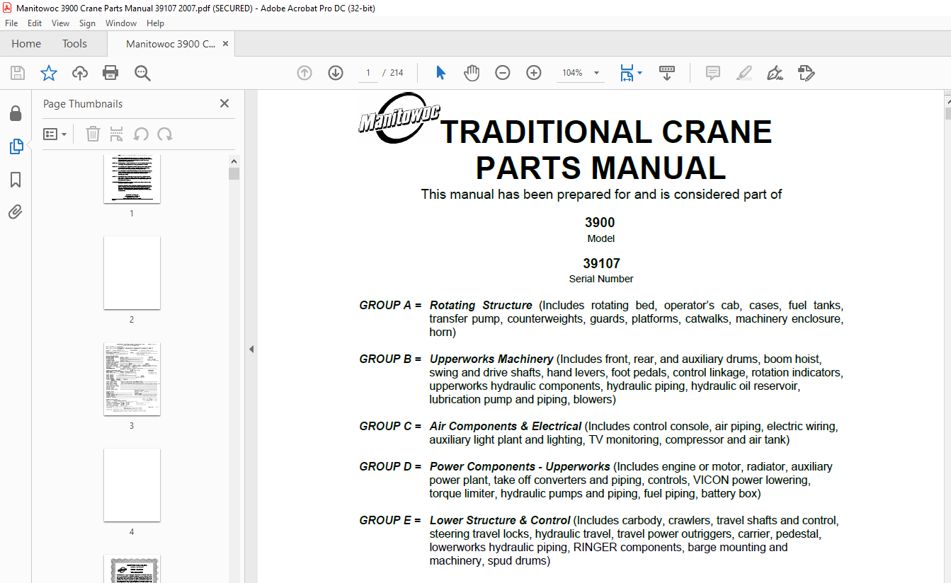
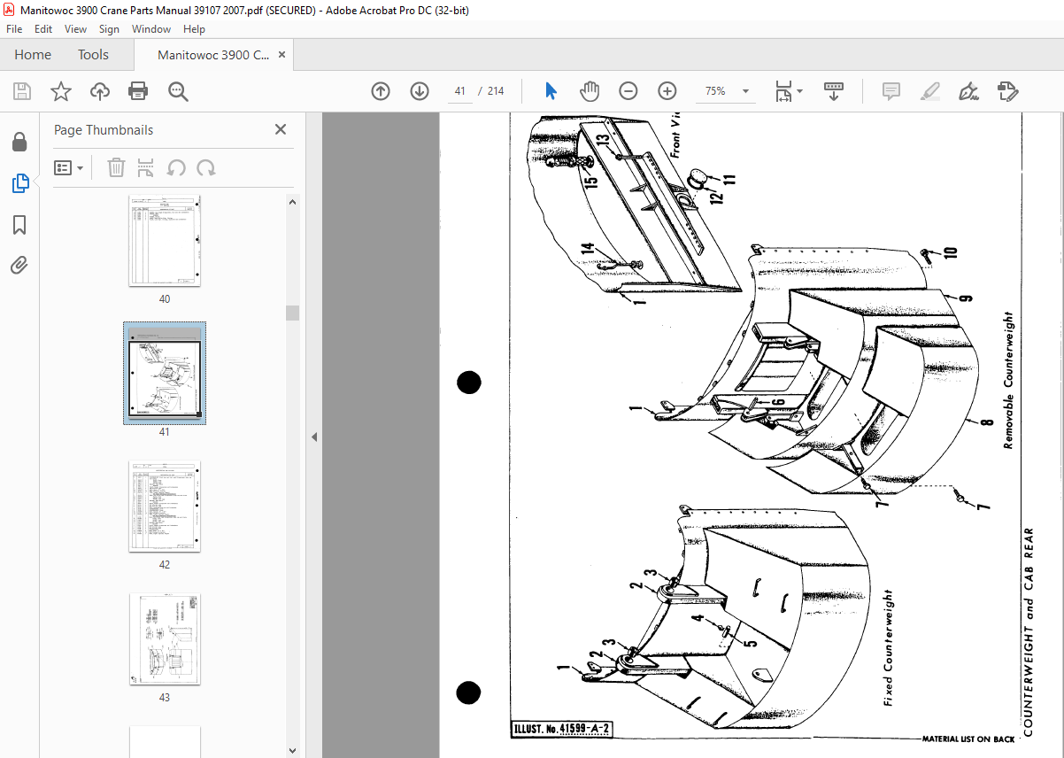
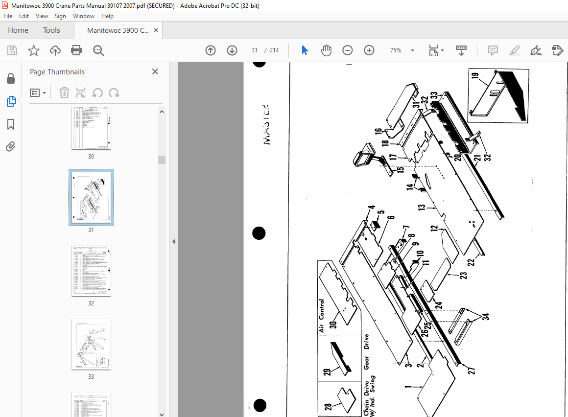
TABLE OF CONTENTS:
Manitowoc Traditional Crane 3900 Parts Manual SN 39107 – PDF DOWNLOAD
Description Approx Weight
LIFTCRANE – (“A” machine) w/38″ treads, counterweight, 140′
No 4 boom, 60 Ton gantry & back hitch, Block, Ind boom hoist 190,550 Lbs
LIFTCRANE – (“B” machine) w/48″ treads, counterweight, 140′
No 4 boom, 80 Ton gantry & back hitch, Block, Ind boom hoist,
Ind swing 206,826 Lbs
UPPER WORKS – (“A” machine) w/Ind, boom hoist Less counterweight,
boom, gantry & back hitch and block 48,840 Lbs
UPPER WORKS – (“B” machine) w/Ind, boom hoist Less counterweight,
boom, gantry & back hitch, block and ind swing 53,553 Lbs
CARBODY w/Roller path, ring gear & king pin, less crawlers 30,720 Lbs
CRAWLER – 20′ 4″ long w/48″ treads (Double weight for two) 23,620 Lbs
CRAWLER – 20′ 4″ long w/38″ treads (Double weight for two) 19,317 Lbs
SELF REMOVING CWT (! Pc or 2 Pc combination) 50,645 or 58,500 Lbs
SELF REMOVING CWT (Outer section of 2 Pc ) 23,000 or 26,500 Lbs
BOOM NO 4 (65 TON)
Boom Base – 65 Ton 3,540 Lbs
Boom Top – 65 Ton (equipped) 4,345 Lbs
10′ Insert – parallel 1,110 Lbs
15′ Insert – parallel 1,430 Lbs
20′ Insert – parallel 1,890 Lbs
25′ Insert – cambered 2,200 Lbs
30′ Insert – cambered 2,870 Lbs
40′ Insert – cambered 3,420 Lbs’
45′ Insert – cambered 4,100 Lbs
50′ Insert – cambered 4,750 Lbs
10′ Insert – tapered 1,150 Lbs
25′ Insert – tapered-deep parallel 2,490 Lbs
10′ Insert – deep parallel 1,190 Lbs
15′ Insert – deep parallel 1,750 Lbs
20′ Insert – deep parallel 2,110 Lbs
BOOM NO 5 (80 TON)
Boom Base – 80 Ton (35′ Long) 5,500 Lbs
Boom Top – 80 Ton (35′ Long – equipped) 6,350 Lbs
10′ Insert parallel (80 Ton) 1,270 Lbs
30′ Insert parallel (80 Ton) 3,200 Lbs
GANTRY & BACK HITCH STRAPS (65 Ton) 1,480 Lbs
GANTRY & BACK HITCH STRAPS (80 Ton) 4,340 Lbs
TAGLINE – Model 1248 670 Lbs
JIB – 15′ w/Strut, less cable 1,250 Lhs
JIB – 20′ w/Strut, less cable 1,450 Lbs
JIB – 30′ w/Strut, less cable 1,750 Lbs
JIB – 50′ Sectional w/Strut, less cable 3,500 Lbs
10′ Insert for Sectional Jib 250 Lbs
BLOCK ASSEMBLY w/sheaves and weights 1,200 Lbs
DRAGLINE FAIRLEAD w/Guide roller, strut & dirt pan 1,850 Lbs
DRAGLINE FAIRLEAD w/Cheek plates, strut & dirt pan 1,800 Lbs
IND BOOM HOIST INSTEAD OF STANDARD – ADD (Note: Already
figured in Upper Works) 1,414 Lbs
IND SWING & SWING LOCK ASSEMBLY 1,947 Lbs
GROUP A = Rotating Structure (Includes rotating bed, operator’s cab, cases, fuel tanks,
transfer pump, counterweights, guards, platforms, catwalks, machinery enclosure,
horn)
GROUP B = Upperworks Machinery (Includes front, rear, and auxiliary drums, boom hoist,
swing and drive shafts, hand levers, foot pedals, control linkage, rotation indicators,
upperworks hydraulic components, hydraulic piping, hydraulic oil reservoir,
lubrication pump and piping, blowers)
GROUP C = Air Components & Electrical (Includes control console, air piping, electric wiring,
auxiliary light plant and lighting, TV monitoring, compressor and air tank)
GROUP D = Power Components – Upperworks (Includes engine or motor, radiator, auxiliary
power plant, take off converters and piping, controls, VICON power lowering,
torque limiter, hydraulic pumps and piping, fuel piping, battery box)
GROUP E = Lower Structure & Control (Includes carbody, crawlers, travel shafts and control,
steering travel locks, hydraulic travel, travel power outriggers, carrier, pedestal,
lowerworks hydraulic piping, RINGER components, barge mounting and
machinery, spud drums)
GROUP F = Attachments (Includes booms, jibs, masts, tower, wire rope guides, equalizer,
gantry, fairlead, timber guards, boom angle indicator, block-up limit, tag line, hook
block, weight ball, upper and lower boom point, wind speed indicator, crowd and
retract dipper sticks, dippers, )
O-NUMBER SECTION = (Includes lacing drawings and purchased component parts drawings
referenced in sections A through F)
This manual is arranged in sections as listed above. Sections A through F are arranged by
group numerical order with an index after each section tab. An alphabetical index for groups
A Through F combined is located after the O-number Section. The O-number section is
arranged in numerical order by O-number. Following this cover page are the Basic
Specifications, Warranty Information, Tool List (if applicable) Outline Dimensions, Weights,
and Dealer Listing
More products