$37.95
Manitowoc Crane MLC300 Parts Manual SN 604716 – PDF DOWNLOAD
Manitowoc Crane MLC300 Parts Manual SN 604716 – PDF DOWNLOAD
Manitowoc Crane MLC300 Parts Manual (SN 604716) in PDF format is an indispensable resource for maintenance. It outlines components, aiding in troubleshooting and replacement. Conveniently downloadable for efficient crane upkeep.
FILE DETAILS:
Manitowoc Crane MLC300 Parts Manual SN 604716 – PDF DOWNLOAD
Language : English
Pages : 784
Downloadable : Yes
File Type : PDF
IMAGES PREVIEW OF THE MANUAL:
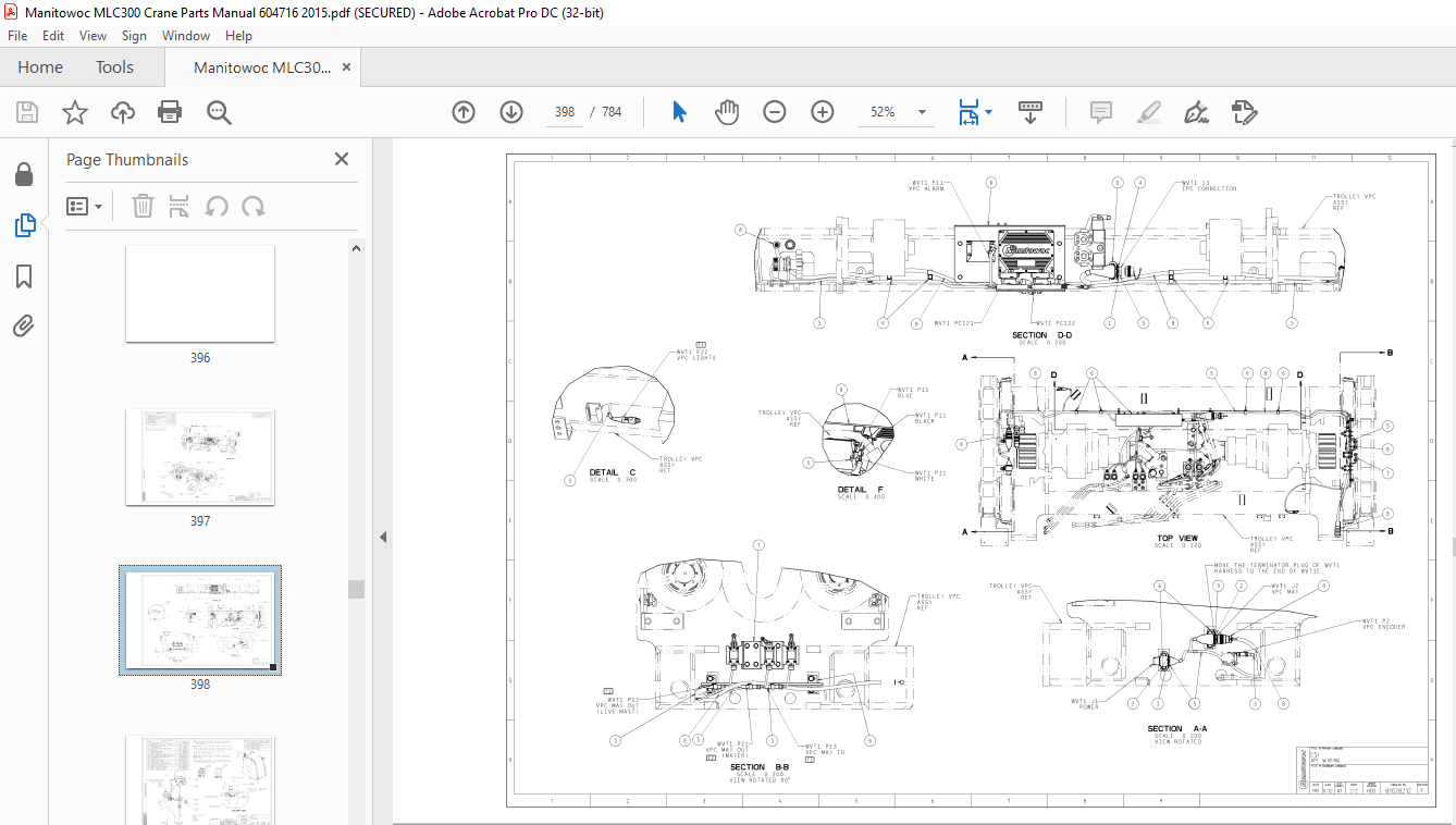
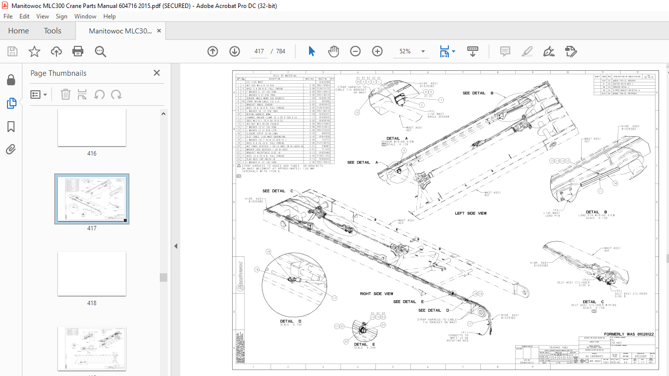
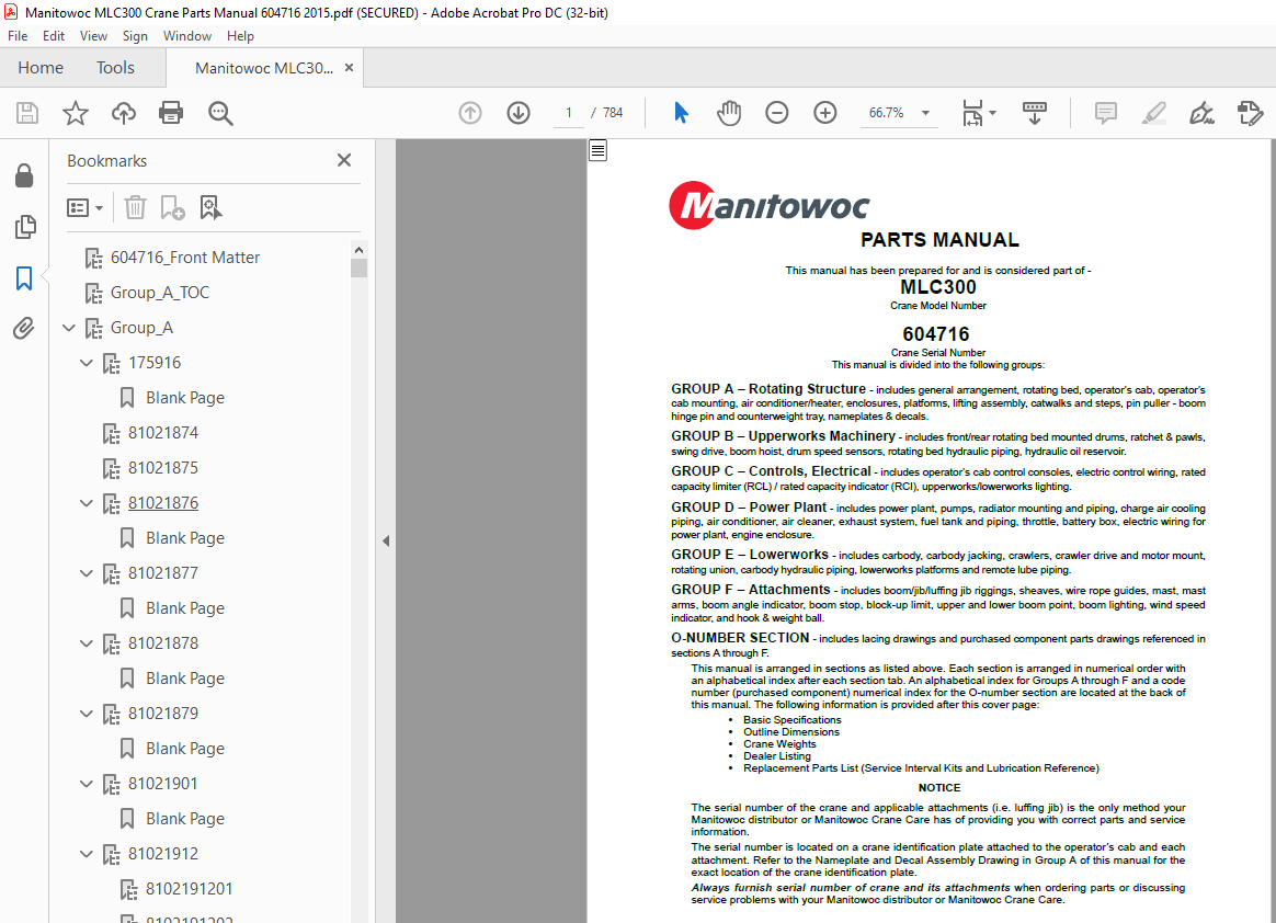
TABLE OF CONTENTS:
Manitowoc Crane MLC300 Parts Manual SN 604716 – PDF DOWNLOAD
GROUP A – Rotating Structure – includes general arrangement, rotating bed, operator’s cab, operator’s
cab mounting, air conditioner/heater, enclosures, platforms, lifting assembly, catwalks and steps, pin puller – boom
hinge pin and counterweight tray, nameplates & decals.
GROUP B – Upperworks Machinery – includes front/rear rotating bed mounted drums, ratchet & pawls,
swing drive, boom hoist, drum speed sensors, rotating bed hydraulic piping, hydraulic oil reservoir.
GROUP C – Controls, Electrical – includes operator’s cab control consoles, electric control wiring, rated
capacity limiter (RCL) / rated capacity indicator (RCI), upperworks/lowerworks lighting.
GROUP D – Power Plant – includes power plant, pumps, radiator mounting and piping, charge air cooling
piping, air conditioner, air cleaner, exhaust system, fuel tank and piping, throttle, battery box, electric wiring for
power plant, engine enclosure.
GROUP E – Lowerworks – includes carbody, carbody jacking, crawlers, crawler drive and motor mount,
rotating union, carbody hydraulic piping, lowerworks platforms and remote lube piping.
GROUP F – Attachments – includes boom/jib/luffing jib riggings, sheaves, wire rope guides, mast, mast
arms, boom angle indicator, boom stop, block-up limit, upper and lower boom point, boom lighting, wind speed
indicator, and hook & weight ball.
O-NUMBER SECTION – includes lacing drawings and purchased component parts drawings referenced in
sections A through F.
This manual is arranged in sections as listed above. Each section is arranged in numerical order with
an alphabetical index after each section tab. An alphabetical index for Groups A through F and a code
number (purchased component) numerical index for the O-number section are located at the back of
this manual. The following information is provided after this cover page:
• Basic Specifications
• Outline Dimensions
• Crane Weights
• Dealer Listing
• Replacement Parts List (Service Interval Kits and Lubrication Reference)
More products