$29
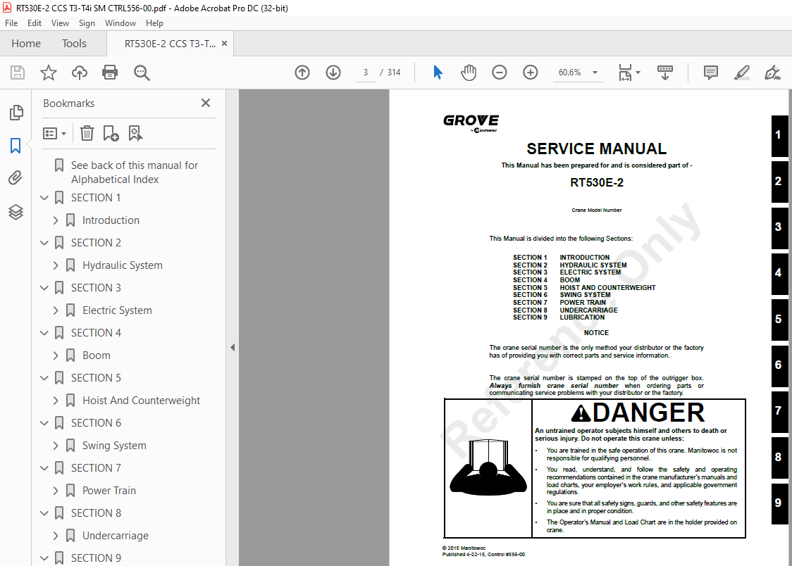
Manitowoc Grove RT530E-2 Service Manual – PDF DOWNLOAD
Manitowoc Grove RT530E-2 Service Manual – PDF DOWNLOAD
FILE DETAILS:
Manitowoc Grove RT530E-2 Service Manual – PDF DOWNLOAD
Language : English
Pages :314
Downloadable : Yes
File Type : PDF
TABLE OF CONTENTS:
Manitowoc Grove RT530E-2 Service Manual – PDF DOWNLOAD
See back of this manual for Alphabetical Index 5
SECTION 1 13
Introduction 13
Description 13
List of Specifications 14
General 14
Dimensions 14
Capacities 14
Torque Converter/Transmission 14
Engine 14
Cummins QSB67 14
Axles 14
Brakes 14
Wheels and Tires 14
Swing Gearbox 14
Boom 14
Swivel Assembly 14
Hydraulic Pumps 15
Pump #1 15
Pump #2 15
Pump #3 15
Hoists 15
General Maintenance 20
Cleanliness 20
Removal and Installation 20
Disassembly and Assembly 20
Pressing Parts 20
Locks 20
Wires and Cables 21
Shims 21
Bearings 21
Antifriction Bearings 21
Double Row, Tapered Roller 21
Heating Bearings 21
Installation 21
Preload 21
Sleeve Bearings 21
Gaskets 21
Batteries 21
Hydraulic Systems 22
Cleanliness 22
Keep the System Clean 22
Sealing Elements 22
Hydraulic Lines 22
Visual Inspection of Hoses and Fittings 22
Electrical System 23
Connectors, Harnesses, Wires, and Connectors 23
Fatigue of Welded Structures 23
Loctite 24
Application of Medium Strength Loctite 24
Primer Application 24
Adhesive/Sealant Application 24
Fasteners and Torque Values 24
Torque Wrenches 24
Torque Values 25
Weld Studs 28
Wire Rope 29
General 29
Environmental Conditions 29
Dynamic Shock Loads 29
Lubrication 29
Precautions and Recommendations During Inspection or Replacement 29
Wire Rope Inspection (Running Ropes and Pendant Cables) 30
Keeping Records 30
Frequent Inspection 30
Periodic Inspection 31
Wire Rope Inspection (Boom Extension and Retraction Cables) 31
Periodic Inspection 31
Wire Rope Inspection/Replacement (All Wire Rope) 31
Seizing Wire Rope 32
Method 1 32
Method 2 32
Installing 35×7 Class Wire Rope 33
Procedures for Cutting and Preparing 35×7 Class Wire Rope 33
SECTION 2 35
Hydraulic System 35
Description 36
Maintenance 39
Hydraulic Oil Recommendations 39
Draining and Flushing 39
Removing Air from the Hydraulic System 40
Parts Replacement 40
Directional Control Valves 40
Inspection 40
Valve Leakage 41
Binding Spools 41
Supply Pressure and Return Circuit 42
Description 42
Hydraulic Reservoir and Filter 42
Pump Distribution 42
Pump No 1 42
Pump No 2 42
Pump No 3 42
Maintenance 43
Troubleshooting 43
Return Hydraulic Filter Assembly 46
Element Removal 46
Element Installation 46
Hydraulic Reservoir Removal 46
Hydraulic Reservoir Installation 46
Oil Cooler 47
Description 47
Hydraulic Pumps 48
Description 48
Pump No 1 48
Pump No 2 48
Pump No 3 48
Maintenance 48
No 1 Pump Removal 48
No 1 Pump Installation 48
No 2 Pump Removal 48
No 2 Pump Installation 49
No 3 Pump Removal 49
No 3 Pump Installation 49
Testing After Rebuild or Replacement 49
Hydraulic Gear Pump Start-up Procedure 49
Piston Pump Start-up Procedure 50
Pressure Setting Procedures 51
Procedure A – For Checking/Setting The Main Control Valve For Hoists(s), Boom Lift and Piston Pump 53
Procedure B – For Setting The Outrigger/ Rear Steer/Oil Cooler Motor Pressures 53
Procedure C – For Checking/Setting The Swing Directional Control Valve Work Port Relief Valves 54
Procedure D – For Checking/Setting The Service Brake Dual Accumulator Charge Valve Charging Limits 54
Procedure E – For Checking/Pre-Charging The Service Brake Accumulators 54
Procedure F – For Checking/Setting the Front Steer Pressure 55
Procedure G – For Checking/Setting the Pilot Supply Pressure 55
Procedure H – For Checking/Setting The Swing Brake Release Pressure 55
Procedure J – For Setting Threshold on Electronic Controllers 55
Procedure K – Setting Threshold and Max on Swing Brake Pedal 56
Valves 61
General 61
Directional Control Valves 64
Description 64
Maintenance 64
Boom Lift/Telescope/Hoist Valve Bank Removal 64
Boom Lift/Telescope/Hoist Valve Bank Installation 64
Functional Check (All Valve Banks) 64
Function Check – RCL Lockout Valves 64
Accessory With Swing Directional Control Manifold 67
Description 67
Maintenance 67
Removal 67
Installation 67
Steering Control Valve 69
Description 69
Maintenance 69
Removal 69
Installation 69
Tandem Brake Valve with Treadle Pedal 70
Description 70
Maintenance 70
Removal 70
Installation 70
Dual Accumulator Charge Valve 71
Description 71
Maintenance 71
Removal 71
Installation 71
Hydraulic Accumulator Service Brake 73
Description 73
Maintenance 73
Removal 73
Installation 73
Servicing 73
Holding Valves 74
Description 74
Maintenance 74
Removal 74
Installation 74
Cross Axle Differential Lock Valve 75
Description 75
Maintenance 75
Removal 75
Installation 75
Outrigger Control Manifold 77
Description 77
Maintenance 77
Removal 77
Inspection 77
Installation 77
Functional Check 77
Pilot Operated Check Valve 78
Description 78
Maintenance 78
Removal 78
Installation 78
Integrated Outrigger/Rear Steer Manifold 79
Description 79
Maintenance 79
Removal 79
Installation 79
Check Valves 82
Description 82
Maintenance 82
Removal 82
Installation 82
Range Shift/Parking Brake Valve 83
Description 83
Maintenance 83
Removal 83
Installation 83
Functional Tests 83
Axle Oscillation Lockout Valve (Standard Units) 84
Description 84
Maintenance 84
Removal 84
Installation 84
Axle Oscillation Lockout Valve (Optional CE Units) 86
Description 86
Maintenance 86
Removal 86
Installation 86
Cylinders 88
General 88
Maintenance 88
General 88
Surface Protection for Cylinder Rods 88
Leakage Check 88
Temperature Effects on Hydraulic Cylinders 89
Lift Cylinder 91
Description 91
Maintenance 91
Disassembly 91
Inspection 91
Assembly 91
Dual Rod Telescope Cylinder 94
Description 94
Maintenance 94
Disassembly 94
Inspection 96
Assembly 96
Axle Oscillation Lockout Cylinder 98
Description 98
Maintenance 98
Disassembly 98
Inspection 98
Assembly101
Steer Cylinder102
Description102
Maintenance102
Disassembly102
Inspection102
Assembly102
Outrigger Extension Cylinder105
Description105
Maintenance105
Disassembly105
Inspection105
Assembly105
Outrigger jack Cylinder107
Description107
Maintenance107
Disassembly107
Inspection108
Assembly109
SECTION 3111
Electric System111
Description111
General111
Alternator111
Batteries111
Fuse Panel112
Relays113
Maintenance114
General114
General Troubleshooting114
Troubleshooting Swivel-Caused Electrical Problems114
Connector Troubleshooting114
Troubleshooting Engine Starting Problems115
Troubleshooting Engine Charging Problems115
Troubleshooting Accessories116
Alternator Replacement117
Removal117
Installation117
Check117
Starter Replacement117
Removal117
Installation117
Check117
Battery Replacement118
Removal118
Installation118
Relay Panel Component Replacement118
Accessory Relay118
Rocker Switch Replacement118
Removal118
Inspection119
Installation119
Check119
Ignition Switch Replacement119
Removal119
Inspection120
Installation120
Check120
Turn Signal Lever and Transmission Shift Lever Replacement120
Removal120
Installation120
Check121
Windshield Wiper Assembly Replacement122
Removal122
Inspection122
Installation122
Check123
Windshield Washer Assembly Replacement123
Removal123
Inspection123
Installation123
Check123
Skylight Wiper Assembly Replacement123
Removal123
Inspection123
Installation123
Check124
Appendix A: Crane Control System (CCS) Fault Codes126
Component Codes126
Condition Codes143
Device Codes146
Index Codes147
SECTION 4149
Boom149
Description149
Theory Of Operation149
Boom Extension149
Boom Retraction150
Maintenance154
Removal154
Boom Disassembly154
Remove the Base Section154
Disconnect Inner Mid Section156
Remove the Inner Mid Section157
Remove Outer Mid Section158
Remove Telescope Cylinder160
Boom Nose Sheaves161
Boom Assembly161
Install Telescope Cylinder161
Install Outer Mid Section162
Install Inner Mid Section164
Connect Inner Mid Section165
Install Base Section166
Boom Installation167
Functional Check167
Inspection167
Boom Alignment And Servicing167
Boom Extension And Retraction Cable168
Maintenance168
Inspection168
Extension Cable Adjustment168
Retract Cable Adjustment169
Telescope Circuit169
Description169
Theory Of Operation169
Maintenance170
Telescope Circuit Troubleshooting170
Removal And Installation172
Disassembly And Assembly172
Lift Circuit173
Description173
Theory Of Operation173
Maintenance173
Lift Circuit Troubleshooting173
Removal175
Disassembly And Assembly175
Installation175
Swingaway Boom Extension177
Description177
Maintenance177
Removal177
Installation181
Hook Block182
Description182
Maintenance182
Periodic Maintenance182
SECTION 5183
Hoist And Counterweight183
Description183
Theory of Operation183
Maintenance183
Warm-up Procedure183
Removal184
Installation185
Functional Check185
Servicing185
Fluid Level185
Usage and Inspection186
Preventative Maintenance186
Oil Sampling188
Oil Change188
Gear Oil Sampling and Analysis188
General Guidelines for Iron Contaminant Level188
Brake Test Procedure188
Hoist to Boom Alignment189
Preparation189
Tools Required189
Procedure190
Piston Motor and Control Valve191
Description191
Maintenance191
Removal191
Installation191
Description191
Maintenance191
Idler Drum191
Removal and Disassembly191
Cleaning and Inspection191
Assembly and Installation191
Cable Follower192
Removal and Disassembly192
Cleaning and Inspection192
Assembly and Installation192
Complete Assembly194
Removal194
Installation194
Hoist Drum Rotation Indicator System194
Description194
Maintenance194
General194
Rotation Sensor in Hydraulic Motor194
Thumb Thumper Solenoid194
Counterweight Removal196
Fixed Counterweight Description196
Fixed Counterweight Removal196
Fixed Counterweight Installation196
SECTION 6199
Swing System199
Introduction199
Description199
Theory of Operation199
Swing Drive199
Maintenance201
Troubleshooting201
Swing Motor204
Description204
Maintenance204
Removal204
Installation204
Test204
Swing Gearbox And Brake205
Description205
Maintenance205
Swing Brake205
Removal205
Installation205
Gearbox205
Removal205
Installation205
Servicing206
Checking The Oil Level206
Testing206
Swing Bearing207
Description207
Maintenance207
General207
Torquing Turntable Bolts207
General207
Torque Values208
Tools Required208
Inner Race Torquing208
Outer Race Torquing208
Removal209
Inspection210
Installation210
Testing211
Swivels212
Description212
Hydraulic Swivel214
Description214
Theory of Operation214
Maintenance214
Removal214
Installation215
Electrical Swivel216
Description216
Theory of Operation216
Maintenance216
Removal216
Installation216
Preventive Maintenance217
Slew Potentiometer Adjustment217
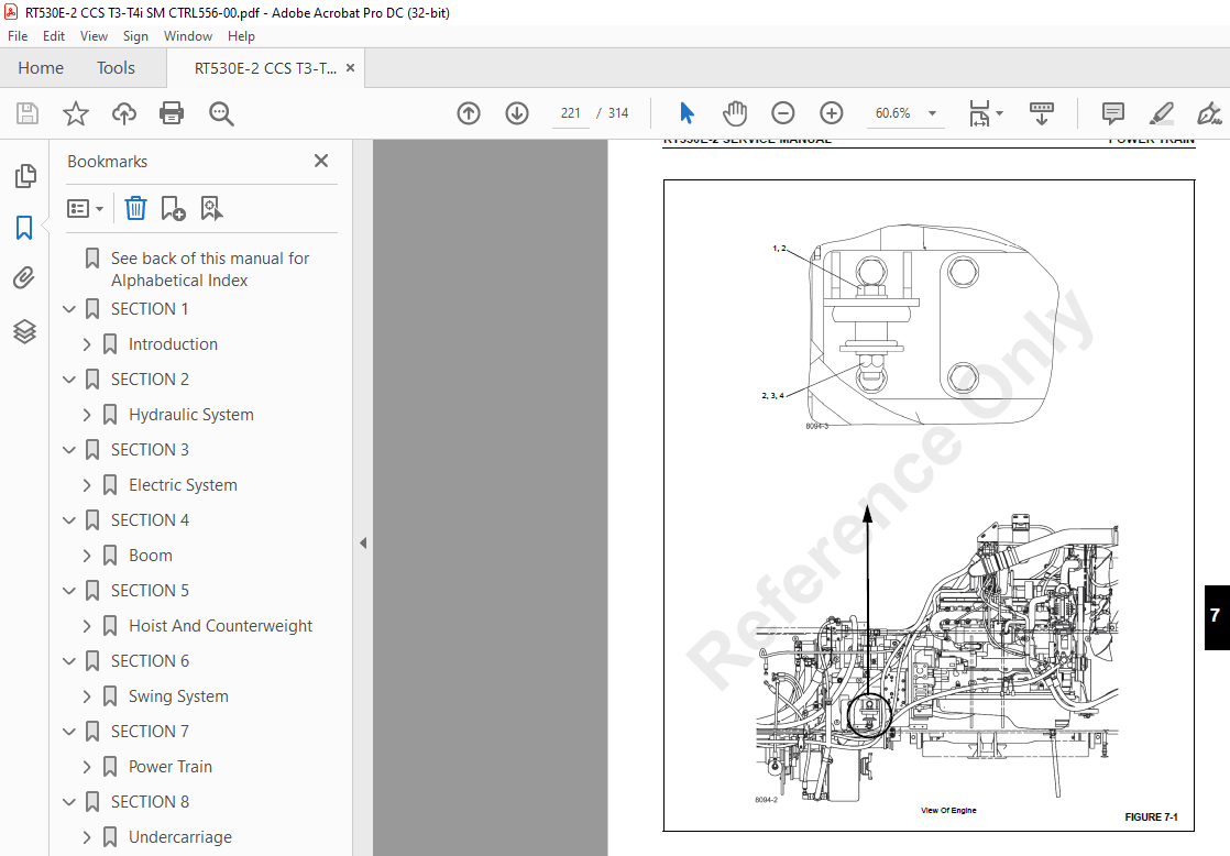
SECTION 7219
Power Train219
Engine219
Description219
Maintenance220
Engine Removal220
Engine Installation223
Engine Drive Belts224
Fuel System225
Description225
Fuel Tank225
Injection Fuel Pump225
Fuel Filter-Water Separator225
Electric Lift Pump225
Maintenance225
Fuel Tank225
Removal225
Installation225
Fuel Filter-Water Separator225
Draining225
Air Intake and Exhaust System227
Description227
Air Intake227
Air Cleaner Checks227
Check For Filter Restriction227
Filter Element Replacement229
Element Cleaning229
Air Cleaner Body229
Precleaner229
Vacuator Valve230
Duct Work230
Charge-Air Cooler System231
Maintenance231
Muffler and Diesel Oxidation Catalyst – Tier 4 Interim232
Removal232
Installation232
Slip Joint Exhaust Connectors232
After 1000 Hours, or One Year232
2000 Hours or 2 Years232
4000 Hours or 4 Years232
5000 Hours or 5 Years232
Water Cooling System234
Description234
Maintenance234
General234
Effects of Cooling System Neglect234
Overheating234
Overcooling234
Antifreeze/Coolant234
Rust Prevention234
Engine Antifreeze/Coolant Fill Procedure (when level is low)235
Antifreeze/Supplemental Coolant Additives Maintenance Summary235
Cooling System Level Check Interval235
SCA Level Check/Coolant Filter Change Interval235
Cleaning235
Pressure Flushing236
Component Inspection236
Radiator/Surge Tank236
Engine Water Jacket236
Water Pump237
Fans and Belts237
Thermostat237
Hoses and Clamps237
Test Equipment237
Antifreeze/Coolant237
Radiator Removal and Installation237
Removal237
Installation238
Drive Train239
Description239
Maintenance239
Drive Lines239
Removal239
Installation239
Lubrication239
Transmission/Torque Converter239
Description239
Theory of Operation239
Maintenance240
General Information240
Troubleshooting240
Hydraulic Checks240
Troubleshooting Procedures241
Removal241
Installation241
Servicing the Crane After Transmission/ Torque Converter Overhaul243
Lubrication244
Type Of Oil244
Capacity244
Check Period244
Normal Drain Period244
SECTION 8245
Undercarriage245
Axles245
Description245
Maintenance246
Removal246
Cleaning249
Installation249
Wheel Alignment Check Procedure249
Rear Steer Indicator Adjustment Procedure249
Wheels and Tires251
Description251
Maintenance251
Mounting Wheel Assemblies251
Steering Systems252
Description252
Front Steering System252
Rear Steering System252
Theory of Operation252
Front Steering System252
Rear Steering System252
Maintenance253
Front Steering System253
Troubleshooting253
Functional Check254
Rear Steering System254
Troubleshooting254
Hydraulic Pumps255
Description255
Front Steer255
Rear Steer255
Front Steering Control Valve255
Description255
Maintenance255
Removal255
Installation255
Integrated Outrigger/Rear Steer Manifold255
Maintenance255
Removal255
Installation256
Steer Cylinders256
Description256
Maintenance256
Removal256
Installation256
Rear Axle Oscillation Lockout System257
Description257
Axle Oscillation Lockout Cylinders257
Description257
Maintenance257
Removal257
Installation257
Brake System258
Description258
Service Brakes258
Parking Brake258
Theory of Operation258
Service Brakes258
Parking Brake258
Maintenance259
Troubleshooting259
General259
Bleeding the Brake System259
Pressure Bleeding the Brake System260
Manually Bleeding the Brake System260
Service Brakes260
Description260
Maintenance260
Removal260
Linings260
Caliper261
Disassembly261
Caliper261
Inspection262
Periodic On-Vehicle262
Shoes, Linings, and End Plates262
Caliper for Leaks262
Dust Seals263
Disc263
Caliper Parts263
Cleaning264
Corrosion Protection264
Assembly264
Caliper264
Installation265
Linings265
Caliper266
Parking Brake Actuator266
Description266
Maintenance266
Removal266
Installation266
Adjustment267
Parking Brake267
Description267
Maintenance267
Removal267
Installation267
Park Brake Valve268
Description268
Removal268
Installation268
Functional Tests268
Outriggers268
Outrigger Circuit268
Description268
Theory of Operation268
Maintenance269
Troubleshooting269
Outrigger Beam272
Description272
Theory of Operation272
Maintenance272
Removal272
Inspection275
Installation275
Wear Pad Adjustment275
Extension Cylinder276
Description276
Maintenance276
Removal276
Installation277
Functional Check277
Jack Cylinder277
Description277
Maintenance277
Removal277
Installation277
Functional Check278
Outrigger Jack Cylinder Internal Leak Test278
Checking Cylinder For Internal Piston Seal Leak278
Testing Pilot Operated Check Valve For Leakage278
Outrigger Control Valves279
Description279
Pilot Operated Check Valve279
Integrated Outrigger/Rear Steer Manifold279
Outrigger Control Manifold279
SECTION 9281
Lubrication281
General281
Lubrication Intervals281
Arctic Conditions Below -18°C (0°F)281
Arctic Conditions Down To -40° C (-40°F)281
ALL Weather Package & Lubricants281
Standard Lubricants Package282
Surface Protection For Cylinder Rods282
Wire Rope Lubrication282
Lubrication Points283
CraneLUBE283
Safety283
Steering and Suspension284
Axles286
Drive Train288
Drive Train (continued)290
Outriggers292
Turntable294
Boom296
Boom (continued)298
Hoist300
Hydraulic302
Carwell® Rust Inhibitor304
Protecting Cranes From Rusting304
Cleaning Procedures304
Inspection and Repair305
Application305
Areas of Application305
IMAGES PREVIEW OF THE MANUAL:
More products