$39
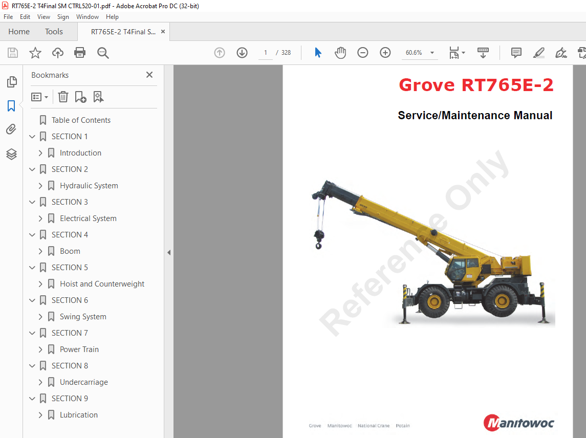
Manitowoc Grove RT765E-2 Service Manual – PDF DOWNLOAD
Manitowoc Grove RT765E-2 Service Manual – PDF DOWNLOAD
FILE DETAILS:
Manitowoc Grove RT765E-2 Service Manual – PDF DOWNLOAD
Language : English
Pages :328
Downloadable : Yes
File Type : PDF
TABLE OF CONTENTS:
Manitowoc Grove RT765E-2 Service Manual – PDF DOWNLOAD
Table of Contents 5
SECTION 1 13
Introduction 13
General 13
Overview of Manuals 13
Customer Support 14
General Crane Design 14
Specific Crane Description 14
Lifting Capacities (Load Chart) 14
Basic Components 14
Axle Weight Distribution 14
Serial Number Location 14
Transportation and Lifting Data 14
List Of Specifications 15
General 15
Dimensions 15
Capacities 15
Torque Converter 15
Transmission 15
Engine 15
Cummins QSB 67 15
Axles 15
Brakes 15
Wheels and Tires 15
Swing Gearbox 15
Boom 15
Swivel Assembly 15
Hydraulic Pumps 15
Pump #1 15
Pump #2 15
Pump #3 15
Hoists 16
Crane Nomenclature 19
General Maintenance 21
Cleanliness 21
After Cleaning 21
Removal and Installation 21
Disassembly and Assembly 21
Pressing Parts 22
Locking Devices 22
Wires and Cables 22
Shims 22
Hoses and Tubes 22
Inspection 22
Installation 23
Bearings 23
Antifriction Bearings 23
Double Row, Tapered Roller 23
Heating Bearings 23
Installation 23
Preload 23
Sleeve Bearings 23
Gaskets 23
Batteries 23
Hydraulic Systems 24
Cleanliness 24
Keep the System Clean 24
Sealing Elements 24
Hydraulic Lines 24
Visual Inspection of Hoses and Fittings 24
Hydraulic Fittings 25
Flats from Finger Tight (FFFT) Method 25
37° Flared Steel Fitting: Tube or Hose to Fitting 25
Adjustable Straight Thread O-ring Fittings 25
Nonadjustable Straight Thread O-ring Fitting: Fitting to Port 26
Electrical System 26
Harnesses, Wires, and Connectors 26
Fatigue of Welded Structures 27
Loctite® 27
Application of Medium Strength Loctite® 27
Primer Application 27
Adhesive/Sealant Application 27
Fasteners and Torque Values 28
Torque Wrenches 28
Torque Values 28
Weld Studs 31
Wire Rope 32
General 32
Environmental Conditions 32
Dynamic Shock Loads 32
Lubrication 32
Precautions and Recommendations During Inspection or Replacement 32
Wire Rope Inspection (Running Ropes and Pendant Cables) 33
Keeping Records 33
Frequent Inspection 33
Periodic Inspection 34
Wire Rope Inspection (Boom Extension and Retraction Cables) 34
Periodic Inspection 34
Wire Rope Inspection/Replacement (All Wire Rope) 34
Seizing Wire Rope 35
Method 1 35
Method 2 35
Installing 35×7 Class Wire Rope 36
Procedures for Cutting and Preparing 35×7 Class Wire Rope 36
SECTION 2 39
Hydraulic System 39
Description 40
Hydraulic Symbols 41
Maintenance 43
Preparation 43
Hydraulic System Maintenance Precautions 43
Label Parts when Disassembling 43
Hydraulic Oil Recommendations 43
Draining and Flushing 43
Removing Air from the Hydraulic System 44
Parts Replacement 45
Directional Control Valves 45
Inspection 45
Valve Leakage 45
Binding Spools 45
Visual Inspection of Hoses and Fittings 46
Supply Pressure and Return Circuit 47
Description 47
Hydraulic Reservoir and Filter 47
Pump Distribution 48
No 1 Pump 48
No 2 Pump 48
No 3 Pump 48
Troubleshooting 48
Symptoms and Solutions 48
Troubleshooting Aids 50
Troubleshooting Procedures 50
Hydraulic Oil Return Filter Assembly 51
Element Removal 51
Element Installation 51
Fill Cap/Breather 51
Removal and Replacement 51
Oil Cooler 53
Description 53
Oil Temperature Switches 53
Hydraulic Pumps 55
Description 55
Pump No 1 55
Pump No 2 55
Pump No 3 55
Maintenance 55
No 1 Pump Removal 55
No 1 Pump Installation 55
No 1 Pump and Pump Disconnect Assembly Removal (Optional) 55
No 1 Pump and Pump Disconnect Assembly Installation (Optional) 56
No 2 Pump Removal 56
No 2 Pump Installation 56
No 3 Pump Removal 57
No 3 Pump Installation 57
Testing after Repair or Replacement 57
Pressure Setting Procedures 60
Procedure A – Main Control Valve Reliefs 61
Procedure B – Main Directional Control Valve Pilot Supply Pressure 62
Procedure C – Swing Brake Pilot Supply Pressure 62
Procedure D – Brake Charge Supply Valve Relief Pressure 62
Procedure E – Charge Air Cooler Valve Relief Pressure 63
Procedure F – Brake Dual Accumulator Charge Valve Pressure Limits 63
Procedure G – Accumulator Pre-Charge Pressure 63
Procedure H – PreCharging the Accumulator 64
Procedure I – Swing Valve Work Port Reliefs Pressure 64
Procedure J – Front Steer Relief Valve Pressure 65
Procedure K – Outrigger/Rear Steer Valve Relief 65
Procedure L – Hydraulic Oil Cooler Fan Motor Control Valve 65
Procedure M – Counterweight Removal Valve 66
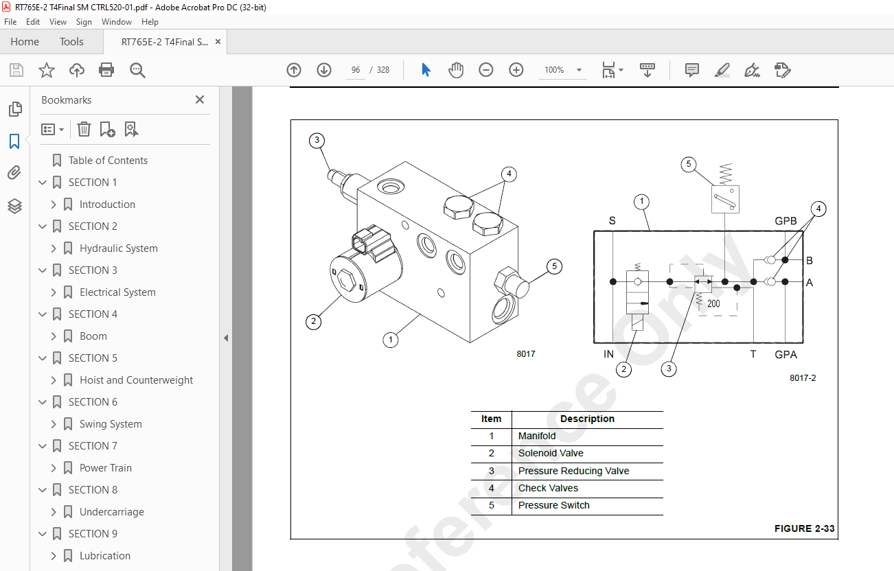
Valves 67
General 67
Directional Control Valves 70
Description 70
Lift/Telescope/Hoist Directional Valve 70
Swing/Steer Directional Valve 70
Counterweight Removal Directional Valve (Optional) 70
Maintenance 70
Swing/Steer Directional Valve Removal 70
Swing/Steer Directional Valve Installation 70
Hoist/Lift/Telescope Directional Valve Removal 70
Hoist/Lift/Telescope Directional Valve Installation 70
Counterweight Removal Directional Valve Removal 70
Counterweight Removal Directional Valve Installation 70
Functional Check (All Directional Valves) 70
Hydraulic Remote Control Valve 75
Description 75
Dual Axis Controllers (CE Units) 75
Maintenance 75
Armrest Control Valve Removal 75
Armrest Control Valve Installation 75
Armrest Control Valve Functional Check 75
Telescope Pedal Control Valve Removal (With Auxiliary Hoist Option) 75
Telescope Pedal Control Valve Installation (With Auxiliary Hoist Option) 75
Telescope Pedal Control Valve Functional Check (With Auxiliary Hoist Option) 75
Dual Accumulator Charge Valve 78
Description 78
Maintenance 78
Removal 78
Installation 78
Swing Brake And Armrest Lockout Valve Manifold 80
Description 80
Maintenance 80
Removal 80
Installation 80
Function Check – Swing Brake Release Valve 80
Function Check – Crane Function Valve 80
Inlet Filter Screen Replacement 80
Holding Valve 82
Description 82
Maintenance 82
Removal 82
Installation 82
Test the holding valve and port block or manifold by operating the lift cylinder and/or the telescope cylinder, as applicable Verify lift cylinder and/or telescope cylinder works without problems; verify there is no leaking Make repairs as needed 82
Boom Lock Valve 82
Description 82
Outrigger/Rear Steer Valve 84
Description 84
Maintenance 85
Removal 85
Installation 85
Functional Check 85
Outrigger Control Manifold 86
Description 86
Maintenance 87
Removal 87
Inspection 87
Installation 87
Functional Check 87
Parking Brake/Range Shift Valve 88
Description 88
Maintenance 88
Removal 88
Installation 88
Functional Tests 88
Axle Oscillation Lockout Valve 90
Description 90
Maintenance 90
Removal 90
Installation 90
High Speed Boost Selector Valve 91
Description 91
Maintenance 91
Removal 91
Installation 91
Hydraulic Accumulator 92
Description 92
Maintenance 92
Removal 92
Installation 92
Servicing 92
Service Brake and CAC Fan Motor Priority Flow Control Valve 93
Description 93
Maintenance 93
Removal 93
Installation 93
Oil Cooler Fan Motor Priority Flow Control Valve 94
Description 94
Maintenance 94
Removal 94
Installation 94
Telescope Cylinder Charge Valve Manifold (If Equipped) 95
Description 95
Maintenance 95
Removal 95
Installation 95
Cylinders 98
General 98
Maintenance 98
General 98
Surface Protection For Cylinder Rods 98
Leakage Check 98
Temperature Effects On Hydraulic Cylinders 99
Lift Cylinder101
Description101
Maintenance101
Disassembly101
Inspection101
Assembly103
Lower Telescope Cylinder105
Description105
Maintenance105
Disassembly105
Inspection105
Assembly105
Upper Telescope Cylinder109
Description109
Maintenance109
Disassembly109
Inspection109
Assembly109
Axle Oscillation Lockout Cylinder112
Description112
Maintenance112
Disassembly112
Inspection112
Assembly114
Steer Cylinder115
Description115
Maintenance115
Disassembly115
Inspection115
Assembly117
Outrigger Extension Cylinder118
Description118
Maintenance118
Disassembly118
Inspection118
Assembly120
Outrigger Stabilizer Cylinder121
Description121
Maintenance121
Disassembly121
Inspection121
Assembly123
Test123
Counterweight Removal Cylinder124
Description124
Maintenance124
Disassembly124
Inspection124
Assembly124
SECTION 3127
Electrical System127
Description127
General127
Alternator129
Batteries129
Cab Electrical Panel129
Carrier Electrical Panel131
Maintenance133
General133
Visual Inspection and Replacement of Electrical Harnesses and Cables133
General Troubleshooting134
Troubleshooting Swivel-Caused Electrical Problems134
Connector Troubleshooting134
Alternator/Charging System Troubleshooting135
Required Tools135
Visual Check135
Engine Off Tests136
Batteries136
Voltage at Alternator136
Battery Drain136
Engine On Tests136
Output Voltage Test136
Maximum Amperage Test136
Voltage Drop Test136
Alternator Replacement137
Removal137
Installation137
Check137
Starter Replacement137
Removal137
Installation137
Check137
Battery Replacement138
Removal138
Installation138
Relay Panel Component Replacement138
Accessory Relay138
Buzzer Replacement138
Gauge Cluster Replacement138
Removal139
Installation139
Check139
Rocker Switch Replacement139
Removal139
Inspection139
Installation140
Check140
Ignition Switch Replacement140
Removal140
Inspection140
Installation140
Check141
Turn Signal Lever and Transmission Shift Lever Replacement141
Removal141
Installation141
Check142
Windshield Wiper Assembly Replacement143
Removal143
Inspection143
Installation143
Check144
Windshield Washer Assembly Replacement144
Removal144
Inspection144
Installation144
Check144
Skylight Wiper Assembly Replacement144
Removal144
Inspection144
Installation144
Check145
Telescope Cylinder Charge System – Electrical Schematic (If Equipped)146
Tools for Troubleshooting147
Optional Equipment147
Beacon Light147
Boom Mounted Floodlights147
Rear View Mirror147
Air Conditioner147
Cold Weather Operation147
Component Coolant Heater147
Troubleshooting148
Maintenance Instructions148
SECTION 4149
Boom149
Description149
Theory of Operation149
Boom Extension149
Boom Retraction150
Maintenance150
Removal150
Disassembly155
Boom Nose Sheaves157
Removal157
Installation158
Assembly158
Installation161
Functional Check162
Inspection162
Boom Alignment and Servicing162
Cam Operated Check Valve Adjustment163
Guide Block Adjustment163
Boom Extension and Retraction Cable164
Maintenance164
Inspection164
Adjustment164
Telescope Circuit165
Description165
Theory of Operation165
Maintenance166
Troubleshooting166
Removal and Installation168
Disassembly and Assembly168
Description168
Theory of Operation168
Maintenance168
Lift Cylinder Removal170
Disassembly and Assembly170
Lift Cylinder Installation170
Swingaway Boom Extension172
Description172
Maintenance172
Removal172
Installation178
Boom Extension Alignment Device Adjustment179
Swingaway Mounting Adjustment180
Description180
Maintenance180
Periodic Maintenance180
SECTION 5181
Hoist and Counterweight181
Description181
Theory of Operation181
Maintenance182
Warm-up Procedure182
Hoist Area Access182
Removal184
Installation184
Functional Check184
Fluid Level184
Usage and Inspection185
Preventative Maintenance185
Oil Sampling187
Oil Change187
Gear Oil Sampling and Analysis187
General Guidelines for Iron Contaminant Level187
Brake Test Procedure187
Hoist To Boom Alignment188
Preparation188
Tools Required188
Procedure188
Motor And Brake190
Description190
Maintenance190
Removal190
Installation190
Idler Drum And Cable Follower191
Description191
Maintenance191
Idler Drum191
Removal and Disassembly191
Cleaning and Inspection191
Assembly and Installation191
Cable Follower191
Removal and Disassembly191
Cleaning and Inspection191
Assembly and Installation191
Complete Assembly193
Removal193
Installation193
Third Wrap Indicator (Optional— Standard on CE)194
Description194
Maintenance194
Hoist Drum Rotation Indicator System195
Description195
Maintenance195
General195
Troubleshooting195
Removal195
Installation195
Hoist Control Valves197
Description197
Hydraulic Hoist Motor Control Valve197
Hoist Directional Control Valve197
Fixed Counterweight198
Description198
Maintenance198
Removal198
Installation198
Counterweight Plate198
Removable Counterweight (Optional)200
Removal200
Installation200
SECTION 6203
Swing System203
Description203
Theory of Operation203
Swing Drive203
Swing Brake203
Maintenance205
Swing Motor209
Description209
Maintenance209
Removal209
Installation209
Test209
Swing Gearbox And Brake210
Description210
Maintenance210
Swing Brake210
Removal210
Installation210
Testing210
Gearbox210
Removal210
Installation210
Servicing211
Checking The Oil Level211
Testing211
Swing Bearing212
Description212
Maintenance212
General212
Torquing Turntable Bolts212
General212
Tools Required213
Inner Race Torquing213
Outer Race Torquing213
Removal213
Inspection215
Installation215
Testing216
Swivels217
Description217
Hydraulic Swivel219
Description219
Theory Of Operation219
Maintenance219
Removal219
Installation220
Two Port Water Swivel221
Description221
Maintenance221
Removal221
Disassembly221
Cleaning And Inspection221
Assembly221
Installation221
Electrical Swivel222
Description222
Theory of Operation222
Maintenance222
Removal222
Installation222
Preventive Maintenance223
Slew Angle Zero Adjustment Procedure223
Slew Angle Verification223
Swing Lock Pin224
Description224
Maintenance224
360° Swing Lock Control (Positive Lock Type) (Optional)224
Description224
Maintenance224
SECTION 7225
Power Train225
Engine225
Description225
Maintenance226
Engine Removal226
Engine Installation226
Engine Drive Belts227
Electronic Control System228
Description228
Engine Control System Switches and Indicator Lights228
Engine Diagnostic/Speed Control Switch228
Increment/Decrement Switch228
Engine Stop Light228
Engine Warning Light228
Exhaust System Cleaning Indicator (Tier 4 Final Engines Only)228
Exhaust System Cleaning Switch (Tier 4 Final Engines Only)229
Inhibit Exhaust System Cleaning Indicator230
High Exhaust System Temperature230
Fuel System231
Description231
Fuel Tank231
Injection Fuel Pump231
Fuel Filter-water Separator231
Maintenance231
Fuel Tank231
Removal231
Installation231
Fuel Filter-Water Separator231
Draining231
Air Intake and Exhaust System233
Description233
Air Intake233
Air Cleaner Checks233
Check For Filter Restriction233
Filter Element Replacement235
Element Cleaning235
Air Cleaner Body235
Precleaner235
Vacuator Valve235
Duct Work236
Charge-Air Cooler System237
Maintenance237
Muffler238
Removal238
Installation238
Slip Joint Exhaust Connectors238
After 1000 Hours, or One Year238
2000 Hours or 2 Years238
4000 Hours or 4 Years238
5000 Hours or 5 Years238
Water Cooling System241
Description241
Maintenance241
General241
Effects of Cooling System Neglect241
Overheating241
Overcooling241
Antifreeze/Coolant241
Rust Prevention241
Engine Antifreeze/Coolant Fill Procedure (when level is low)241
Antifreeze/Supplemental Coolant Additives Maintenance Summary242
Cooling System Level Check Interval242
SCA Level Check Interval242
Cleaning242
Pressure Flushing242
Component Inspection243
Radiator/Surge Tank243
Engine Water Jacket243
Water Pump243
Fans and Belts243
Thermostat243
Hoses and Clamps244
Drive Train246
Description246
Maintenance246
Transmission246
Drive Shafts247
Removal247
Installation247
Lubrication247
Transmission/torque Converter248
Description248
Theory of Operation248
Maintenance249
General Information249
Troubleshooting249
Hydraulic Checks249
Troubleshooting Procedures249
Removal250
Installation250
Servicing the Crane after Transmission/Torque Converter Overhaul252
Lubrication252
Type of Oil and Capacities252
Normal Drain Period252
Towing or Pushing252
SECTION 8253
Undercarriage253
Axles253
Description253
Maintenance254
Removal254
Cleaning254
Installation254
Wheel Alignment Check Procedure255
Rear Steer Indicator Adjustment Procedure255
Wheels and Tires256
Description256
Maintenance256
Mounting Wheel Assemblies256
Typical Wear Patterns256
Incorrect Tire Pressure256
Incorrect Camber257
Incorrect Toe and Axle Alignment257
Incorrect Caster and Wheel Imbalance257
Cuts in the Tire Tread258
Spot Wear258
Feathered Edges258
Cupping258
Steering Systems259
Description259
Front Steering System259
Rear Steering System259
Secondary Steering System (CE Units)259
Theory of Operation259
Front Steering System259
Rear Steering System259
Secondary Steering System (CE Units)259
Maintenance260
Front Steering System260
Troubleshooting260
Functional Check260
Secondary Steering System261
Rear Steering System261
Troubleshooting261
Hydraulic Pumps262
Description262
Front Steer262
Rear Steer262
Front Steering Control Valve262
Description262
Maintenance262
Removal262
Installation262
Integrated Outrigger/Rear Steer Control Valve262
Description262
Maintenance262
Functional Check262
Steer Cylinders262
Description262
Maintenance262
Removal263
Installation263
Rear Axle Oscillation Lockout System263
Description263
Theory of Operation263
Axle Oscillation Lockout Cylinders265
Description265
Maintenance265
Removal265
Installation265
Axle Oscillation Lockout Valve265
Description265
When the axle oscillation solenoid valves are energized and open, hydraulic oil is allowed in and out of the cylinders, allowing them to oscillate265
Maintenance265
Brake System265
Description265
Service Brakes265
Parking Brake266
Theory of Operation266
Service Brakes266
Parking Brake266
Maintenance267
Troubleshooting267
General267
Bleeding the Brake System267
Pressure Bleeding The Brake System268
Manually Bleeding the Brake System268
Service Brakes268
Description268
Maintenance268
Removal268
Linings268
Caliper269
Disassembly269
Caliper269
Inspection270
Periodic On-Vehicle270
Shoes, Linings, and End Plates270
Caliper for Leaks270
Dust Seals271
Disc271
Caliper Parts271
Cleaning272
Corrosion Protection272
Assembly272
Caliper272
Installation273
Linings273
Caliper274
Parking Brake Actuator274
Description274
Maintenance274
Removal274
Installation274
Adjustment274
Parking Brake275
Description275
Maintenance275
Removal275
Installation275
Park Brake Solenoid Valve278
Description278
Maintenance278
Removal278
Installation278
Outrigger278
Outrigger Circuit278
Description278
Theory Of Operation278
Maintenance279
Troubleshooting279
Outrigger Beam282
Description282
Theory Of Operation282
Maintenance282
Removal282
Inspection283
Installation283
Wear Pad Adjustment283
Extension Cylinder286
Description286
Maintenance286
Removal286
Installation286
Functional Check286
Outrigger Monitoring System (Optional— Standard in North America)286
Description286
Removal286
Installation287
Stabilizer Cylinder287
Description287
Maintenance287
Removal287
Installation287
Functional Check288
Outrigger Control Valves288
Description288
Pilot Operated Check Valve288
Integrated Outrigger/Rear Steer Valve288
Outrigger Control Manifold288
SECTION 9289
Lubrication289
General289
Environmental Protection289
Lubricants and Lubrication Intervals289
Standard Lubricants289
Arctic Lubricants and Conditions291
Temperatures Below -9°C (15°F)291
Cold Weather Package and Lubricants291
Surface Protection for Cylinder Rods294
Wire Rope Lubrication294
lubrication Points295
CraneLUBE295
Safety295
Steering and Suspension296
Axles298
Drive Train300
Drive Train (continued)302
Turntable304
Outriggers306
Boom308
Boom (continued)310
Boom (continued)312
Hoist314
Hydraulic316
Carwell® Rust Inhibitor319
Protecting Cranes From Rusting319
Cleaning Procedures319
Inspection and Repair320
Application320
Areas of Application320
IMAGES PREVIEW OF THE MANUAL:
More products