$39
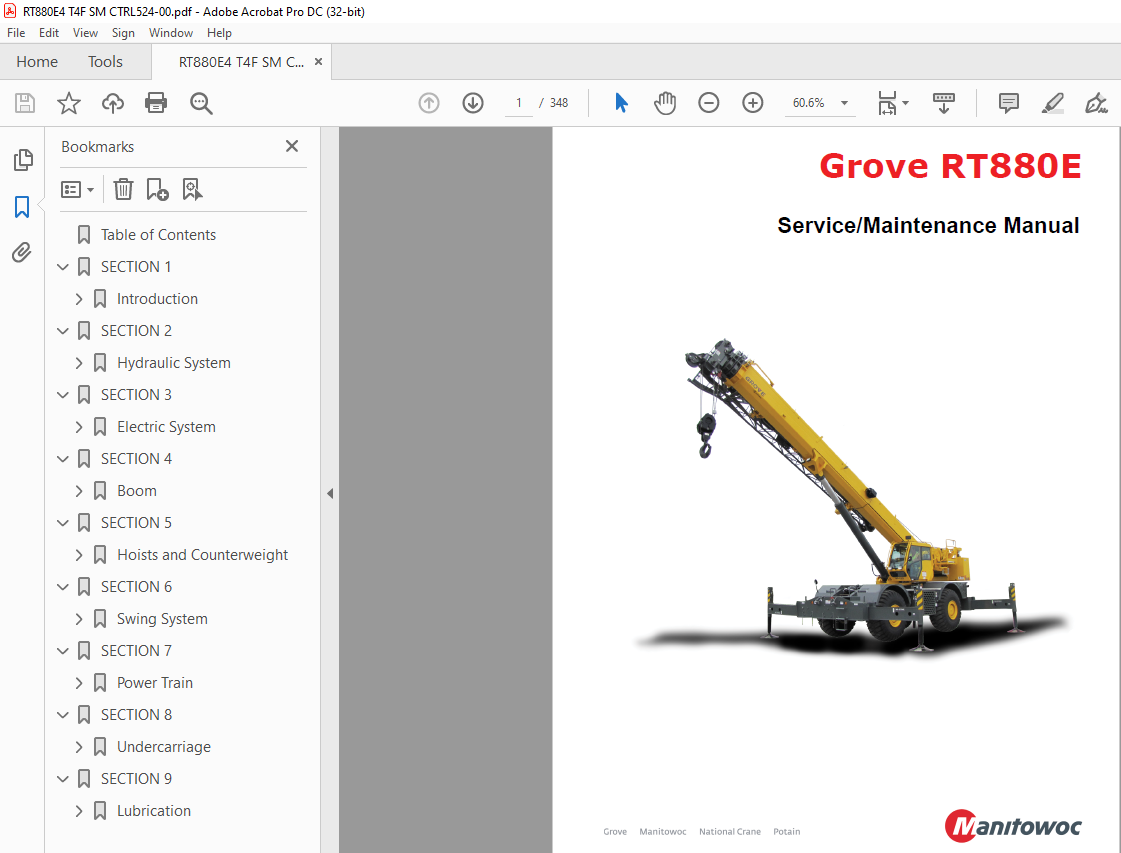
Manitowoc Grove RT880E SERVICE Manual – PDF DOWNLOAD
Manitowoc Grove RT880E SERVICE Manual – PDF DOWNLOAD
FILE DETAILS:
Manitowoc Grove RT880E SERVICE Manual – PDF DOWNLOAD
Language : English
Pages :348
Downloadable : Yes
File Type : PDF
TABLE OF CONTENTS:
Manitowoc Grove RT880E SERVICE Manual – PDF DOWNLOAD
Table of Contents 5
SECTION 1 13
Introduction 13
General 13
Overview of Manuals 13
Customer Support 14
General Crane Design 14
Specific Crane Description 14
Lifting Capacities (Load Chart) 14
Basic Components 14
Axle Weight Distribution 14
Serial Number Location 14
Transportation and Lifting Data 14
List of Specifications 15
General 15
Dimensions 15
Capacities 15
Torque Converter/Transmission 15
Engine 15
Cummins QSB67 15
Axles 15
Brakes 15
Wheels and Tires 15
Swing Gearbox 15
Boom 15
Swivel Assembly 15
Hydraulic Pumps 16
Pump #1 16
Pump #2 16
Hoists 16
General Maintenance 21
Cleanliness 21
Removal and Installation 21
Disassembly and Assembly 21
Pressing Parts 21
Locks 21
Wires and Cables 22
Shims 22
Hoses and Tubes 22
Inspection 22
Installation 22
Bearings 22
Antifriction Bearings 22
Double Row, Tapered Roller 23
Heating Bearings 23
Installation 23
Preload 23
Sleeve Bearings 23
Gaskets 23
Batteries 23
Hydraulic Systems 23
Cleanliness 23
Keep the System Clean 23
Sealing Elements 23
Hydraulic Lines 24
Visual Inspection of Hoses and Fittings 24
Hydraulic Fittings 25
Flats from Finger Tight (FFFT) Method 25
37° Flared Steel Fitting: Tube or Hose to Fitting 25
Adjustable Straight Thread O-ring Fittings 25
Nonadjustable Straight Thread O-ring Fitting: Fitting to Port 26
Electrical System 26
Harnesses, Wires, and Connectors 26
Fatigue of Welded Structures 26
Loctite® 27
Application of Medium Strength Loctite 27
Primer Application 27
Adhesive/Sealant Application 27
Fasteners and Torque Values 27
Torque Wrenches 28
Torque Values 28
Weld Studs 31
Wire Rope 32
General 32
Environmental Conditions 32
Dynamic Shock Loads 32
Lubrication 32
Precautions and Recommendations During Inspection or Replacement 32
Wire Rope Inspection (Running Ropes and Pendant Cables) 33
Keeping Records 33
Frequent Inspection 33
Periodic Inspection 34
Wire Rope Inspection (Boom Extension and Retraction Cables) 34
Periodic Inspection 34
Wire Rope Inspection/Replacement (All Wire Rope) 34
Seizing Wire Rope 35
Method 1 35
Method 2 35
Installing 35×7 Class Wire Rope 36
Procedures for Cutting and Preparing 35×7 Class Wire Rope 36
SECTION 2 39
Hydraulic System 39
Description 40
Theory of Operation 43
Maintenance 43
Hydraulic Oil Recommendations 43
Draining and Flushing 43
Removing Air from the Hydraulic System 44
Parts Replacement 45
Directional Control Valves 45
Inspection 45
Valve Leakage 45
Binding Spools 45
Visual Inspection of Hoses and Fittings 45
Supply Pressure and Return Circuit 47
Hydraulic Reservoir 47
Hydraulic Oil Return Filter Assembly 48
Element Removal 48
Element Installation 48
Oil Cooler 50
Hydraulic Pumps 51
Pump No 1 Troubleshooting 52
Pump No 1 Removal 53
Pump No 1 Installation 53
Pump No 2 Removal 53
Pump No 2 Installation 53
Pump No 1 Bleeding and Start-up 54
Pump No 2 Bleeding and Start-up 54
Troubleshooting 58
Pressure Setting Procedures 59
Procedure A – Main Control Valve Pressure for Hoists, Boom Lift, Telescope – Check/ Adjust 60
Extend 60
Retract 60
Procedure B – Outrigger Pressures – Adjust 60
Procedure C – Oil Cooler Motor Pressure – Adjust 60
Procedure D – Set Service Brake Accumulator Charge Valve Limits – Check/ Adjust 61
Procedure E – Accumulator Pre-Charge Pressure – Check 61
Procedure F – Pre-Charging the Accumulator 61
Procedure G – Front Steer Pressure – Check/ Adjust 61
Procedure H – Swing Work Port Pressure – Check/Adjust 62
Procedure I – Swing Brake Release Pressure – Check/Adjust 62
Procedure J – Controller Supply Pressure – Check/Adjust 62
Procedure K – Counterweight Removal Cylinder Extend/Retract Pressure – Check 62
Procedure L – Cab Tilt Cylinder Extend/ Retract and Counterweight Pin Removal Pressure – Check/Adjust 62
Valves 69
General 69
Directional Control Valves 73
Description 73
Maintenance 73
Boom Lift/Telescope/Hoist Valve Bank Removal 73
Boom Lift/Telescope/Hoist Valve Bank Installation 73
Counterweight Removal Valve Bank Removal 73
Counterweight Removal Valve Bank Installation 73
Functional Check (All Valve Banks) 74
Function Check – RCL Lockout Valves 74
Front Steer/Swing/Brake Manifold 80
Description 80
Maintenance 80
Removal 80
Installation 80
Steering Control Valve 84
Description 84
Maintenance 84
Removal 84
Installation 84
Hydraulic Remote Control Valve 85
Description 85
Single Axis Controller 85
Dual Axis Controller 85
Maintenance 85
Armrest Control Valve Removal 85
Armrest Control Valve Installation 85
Armrest Control Valve Functional Check 85
Telescope Pedal Control Valve Removal 85
Telescope Pedal Control Valve Installation 85
Telescope Pedal Control Valve Functional Check 85
Swing Power Brake Valve With Treadle Pedal 89
Description 89
Maintenance 89
Removal 89
Installation 89
Function Check 89
2 Speed Swing Valve 90
Description 90
Maintenance 90
Removal 90
Installation 90
Tandem Brake Valve with Treadle Pedal 91
Description 91
Maintenance 91
Removal 91
Installation 91
Dual Accumulator Charge Valve 92
Description 92
Maintenance 92
Removal 92
Installation 92
Hydraulic Accumulator Service Brake 94
Description 94
Maintenance 94
Removal 94
Installation 94
Servicing 94
Holding Valves 95
Description 95
Lower Lift Cylinder Holding Valve 95
Removal 95
Installation 95
Maintenance 96
Removal 96
Installation 96
Cross Axle Differential Lock Valve 97
Description 97
Maintenance 97
Removal 97
Installation 97
Outrigger Control Manifold 98
Description 98
Maintenance 98
Removal 98
Inspection 98
Installation 98
Functional Check 98
Pilot Operated Check Valve101
Description101
Maintenance101
Removal101
Installation101
Axle Lockout, Rear Steer and Oil Cooler Fan Motor Control Manifold102
Description102
Maintenance102
Removal102
Installation102
Check Valves105
Description105
Maintenance105
Removal105
Installation105
Range Shift/Parking Brake Valve106
Description106
Maintenance106
Removal106
Installation106
Functional Tests106
Load Sense Dump Valve107
Description107
Maintenance107
Removal107
Installation107
Functional Tests107
Cylinders109
General109
Maintenance109
General109
Surface Protection for Cylinder Rods109
Leakage Check109
Temperature Effects on Hydraulic Cylinders110
Lift Cylinder112
Description112
Maintenance112
Disassembly112
Inspection112
Assembly112
Trombone Telescope Cylinder115
Description115
Maintenance115
Disassembly115
Inspection115
Assembly116
Upper Telescope Cylinder119
Description119
Maintenance120
Disassembly120
Inspection120
Assembly121
Axle Oscillation Lockout Cylinder123
Description123
Maintenance123
Disassembly123
Inspection123
Assembly125
Steer Cylinder126
Description126
Maintenance126
Disassembly126
Inspection126
Assembly128
Outrigger Extension Cylinder129
Description129
Maintenance129
Disassembly129
Inspection129
Assembly129
Outrigger jack Cylinder132
Description132
Maintenance132
Disassembly132
Inspection132
Assembly134
Cab Tilt Cylinder135
Description135
Maintenance135
Disassembly135
Inspection135
Assembly135
Counterweight Removal Cylinder138
Description138
Maintenance138
Disassembly138
Inspection138
Assembly140
Counterweight Pin Cylinder141
Description141
Maintenance141
Disassembly141
Inspection141
Assembly141
Axle Oscillation Lockout Cylinder (CE Option)144
Description144
Maintenance144
Disassembly144
Inspection144
Assembly145
Park Brake Cylinder146
Description146
SECTION 3147
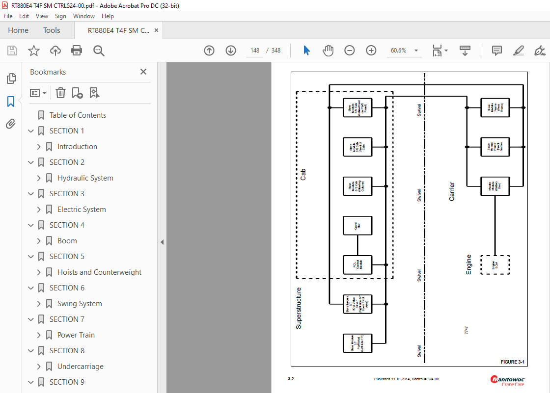
Electric System147
Description147
General147
Alternator149
Batteries149
Cab Electrical Panel149
Carrier Electrical Panel152
Maintenance153
General153
Visual Inspection and Replacement of Electrical Harnesses and Cables153
General Troubleshooting155
Troubleshooting Swivel-Caused Electrical Problems155
Connector Troubleshooting155
Alternator/Charging System Troubleshooting157
Required Tools157
Visual Check157
Engine Off Tests157
Batteries157
Load Test157
Voltage at Alternator157
Battery Drain157
Engine On Tests157
Output Voltage Test157
Maximum Amperage Test157
Voltage Drop Test158
Alternator Replacement158
Removal158
Installation158
Check158
Starter Replacement158
Removal158
Installation159
Check159
Battery Replacement159
Removal159
Installation159
Relay Panel Component Replacement159
Accessory Relay159
Buzzer Replacement160
Gauge Cluster Replacement160
Removal160
Installation160
Check160
Rocker Switch Replacement160
Removal160
Inspection161
Installation161
Check161
Ignition Switch Replacement161
Removal161
Inspection162
Installation162
Check162
Turn Signal Lever and Transmission Shift Lever Replacement162
Removal162
Installation162
Check163
Windshield Wiper Assembly Replacement165
Removal165
Inspection165
Installation165
Check166
Windshield Washer Assembly Replacement166
Removal166
Inspection166
Installation166
Check166
Skylight Wiper Assembly Replacement166
Removal166
Inspection166
Installation166
Check167
Troubleshooting167
Optional Equipment167
Description167
Beacon Light167
Boom Mounted Floodlights167
Rear View Mirror167
Air Conditioner167
Cold Weather Operation167
Component Coolant Heater167
Troubleshooting168
Maintenance Instructions168
SECTION 4169
Boom169
Description169
Lattice Extension169
Optional Lattice Extension Inserts169
Theory of Operation169
Boom Extension169
Boom Retraction170
Maintenance170
Removal170
Boom Disassembly170
Boom Nose Sheaves178
Removal178
Installation179
Boom Assembly179
Installation182
Functional Check182
Inspection183
Boom Alignment and Servicing183
Cam Operated Check Valve Adjustment183
Stop Block Adjustment183
Front Upper Pad Adjustment183
Read Side Wear Pad Adjustment183
Boom Extension and Retraction Cable184
Maintenance184
Inspection184
Adjustment184
Telescope Circuit186
Description186
Theory of Operation186
Maintenance186
Troubleshooting186
Removal and Installation188
Disassembly and Assembly188
Lift Circuit189
Description189
Theory of Operation189
Maintenance189
Troubleshooting189
Lift Cylinder Removal191
Lift Cylinder Installation191
Auxiliary Boom Nose193
Description193
Installing the Bi-Fold Manual Boom Extension193
Checking the Transport Condition196
Transport Condition with Lattice Extension Folded at the Side196
If 23 ft (7 m) Section and 33 ft (101 m) Section are Folded at the Side:196
If the 23 ft (7 m) Section Only is Folded at the Side:196
If the 23 ft (7 m) Section Only is Folded at the Side:196
Boom Extension Erecting and Stowing Procedure196
Monthly Maintenance Work196
Pins196
Hook Block197
Description197
Maintenance197
Periodic Maintenance197
SECTION 5199
Hoists and Counterweight199
Description199
Theory of Operation199
Maintenance200
Warm-up Procedure200
Routine Maintenance and Inspection200
Weekly or at 40 Hours of Operation (whichever comes first)200
Every Three Months or 300 Hours of Operation (whichever comes first)200
Annually200
Every Ten Years or 10,000 Hours (whichever comes first)200
Removal200
Installation201
Functional Check202
Fluid Level202
Hoist to Boom Alignment203
Preparation203
Tools Required203
Procedure203
Piston Motor and Control Valve204
Description204
Maintenance204
Removal204
Installation204
Idler Drum and Cable Follower204
Description204
Maintenance205
Idler Drum205
Removal and Disassembly205
Cleaning and Inspection205
Assembly and Installation205
Cable Follower205
Removal and Disassembly205
Cleaning and Inspection205
Assembly and Installation205
Complete Assembly206
Removal206
Installation206
Hoist Drum Rotation Indicator System207
Description207
Maintenance207
General207
Troubleshooting207
Removal207
Installation207
Counterweight Removal209
Removal of Standard Counterweight and Auxiliary Hoist209
Installation of Standard Counterweight and Auxiliary Hoist Mounting Structure209
Removal of Counterweight without Auxiliary Hoist209
Installation of Counterweight Without Auxiliary Hoist211
Third Wrap Indicator (Optional— Standard on CE)213
Description213
Maintenance213
SECTION 6215
Swing System215
Introduction215
Description215
Theory of Operation215
Swing Drive215
Swing Brake215
Maintenance217
Troubleshooting217
Swing Motor220
Description220
Maintenance220
Removal220
Installation220
Test220
Swing Gearbox and Brake220
Description220
Maintenance220
Swing Brake220
Removal220
Installation221
Testing221
Gearbox221
Removal221
Installation221
Servicing221
Checking the Oil Level222
Testing222
Swing Bearing222
Description222
Maintenance222
General222
Torquing Turntable Bolts222
General222
Tools Required223
Inner Race Torquing223
Outer Race Torquing223
Removal224
Inspection225
Installation225
Testing226
Swivels226
Description226
Hydraulic Swivel228
Description228
Theory of Operation228
Maintenance228
Removal228
Installation229
Two Port Water Swivel229
Description229
Maintenance229
Removal229
Disassembly230
Cleaning and Inspection230
Assembly230
Installation230
Electrical Swivel230
Description230
Theory of Operation230
Maintenance230
Removal230
Installation231
Preventive Maintenance232
Slew Potentiometer Adjustment232
SECTION 7233
Power Train233
Engine233
Description233
Maintenance234
Engine Removal234
Engine Installation234
Engine Drive Belt235
Electronic Control System236
Engine Control System Switches and Indicator Lights236
Engine Diagnostic/Speed Control Switch236
Increment/Decrement Switch236
Engine Stop Light236
Engine Warning Light236
Fault Code Flashing Sequence237
The Engine Warning Light (amber) flashes at the beginning of a fault code sequence There will be a short 1- or 2-second pause after which the number of the recorded fault code will flash in the Engine Stop Light (red) To interpret the flash code, c237
Exhaust System Cleaning Indicator237
Exhaust System Cleaning Switch237
Inhibit Exhaust System Cleaning Indicator238
High Exhaust System Temperature238
Fuel System239
Description239
Fuel Tank239
Injection Fuel Pump240
Fuel Filter-Water Separator240
Maintenance240
Fuel Tank240
Removal240
Installation240
Fuel Filter-Water Separator240
Draining240
Air Intake and Exhaust System240
Description240
Air Intake241
Air Cleaner Checks241
Check for Filter Restriction241
Filter Element Replacement243
Element Cleaning243
Air Cleaner Body243
Precleaner244
Duct Work244
Charge-Air Cooler System245
Maintenance245
Exhaust System246
Tier 3246
Removal246
Installation246
Tier 4247
Removal247
Installation247
Diesel Exhaust Fluid (DEF) System249
DEF Tank249
Removal249
Installation249
DEF Supply Module249
Removal249
Installation250
Filter Replacement250
Clean and Inspect for Reuse250
Filter Installation251
Water Cooling System251
Description251
Maintenance251
General251
Effects of Cooling System Neglect251
Overheating251
Overcooling251
Rust Prevention251
Test Equipment252
Engine Antifreeze/Coolant Fill Procedure252
Cooling/SCA Maintenance Summary252
6 Months or 500 Hours252
1 Year or 1000 Hours252
Cleaning252
Pressure Flushing253
Component Inspection253
Radiator/Surge Tank253
Engine Water Jacket253
Water Pump254
Fans and Belts254
Thermostat254
Hoses and Clamps254
Test Equipment254
Antifreeze/Coolant254
Radiator Removal and Installation254
Removal254
Installation256
Drive Train257
Description257
Maintenance257
Drive Lines257
Removal257
Installation257
Lubrication257
Transmission/torque Converter259
Description259
Theory of Operation259
Maintenance260
General Information260
Troubleshooting260
Troubleshooting Procedures260
Hydraulic Checks261
Removal261
Installation262
Towing or Pushing262
Servicing the Crane After Transmission/Torque Converter Overhaul264
Lubrication264
Type of Oil264
Capacity264
Check Period264
Normal Drain Period264
Engine Block Heater265
SECTION 8267
Undercarriage267
Axles267
Description267
Maintenance268
Removal268
Cleaning268
Installation268
Wheel Alignment Check Procedure269
Rear Wheels Not Centered Switch Adjustment Procedure269
Wheels and Tires270
Description270
Maintenance270
Mounting Wheel Assemblies270
Typical Wear Patterns271
Incorrect Tire Pressure271
Incorrect Camber271
Incorrect Toe and Axle Alignment271
Incorrect Caster and Wheel Imbalance271
Cuts in the Tire Tread272
Spot Wear272
Feathered Edges272
Cupping272
Steering Systems273
Description273
Front Steering System273
Rear Steering System273
Secondary Steering System (CE Units)273
Theory of Operation273
Front Steering System273
Rear Steering System273
Secondary Steering System (CE Units)273
Maintenance274
Front Steering System274
Troubleshooting274
Functional Check275
Rear Steering System275
Troubleshooting275
Hydraulic Pumps276
Description276
Front Steer276
Rear Steer276
Front Steering Control Valve276
Description276
Maintenance276
Removal276
Installation276
Rear Steer/ Axle Lockout/Fan Drive Valve276
Description276
Maintenance276
Removal276
Installation276
Functional Check277
Steer Cylinders277
Description277
Maintenance277
Removal277
Installation277
Rear Axle Oscillation Lockout System277
Description277
Theory of Operation277
Axle Oscillation Lockout Cylinders279
Description279
Maintenance279
Removal279
Installation279
Axle Oscillation Lockout Valve279
Description279
Maintenance279
Removal279
Installation279
Brake System280
Description280
Service Brakes280
Parking Brake280
Theory of Operation280
Service Brakes280
Parking Brake280
Maintenance281
Troubleshooting281
General281
Bleeding the Brake System281
Pressure Bleeding the Brake System282
Manually Bleeding the Brake System282
Service Brakes282
Description282
Maintenance282
Removal282
Linings282
Caliper282
Disassembly283
Caliper283
Inspection284
Periodic On-Vehicle284
Shoes, Linings, and End Plates284
Caliper for Leaks284
Dust Seals285
Disc285
Caliper Parts285
Cleaning286
Corrosion Protection286
Assembly286
Caliper286
Installation287
Linings287
Caliper287
Parking Brake Actuator288
Description288
Maintenance288
Removal288
Installation288
Adjustment288
Parking Brake289
Description289
Maintenance289
Removal289
Installation289
Park Brake Solenoid Valve292
Description292
Maintenance292
Removal292
Installation292
Outriggers293
Outrigger Circuit293
Theory of Operation293
Maintenance294
Troubleshooting294
Outrigger Beam297
Description297
Theory of Operation297
Maintenance297
Removal297
Inspection297
Installation298
Wear Pad Adjustment298
Extension Cylinder301
Description301
Maintenance301
Removal301
Installation301
Functional Check301
Outrigger Monitoring System (Optional— Standard in North America)302
Description302
Removal302
Installation302
Jack Cylinder302
Description302
Maintenance302
Removal302
Installation303
Functional Check303
Outrigger Jack Cylinder Internal Leak Test303
Checking Cylinder for Internal Piston Seal Leak303
Testing Pilot Operated Check Valve For Leakage304
Outrigger Control Valves304
Description304
Pilot Operated Check Valve304
Integrated Outrigger/Rear Steer Valve304
Outrigger Control Manifold304
Optional Equipment304
Pintle Hook304
Secondary Front Steer (CE Option)304
SECTION 9305
Lubrication305
General305
Environmental Protection305
Lubrication Intervals305
Standard Lubricants306
Arctic Lubricants and Conditions307
Temperatures Below -9°C (15°F)307
Cold Weather Package and Lubricants307
Surface Protection for Cylinder Rods310
Wire Rope Lubrication311
Lubrication Points311
CraneLUBE311
Safety311
Steering and Suspension312
Axles314
Drive Train316
Drive Train (continued)319
Turntable321
Cab Tilt323
Outriggers325
Boom327
Boom (continued)329
Boom (continued)331
Hoist333
Hydraulic335
Diesel Exhaust Fluid (DEF)337
Carwell® Rust Inhibitor339
Protecting Cranes From Rusting339
Cleaning Procedures339
Inspection and Repair340
Application340
Areas of Application340
IMAGES PREVIEW OF THE MANUAL:
More products