$28
Manitowoc Grove RT9130E-2 SERVICE Manual – PDF DOWNLOAD
Manitowoc Grove RT9130E-2 SERVICE Manual – PDF DOWNLOAD
FILE DETAILS:
Manitowoc Grove RT9130E-2 SERVICE Manual – PDF DOWNLOAD
Language : English
Pages :360
Downloadable : Yes
File Type : PDF
TABLE OF CONTENTS:
Manitowoc Grove RT9130E-2 SERVICE Manual – PDF DOWNLOAD
See end of this Manual for Alphabetical Index 5
SECTION 1 15
Introduction 15
Description 15
List Of Specifications 16
General 16
Dimensions 16
Capacities 16
Torque Converter 16
Transmission 16
Engine 16
Cummins QSL or (QSC) 16
Axles 16
Brakes 17
Wheels And Tires 17
Swing Gearbox 17
Boom 17
Swivel Assembly 17
Hydraulic Pumps 17
Pump #1 17
Pump #2 17
Pump #3 17
Pump #4 17
Hoists 17
Component Location 21
General Maintenance 24
Cleanliness 24
After Cleaning 24
Removal and Installation 24
Disassembly and Assembly 24
Pressing Parts 25
Locking Devices 25
Wires and Cables 25
Shims 25
Hoses and Tubes 25
Inspection 25
Installation 26
Bearings 26
Antifriction Bearings 26
Double Row, Tapered Roller 26
Heating Bearings 26
Installation 26
Preload 26
Sleeve Bearings 26
Gaskets 26
Batteries 26
Hydraulic Systems 27
Cleanliness 27
Keep the System Clean 27
Sealing Elements 27
Hydraulic Lines 27
Visual Inspection of Hoses and Fittings 27
Hydraulic Fittings 29
Flats from Finger Tight (FFFT) Method 29
37° Flared Steel Fitting: Tube or Hose to Fitting 29
Adjustable Straight Thread O-Ring Fittings 29
Nonadjustable Straight Thread O-Ring Fitting: Fitting to Port 30
Electrical System 31
Harnesses, Wires, and Connectors 31
Fatigue of Welded Structures 31
Loctite 31
Application of Medium Strength Loctite 31
Primer Application 31
Adhesive/Sealant Application 31
Fasteners and Torque Values 32
Torque Wrenches 32
Torque Values 32
Weld Studs 35
Wire Rope 36
General 36
Environmental Conditions 36
Dynamic Shock Loads 36
Lubrication 36
Precautions and Recommendations During Inspection or Replacement 36
Wire Rope Inspection—Running Ropes and Pendant Cables 37
Keeping Records 37
Frequent Inspection 37
Periodic Inspection 38
Wire Rope Inspection—Boom Extension and Retraction Cables 38
Periodic Inspection 38
Wire Rope Inspection/Replacement (All Wire Rope) 38
Seizing Wire Rope 39
Method 1 39
Method 2 39
Installing 35×7 Class Wire Rope Wire Rope 40
Procedures for Cutting and Preparing 35×7 Class Wire Rope 40
SECTION 2 43
Hydraulic System 43
Description 44
Hydraulic Oil Recommendations 44
Draining and Flushing 47
Removing Air from the Hydraulic System 48
Parts Replacement 48
Directional Control Valves 48
Inspection 48
Valve Leakage 48
Binding Spools 49
Visual Inspection of Hoses and Fittings 49
Supply Pressure And Return Circuit 50
Description 50
Hydraulic Reservoir and Filter 50
Pump Distribution 51
Pump No 1 51
Pump No 2 52
Pump No 3 52
Pump No 4 52
Maintenance 52
Troubleshooting 52
Filter Maintenance 54
Filter Element Removal 54
Filter Element Installation 54
Hydraulic Reservoir Removal 56
Hydraulic Reservoir Installation 56
Breather Removal and Replacement 56
Oil Cooler 57
Description 57
Hydraulic Pumps 58
Description 58
Pump No 1 58
Pump No 2 58
Pump No 3 58
Pump No 4 58
Maintenance 58
Pump No 1 Removal 58
Pump No 1 Installation 58
Pump No 2 Removal 58
Pump No 2 Installation 59
No 3 Pump Removal 59
No 3 Pump Installation 59
No 4 Pump Removal 60
No 4 Pump Installation 60
Testing After Repair or Replacement 60
Pressure Setting Procedures 63
Procedure A – For Setting Main Directional Control Valve Relief Pressures 64
Procedure B – For Checking Pressure Reducing/Sequence Valve Setting 66
Procedure for Checking Sequence Valve Setting (see Figure 2-8) 66
Procedure for Checking Controller Supply Pressure Reducing Valve Setting 66
Procedure C – For Checking Swing Brake Supply Pressure 66
Procedure D – For Checking Service Brake and Air Conditioning Circuit Relief Valve Pressure 66
Procedure E – For Checking Service Brake Dual Accumulator Charge Valve Pressure Limits 67
Procedure F – For Checking Accumulator Pre-Charge Pressure 68
Procedure G – For Pre-Charging Accumulator 68
Procedure H – For Checking Front Steer Relief Valve Pressure 68
Procedure I – For Checking Swing Valve Work Port Relief Pressure 69
Procedure J – For Checking Relief Setting for Counterweight Supply Control Valve 69
Procedure K – For Checking Outrigger/Rear Steer Relief Valve Pressure 71
Procedure L – For Checking/Setting the Make-up Oil Manifold (Thermal Contraction) 71
Procedure M – For Checking Charge Air Cooler Circuit Relief Valve Pressure (Tier 3 Only) 72
Checking Charge Air Cooler (CAC) Motor Control Valve – Tier 3 Only 72
Valves 73
General 73
Directional Control Valves 76
Description 76
General 76
Main Directional Valve (Hoist/Telescope/Lift) 76
Swing and Front Steer Directional Valve 76
Counterweight Removal/Cab Tilt Directional Control Valve 76
Maintenance 76
Hoist/Lift/Telescope Directional Valve Removal 76
Hoist/Lift/Telescope Directional Valve Installation 76
Swing/Steer Directional Valve Removal 76
Swing/Steer Directional Valve Installation 76
Counterweight Removal/Cab Tilt Directional Valve Removal 76
Counterweight Removal/Cab Tilt Directional Valve Installation 77
Functional Check (Both Valve Banks) 77
Function Check – LMI Lockout Valves 77
Swing Series Parallel Selector Valve 81
Description 81
Maintenance 81
Removal 81
Installation 81
Pressure Reducing Sequence Valve With Solenoid Controls Manifold 82
Description 82
Maintenance 82
Removal 82
Installation 82
Swing Brake Release Valve-Function Check 82
Crane Function Valve-Function Check 82
Steering Control Valve-Dual Displacement 84
Description 84
Maintenance 84
Removal 84
Installation 84
Dual Motor control Valve 85
Description 85
Maintenance 85
Removal 85
Installation 85
Hydraulic Remote Control Valve 86
Single Axis Control Valves 86
Dual Axis Control Valves (Optional) 86
Maintenance 86
Armrest Control Valve Removal 86
Armrest Control Valve Installation 86
Armrest Control Valve Functional Check 86
Telescope Pedal Control Valve Removal 86
Telescope Pedal Control Valve Installation 86
Telescope Pedal Control Valve Functional Check 86
Swing Power Brake Valve 88
Description 88
Maintenance 88
Removal 88
Installation 88
Function Check 88
Double Pilot Operated Check Valve 89
Description 89
Maintenance 89
Removal 89
Repair 89
Installation 89
Tandem Brake Valve w/ Treadle Pedal 90
Description 90
Maintenance 90
Removal 90
Installation 90
Dual Accumulator Charge Valve 91
Description 91
Maintenance 91
Removal 91
Installation 91
Service Brake Hydraulic Accumulator 92
Description 92
Maintenance 92
Removal 92
Installation 92
Servicing 92
Load Sense Hydraulic Accumulator 92
Description 92
Maintenance 92
Removal 92
Installation 92
Servicing 92
Holding Valves 93
Description 93
Maintenance 93
Removal 93
Repair 93
Installation 93
Lower Lift Cylinder Holding Valve 93
Removal 93
Installation 94
Shuttle Valve 94
Description 94
Maintenance 94
Removal 94
Installation 94
Solenoid Valves 95
Description 95
Oil Cooler Motor Control Solenoid Valve 95
Cold Air Charge Fan Control Solenoid Valve 95
Telescope Rod Drain Solenoid Valve 95
Outrigger Boost Solenoid Valve 95
Parking Brake Solenoid Valve 95
Axle Disconnect Solenoid Valve 95
Telescope Two-Stage Relief Solenoid Valve 95
Cross-Axle Differential Lock Solenoid Valve 95
Maintenance 95
Removal 95
Installation 96
Cross Axle Differential Lock Valve 96
Description 96
Maintenance 96
Removal 96
Installation 96
Check Valves 96
Description 96
Maintenance 96
Removal 96
Installation 96
Outrigger/Rear Steer/Outrigger Box Pin Removal Valve 97
Description 97
Maintenance 97
Removal 97
Installation 97
Functional Check 97
Outrigger Control Manifold 99
Description 99
Maintenance 99
Removal 99
Inspection 99
Installation 99
Functional Check 99
Pilot Operated Check Valve100
Description100
Maintenance100
Removal100
Installation100
Pressure Bleed-Off Valve101
Description101
Maintenance101
Removal101
Installation101
Axle Oscillation Lockout Valve103
Description103
Maintenance103
Removal103
Installation103
Relief Valve103
Description103
Maintenance103
Removal103
Installation103
Telescope Cylinder Charge Valve Manifold (If Equipped)104
Description104
Checking/Setting the Charge Valve Manifold104
Maintenance104
Removal104
Installation104
Checking Charge Air Cooler Motor Control Valve – For Tier 3 ONLY107
Cylinders108
General108
Maintenance108
Surface Protection For Cylinder Rods108
Leakage Check108
Temperature Effects on Hydraulic Cylinders109
Lift Cylinder111
Description111
Maintenance111
Disassembly111
Inspection111
Assembly113
Dual Rod Telescope Cylinder115
Description115
Maintenance115
Disassembly115
Inspection116
Assembly116
Upper Telescope Cylinder119
Description119
Maintenance119
Disassembly119
Inspection119
Assembly119
Axle Oscillation Lockout Cylinder122
Description122
Maintenance122
Disassembly122
Inspection122
Assembly122
Steer Cylinder124
Description124
Maintenance124
Disassembly124
Inspection125
Assembly125
Outrigger Extension Cylinder128
Description128
Maintenance128
Disassembly128
Inspection128
Assembly128
Outrigger Stabilizer Cylinder130
Description130
Maintenance130
Disassembly130
Inspection131
Assembly132
Tilt Cylinder133
Description133
Maintenance133
Disassembly133
Inspection134
Assembly134
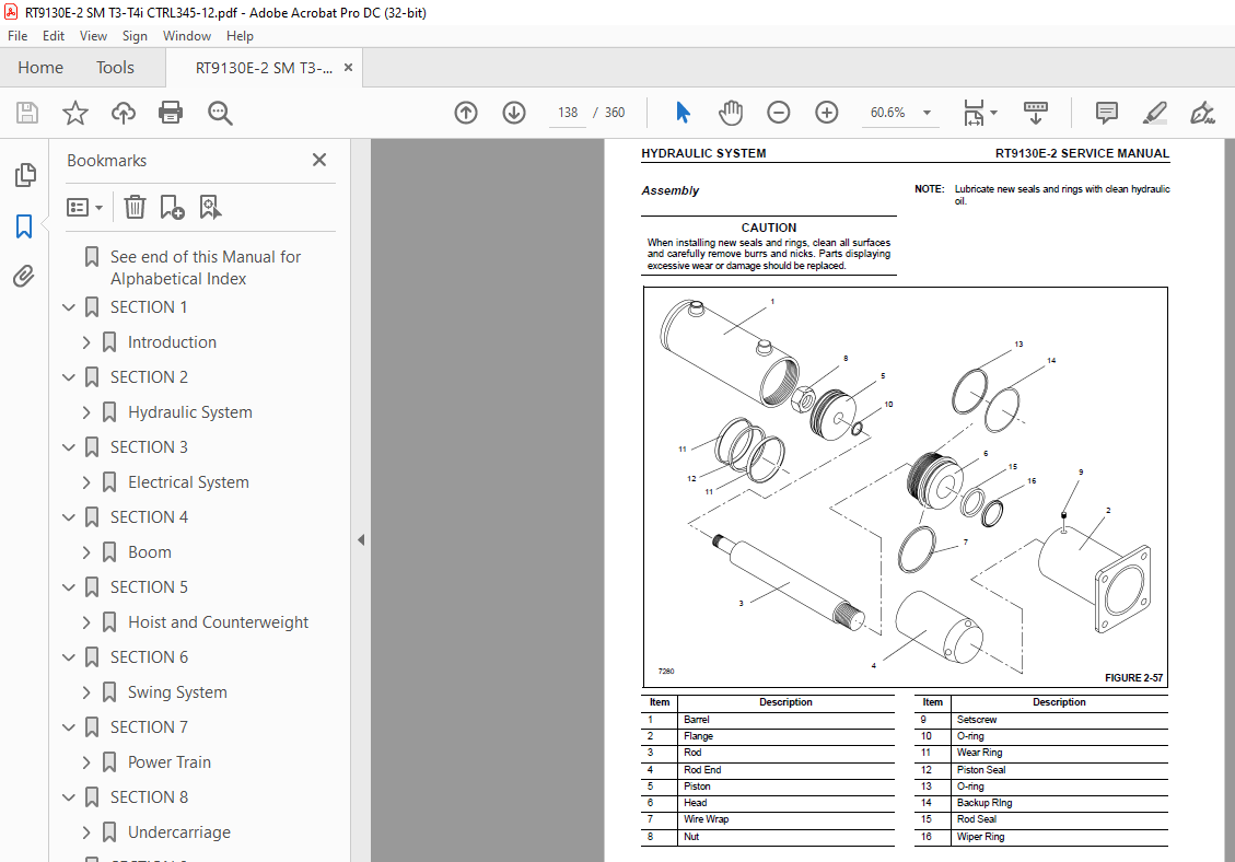
Power Pin Cylinder137
Description137
Maintenance137
Disassembly137
Inspection137
Assembly138
Park Brake Cylinder139
Description139
SECTION 3141
Electrical System141
Description141
General141
Alternator141
Batteries142
Fuse Panel142
Relays143
Maintenance146
General146
General Troubleshooting146
Troubleshooting Engine Starting Problems146
Troubleshooting Engine Charging Problems147
Troubleshooting Accessories147
Troubleshooting Swivel-Caused Electrical Problems147
Connector Troubleshooting147
Indicator Lights149
Troubleshooting Crane Components and Accessories150
Alternator Replacement150
Removal150
Installation150
Check150
Starter Replacement150
Removal150
Installation151
Check151
Battery Replacement151
Removal151
Installation151
Relay Panel Component Replacement151
Accessory Relay151
Buzzer Replacement152
Gauge Cluster Replacement152
Removal152
Installation152
Check153
Rocker Switch Replacement153
Removal153
Inspection153
Installation153
Check153
Ignition Switch Replacement153
Removal153
Inspection154
Installation154
Check154
Turn Signal Lever and Transmission Shift Lever Replacement154
Removal154
Installation155
Check155
Windshield Wiper Assembly Replacement157
Removal157
Inspection157
Installation157
Check158
Windshield Washer Assembly Replacement158
Removal158
Inspection158
Installation158
Check158
Skylight Wiper Assembly Replacement158
Removal158
Inspection159
Installation159
Check159
Telescope Cylinder Charge System – Electrical Schematic (If Equipped)159
Tools For Troubleshooting161
Optional Equipment161
Beacon Light161
Boom Mounted Floodlights161
Rear View Mirror161
Air Conditioner161
Cold Weather Operation161
Component Coolant Heater161
Troubleshooting162
Maintenance Instructions162
SECTION 4163
Boom163
Description163
Lattice Extension163
Optional Lattice Extension163
Optional Lattice Extension Inserts163
Boom Control Switches164
Boom Auto/Manual Telescope Mode Switches164
Center Mid/Inner Mid Boom Telescope Sections Select Switch164
Luffing Jib Switches164
Theory Of Operation164
Boom Extension164
Boom Retraction165
Rated Capacity Limiter (RCL) System (with Boom Control System)165
General165
Telescoping Control System Description165
Boom Configuration165
Extension/Retraction Modes165
Extension/Retraction Sequence (Automatic Mode)165
Extension Sequence For the Main Boom166
Extension Sequence for the Main Boom with Boom Extensions or Offset Jibs166
Rated Boom Lengths166
Capacities at Intermediate Boom Lengths166
Hydraulic Actuation and Control System167
Electronic Control System168
System Interfaces and Logic168
Boom Maintenance169
Removal169
Boom Disassembly170
Boom Nose Sheaves177
Removal177
Installation177
Additional Maintenance, Disassembled Boom178
Boom Assembly178
Installation182
Functional Check183
Inspection183
Boom Alignment and Servicing183
Cam Operated Check Valve Adjustment184
Guide Block Adjustment184
Boom Extension and Retraction Cables184
Maintenance184
Inspection184
Adjustment185
Telescope Circuit186
Description186
Theory Of Operation186
Maintenance187
Removal and Installation189
Disassembly and Assembly189
Hose Reel190
Description190
Maintenance190
Service190
Removal190
Installation190
Hose Reel Alignment192
Lift Circuit194
Description194
Theory Of Operation194
Maintenance194
Troubleshooting194
Removal196
Disassembly and Assembly196
Installation196
Boom Removal System201
Description201
Maintenance201
Upper Lift Cylinder Pin and Cylinder Disassembly201
Upper Lift Cylinder Pin and Cylinder Assembly201
Boom Pivot Shafts and Cylinder Disassembly201
Boom Pivot Shafts and Cylinder Assembly201
Bi-Fold Swingaway Boom Extension203
Description203
Identification203
Hookblock203
Description203
Maintenance203
SECTION 5205
Hoist and Counterweight205
Description205
Theory Of Operation205
Maintenance206
Warm-up Procedure206
Troubleshooting207
Removal209
Installation211
Functional Check211
Usage and Inspection211
Preventative Maintenance211
Oil Sampling213
Oil Change213
Gear Oil Sampling and Analysis213
Brake Test Procedure213
Hoist to Boom Alignment214
Preparation214
Tools Required214
Procedure214
Motor And Brake216
Description216
Maintenance216
Installation216
Idler Drum and Cable Follower217
Description217
Maintenance217
Idler Drum217
Removal and Disassembly217
Cleaning and Inspection217
Assembly and Installation217
Cable Follower217
Removal And Disassembly217
Cleaning and Inspection217
Assembly and Installation217
Complete Assembly218
Removal218
Installation218
Third Wrap Indicator220
Description220
Maintenance220
Removal220
Installation220
Hoist Drum Rotation Indicator System222
Description222
Maintenance222
General222
Rotation Sensor222
Thumb Thumper Solenoid222
Troubleshooting222
Hoist Rotation Indicator (HRI) Display System223
Pressure Switches223
HRI Display224
HRI Control Module224
Counterweight Removal and Installation225
Counterweight Stand Installation225
Standard and Heavy Counterweight and Auxiliary Hoist Structure226
Removal226
Installation229
Counterweight Stand Removal230
SECTION 6231
Swing System231
Description231
Theory Of Operation232
Swing Drive232
Swing Brake232
Maintenance234
Troubleshooting234
Swing Box Assemblies238
Description238
Swing Motor Maintenance238
Removal238
Installation238
Testing238
Swing Brake Assembly Maintenance239
Removal239
Installation239
Testing239
Swing Gearbox Maintenance239
Removal239
Installation239
Servicing240
Normal maintenance should only consist of proper lubrication and a periodic check of mounting bolt torque values Lubrication consists of maintaining the gearbox oil level Oil in a new gearbox should be drained and flushed after approximately 250 ho240
Oil Changing240
Checking Oil Level240
Testing240
Swing Bearing241
Description241
Maintenance241
General241
Torquing Turntable Bolts241
General241
Torque Values241
Tools Required241
Inner Race Torquing241
Outer Race Torquing241
Removal243
Inspection244
Installation244
Testing245
Swivels246
Description246
Hydraulic Swivel248
Description248
Theory Of Operation248
Maintenance248
Removal248
Installation249
Two-Port Water Swivel249
Description249
Maintenance249
Removal249
Disassembly249
Cleaning and Inspection250
Assembly250
Installation250
Electrical Swivel250
Description250
Theory Of Operation250
Maintenance250
Removal250
Installation251
Preventive Maintenance251
Slew Potentiometer Preliminary Zero Adjustment Procedure252
Slew Potentiometer Adjustment252
Swing Lock Pin253
Description253
Maintenance253
360° Swing Lock Control—Positive Lock Type (Optional)253
Description253
Maintenance253
SECTION 7255
Power Train255
Description255
Maintenance256
Engine Removal256
Engine Installation257
Engine Drive Belts258
Electronic Control System259
Engine Control System Switches and Indicator Lamps259
Engine Diagnostic Test Mode Switch259
The Diagnostic Test Mode Switch is used when servicing the engine’s electronic control system It is a two position on/off rocker switch used to activate the testing mode (fault codes) When the test mode switch is on, and used in conjunction with 259
Diagnostic/Idle Switch259
Manual DPF Regen Switch259
Emergency Stop Switch259
Engine Warning Indicator259
Disable Regeneration Indicator259
High Exhaust System Temperature Indicator259
Engine Wait To Start Indicator259
Emergency Engine Stop Indicator259
Fuel System259
Description259
Fuel Tank259
Injection Fuel Pump260
Fuel Filter-Water Separator260
Electric Lift Pump260
Maintenance260
Fuel Tank260
Removal260
Installation260
Fuel Filter-Water Separator260
Draining260
Air Intake and Exhaust System263
Description263
Maintenance263
Air Cleaner Checks263
Check for Filter Restriction263
Tier 3 Filter Element Replacement266
Air Cleaner Body266
Tier 4 Filter Element Replacement267
Element Cleaning267
Air Cleaner Body267
Precleaner267
Vacuator Valve267
Duct Work268
Charge-Air Cooler System269
Maintenance269
Muffler270
Removal270
Installation270
Water Cooling System272
Description272
Maintenance273
General273
Effects of Cooling System Neglect273
Overheating273
Overcooling273
Antifreeze/Coolant273
Rust Prevention273
Engine Antifreeze/Coolant Fill Procedure (when level is low)273
Antifreeze/Supplemental Coolant Additives Maintenance Summary274
Cooling System Level Check Interval274
SCA Level Check/Coolant Filter Change Interval274
Cleaning274
Pressure Flushing274
Component Inspection275
Radiator/Surge Tank275
Engine Water Jacket275
Water Pump275
Fans and Belts276
Thermostat276
Hoses and Clamps276
Test Equipment276
Antifreeze/Coolant276
Radiator Removal and Installation276
Removal276
Installation276
Drive Train279
Description279
Maintenance279
Drive Lines279
Removal279
Installation279
Lubrication279
Torque Converter280
Description280
Theory of Operation280
Maintenance281
General Information281
Troubleshooting281
Hydraulic Checks281
Troubleshooting Procedures281
Removal282
Installation282
Servicing the Crane After Transmission/Torque Converter Overhaul284
Lubrication284
Type Of Oil284
Capacity284
Check Period284
Normal Drain Period285
Transmission285
Description285
Maintenance285
Removal285
Installation285
Towing or Pushing285
SECTION 8287
Undercarriage287
Axles287
Description287
Maintenance288
Removal288
Cleaning288
Installation288
Wheel Alignment Check Procedure288
Rear Wheels Not Centered Switch Adjustment Procedure289
Wheels and Tires290
Description290
Maintenance290
Mounting Wheel Assemblies290
Steering Systems291
Description291
Front Steering System291
Rear Steering System291
Theory of Operation291
Front Steering System291
Rear Steering System291
Maintenance291
Front Steering System291
Functional Check292
Rear Steering System293
Hydraulic Pumps294
Description294
Front Steer294
Rear Steer294
Front Steering Control Valve294
Description294
Maintenance294
Removal294
Installation294
Integrated Outrigger/Rear Steer Control Valve294
Description294
Maintenance294
Removal294
Installation294
Functional Check295
Steer Cylinders295
Description295
Maintenance295
Removal295
Installation295
Rear Axle Oscillation Lockout System295
Description295
Theory of Operation295
Axle Oscillation Lockout Cylinders297
Description297
Maintenance297
Removal297
Installation297
Axle Oscillation Lockout Valve297
Description297
Maintenance297
Removal297
Installation297
Brake System298
Description298
Service Brakes298
Parking Brake298
Theory of Operation298
Service Brakes298
Parking Brake298
Maintenance299
Troubleshooting299
General299
Bleeding the Brake System300
Service Brakes300
Description300
Maintenance300
Removal300
Disassembly300
Inspection302
Cleaning304
Corrosion Protection304
Assembly304
Installation305
Parking Brake Actuator306
Description306
Maintenance306
Removal306
Installation306
Adjustment306
Parking Brake306
Description306
Maintenance307
Removal307
Installation307
Park Brake Solenoid Valve308
Description308
Maintenance308
Removal308
Installation308
Outrigger Circuit309
Description309
Theory Of Operation309
Maintenance310
Outrigger Beam313
Description313
Theory Of Operation313
Maintenance314
Extension Cylinder318
Description318
Maintenance318
Outrigger Monitoring System (Optional—Standard in North America)319
Description319
Removal319
Installation319
Jack Cylinder319
Description319
Maintenance319
Outrigger Control Valves320
Description320
SECTION 9321
Lubrication321
General321
Environmental Protection321
Lubricants and Lubrication Intervals321
Standard Lubricants322
Arctic Lubricants and Conditions323
Temperatures Below -9°C (15°F)323
Cold Weather Package and Lubricants323
Surface Protection for Cylinder Rods325
Wire Rope Lubrication325
Lubrication Points325
CraneLUBE326
Cummins Oil Registration List326
Safety326
Steering and Suspension327
Axles329
Drive Train331
Drive Train (continued)333
Turntable335
Cab Tilt337
Outriggers339
Boom341
Boom (continued)343
Boom (continued)345
Hoist347
Hydraulic349
Instructions for Accessing Lubrication Points on Boom351
Carwell® Rust Inhibitor352
Protecting Cranes From Rusting352
Cleaning Procedures352
Inspection and Repair353
Application353
Areas of Application353
IMAGES PREVIEW OF THE MANUAL:
More products