$39
Mitsubishi Galant 2007 Workshop Manual – PDF DOWNLOAD
Mitsubishi Galant 2007 Workshop Manual – PDF DOWNLOAD
FILE DETAILS:
Mitsubishi Galant 2007 Workshop Manual – PDF DOWNLOAD
Language : English
Pages : 215
Downloadable : Yes
File Type : PDF
IMAGES PREVIEW OF THE MANUAL:
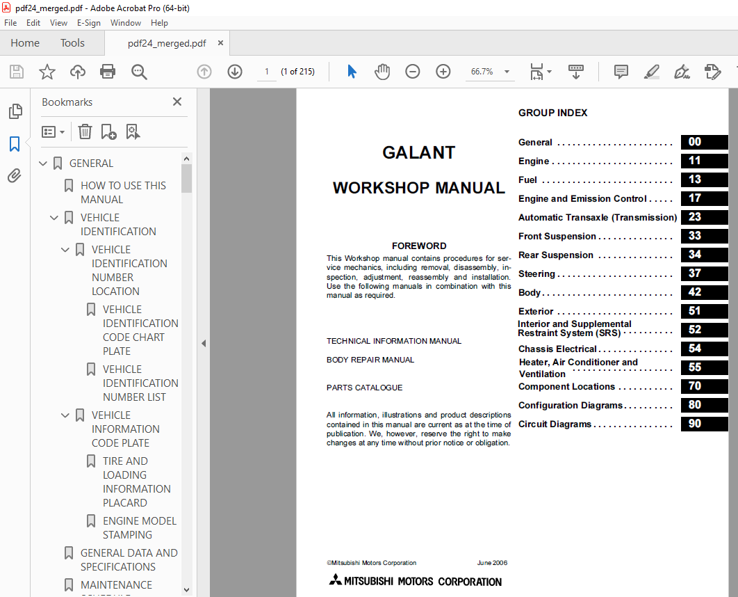
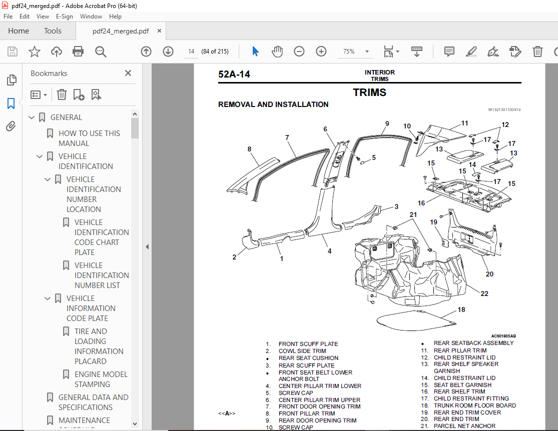
TABLE OF CONTENTS:
Mitsubishi Galant 2007 Workshop Manual – PDF DOWNLOAD
GENERAL 101
HOW TO USE THIS MANUAL 4
VEHICLE IDENTIFICATION 71
VEHICLE IDENTIFICATION NUMBER LOCATION 180
VEHICLE IDENTIFICATION CODE CHART PLATE 101
VEHICLE IDENTIFICATION NUMBER LIST 4
VEHICLE INFORMATION CODE PLATE 188
TIRE AND LOADING INFORMATION PLACARD 79
ENGINE MODEL STAMPING 189
GENERAL DATA AND SPECIFICATIONS 7
MAINTENANCE SCHEDULE 21
ENGINE 187
ENGINE MECHANICAL 187
GENERAL DESCRIPTION 172
CAMSHAFT AND VALVE STEM SEAL 10
ENGINE OVERHAUL 187
GENERAL DESCRIPTION 71
ROCKER ARMS AND CAMSHAFT 172
FASTENER TIGHTENING SPECIFICATIONS 13
MULTIPORT FUEL INJECTION (MFI) 187
GENERAL DESCRIPTION 59
OUTLINE OF CHANGE 15
MULTIPORT FUEL INJECTION (MFI) DIAGNOSIS 57
PROVISIONAL DTCs [OBD-II Test Mode – Results (Mode 7)] 110
MODE 6 REFERENCE TABLE 20
SYSTEM READINESS TEST STATUS 22
ON-VEHICLE SERVICE 51
EVAPORATVE EMISSION VENTILATION SOLENOID CHECK 51
SPECIFICATION(S) 51
ENGINE AND EMISSION CONTROL 187
EMISSION CONTROL 53
OUTLINE OF CHANGE 183
POSITIVE CRANKCASE VENTILATION SYSTEM 53
POSITIVE CRANKCASE VENTILATION SYSTEM CHECK 180
POSITIVE CRANKCASE VENTILATION VALVE CHECK 61
AUTOMATIC TRANSAXLE 187
GENERAL DESCRIPTION 178
FRONT SUSPENSION 187
GENERAL INFORMATION 61
SPECIFICATIONS 61
ON-VEHICLE SERVICE 57
FRONT WHEEL ALIGNMENT CHECK AND ADJUSTMENT 188
REAR SUSPENSION 187
GENERAL DESCRIPTION 61
ON-VEHICLE SERVICE 63
REAR WHEEL ALIGNMENT CHECK AND ADJUSTMENT 59
SPECIFICATIONS 59
POWER STEERING 187
GENERAL INFORMATION 61
ON-VEHICLE SERVICE 61
STEERING ANGLE CHECK 67
SPECIFICATIONS 73
BODY 187
GENERAL DESCRIPTION 71
FENDER 63
REMOVAL SERVICE POINT 65
INSTALLATION SERVICE POINT 188
EXTERIOR 187
GENERAL 67
FRONT BUMPER ASSEMBLY 85
REAR BUMPER ASSEMBLY 180
INTERIOR 187
GENERAL DESCRIPTION 72
INSIDE REAR VIEW MIRROR DIAGNOSIS 72
SYMPTOM PROCEDURES 73
The Inside Rear View Mirror can’t be Set to Night Mode 73
DIAGNOSIS 188
STEP 1 Check inside rear view mirror assembly connector D-49 for loose, corroded or damaged terminals, or terminals pushed back in the connector 75
STEP 2 Measure the voltage at inside rear view mirror assembly connector D-49 174
STEP 3 Check the wiring harness between inside rear view mirror assembly connector D-49 (terminal 1) and the ignition switch (IG2) 76
STEP 4 Measure the resistance at inside rear view mirror assembly connector D-49 77
STEP 5 Check the wiring harness between inside rear view mirror assembly connector D-49 (terminal 2) and ground 77
STEP 6 Measure the voltage at inside rear view mirror assembly connector D-49 78
STEP 7 Check transmission range switch connector B-110 for loose, corroded or damaged terminals, or terminals pushed back in the connector 189
STEP 8 Check the transmission range switch 79
STEP 9 Check the ignition switch (IG1) circuit to the backup light switch Measure the voltage at transmission range switch connector B-110 79
STEP 10 Check the wiring harness between transmission range switch connector B-110 (terminal 8) and the ignition switch (IG1) 191
STEP 11 Check the wiring harness between inside rear view mirror assembly connector D-49 (terminal 3) and transmission range switch connector B-110 (terminal 7) 82
STEP 12 Check the inside rear view mirror assembly 83
TRIMS 94
CHASSIS ELECTRICAL 101
GENERAL INFORMATION 86
IGNITION SWITCH 188
ON-VEHICLE SERVICE 87
ENCRYPTED CODE REGISTRATION PROCEDURE 87
PRECAUTIONS DURING SERVICE 87
ENCRYPTED CODE REGISTRATION USING IGNITION KEY <REGISTRATION USING SCAN TOOL MB991958 (M U T -III SUB ASSEMBLY)> 180
ENCRYPTED CODE REGISTRATION USING BARCODE NO 90
COMBINATION METER 181
ON-VEHICLE SERVICE 94
SPEEDOMETER CHECK 191
HEADLIGHT, FRONT SIDE MARKER LIGHT AND POSITION LIGHT ASSEMBLY 182
ON-VEHICLE SERVICE 95
HEADLIGHT LEVELING SWITCH CONTINUITY CHECK 96
REAR FOG LIGHT 96
REAR FOG LIGHT 97
INSPECTION 97
REAR FOG LIGHT RELAY CHECK 200
SIDE TURN-SIGNAL LIGHT 98
REMOVAL SERVICE POINT 99
INSTALLATION SERVICE POINT 100
LICENSE PLATE LIGHT 100
SIMPLIFIED WIRING SYSTEM (SWS) 101
GENERAL INFORMATION 188
OUITLINE OF CHANGE 102
SPECIAL TOOL 103
SYMPTOM CHART 180
INPUT SIGNAL CHART 106
SCAN TOOL OR VOLTMETER 106
SYMPTOM PROCEDURES 107
HEADLIGHT AND TAILLIGHT 107
INSPECTION PROCEDURE H-6: Headlight and Taillight: The taillights, the position lights or the license plate light do not illuminate 107
STEP 1 Check the operation of each light 191
STEP 2 Check joint connector C-01 and front-ECU connector A-11X for loose, corroded or damaged terminals, or terminals pushed back in the connector 109
STEP 3 Check the wiring harness between joint connector C-01 (terminal 1) and front-ECU connector A-11X (terminal 4) 110
STEP 4 Check joint connector C-01 and front-ECU connector A-11X for loose, corroded or damaged terminals, or terminals pushed back in the connector 110
STEP 5 Check the wiring harness between joint connector C-01 (terminal 18) and front-ECU connector A-11X (terminal 4) 111
STEP 6 Check joint connector C-01 for loose, corroded or damaged terminals, or terminals pushed back in the connector 191
STEP 7 Check the wiring harness between joint connector C-01 (terminal 4) and rear combination light (LH) connector F-09 (terminal 4) 182
STEP 8 Check rear combination light (LH) connector F-09 for loose, corroded or damaged terminals, or terminals pushed back in the connector 191
STEP 9 Check the tail light bulb (LH) 182
STEP 10 Check the ground circuit to the rear combination light (LH) Measure the resistance at rear combination light (LH) connector F-09 113
STEP 11 Check the wiring harness between rear combination light (LH) connector F-09 (terminal 2) and ground 114
STEP 12 Check the wiring harness between rear combination light (LH) connector F-09 (terminal 4) and intermediate connector C-25 (terminal 10) 114
STEP 13 Check rear combination light (RH) connector F- 03 for loose, corroded or damaged terminals, or terminals pushed back in the connector 115
STEP 14 Check the taillight bulb (RH) 115
STEP 15 Check the ground circuit to the rear combination light (RH) Measure the resistance at rear combination light (RH) connector F-03 115
STEP 16 Check the wiring harness between rear combination light (RH) connector F-03 (terminal 2) and ground 116
STEP 17 Check joint connector C-01 for loose, corroded or damaged terminals, or terminals pushed back in the connector 116
STEP 18 Check the wiring harness between rear combination light (RH) connector F-03 (terminal 4) and joint connector C-01 (terminal 22) 183
STEP 19 Check position light (LH) connector A-45 for loose, corroded or damaged terminals, or terminals pushed back in the connector 118
STEP 20 Check the position light bulb (LH) 118
STEP 21 Check the ground circuit to the position light (LH) Measure the resistance at position light (LH) connector A-45 118
STEP 22 Check the wiring harness between position light light (LH) connector A-45 (terminal 2) and ground 119
STEP 23 Check joint connector C-01 for loose, corroded or damaged terminals, or terminals pushed back in the connector 119
STEP 24 Check the wiring harness between position light light (LH) connector A-45 (terminal 1) and joint connector C-01 (terminal 3) 119
STEP 25 Check position light (RH) connector A-48 for loose, corroded or damaged terminals, or terminals pushed back in the connector 120
STEP 26 Check the position light bulb (RH) 120
STEP 27 Check the ground circuit to the position light (RH) Measure the resistance at position light (RH) connector A-48 120
STEP 28 Check the wiring harness between position light light (RH) connector A-48 (terminal 2) and ground 121
STEP 29 Check joint connector C-01 for loose, corroded or damaged terminals, or terminals pushed back in the connector 121
STEP 30 Check the wiring harness between position light light (RH) connector A-48 (terminal 1) and joint connector C-01 (terminal 19) 185
STEP 31 Check license plate light (LH) connector F-12 for loose, corroded or damaged terminals, or terminals pushed back in the connector 122
STEP 32 Check the wiring harness between license plate light (LH) connector F-06 (terminal 2) and ground 122
STEP 33 Check license plate light (LH) connector F-12 for loose, corroded or damaged terminals, or terminals pushed back in the connector 122
STEP 34 Check the license plate light (LH) bulb 122
STEP 35 Check the ground circuit to the license plate light (LH) Measure the resistance at license plate light (LH) connector F-12 123
STEP 36 Check the wiring harness between license plate light connector (LH) F-12 (terminal 2) and ground 123
STEP 37 Check intermediate connector C-25 for loose, corroded or damaged terminals, or terminals pushed back in the connector 185
STEP 38 Check the wiring harness between license plate light (LH) connector F-12 (terminal 1) and intermediate connector C-25 (terminal 10) 124
STEP 39 Check license plate light (RH) connector F-11 for loose, corroded or damaged terminals, or terminals pushed back in the connector 124
STEP 40 Check the license plate light (RH) bulb 124
STEP 41 Check the ground circuit to the license plate light (RH) Measure the resistance at license plate light (RH) connector F-11 125
STEP 42 Check the wiring harness between license plate light connector (RH) F-11 (terminal 2) and ground 125
STEP 43 Check intermediate connector C-25 for loose, corroded or damaged terminals, or terminals pushed back in the connector 125
STEP 44 Check the wiring harness between license plate light (RH) connector F-11 (terminal 1) and intermediate connector C-25 (terminal 10) 126
INSPECTION PROCEDURE H-7: Headlight and Taillight: One of the headlights does not illuminate 127
STEP 1 Check the headlight operation 128
STEP 2 Check headlight (LH) connector A-46 for loose, corroded or damaged terminals, or terminals pushed back in the connector 129
STEP 3 Check headlight (LH) bulb 129
STEP 4 Check the wiring harness between headlight (LH) connector A-46 (terminal 1) and ground 129
STEP 5 Check headlight (RH) connector A-47 for loose, corroded or damaged terminals, or terminals pushed back in the connector 129
STEP 6 Check the headlight (RH) bulb 130
STEP 7 Check the wiring harness between headlight (RH) connector A-47 (terminal 1) and ground 130
STEP 8 Check headlight (LH) connector A-46 and front- ECU connector A-11X for loose, corroded or damaged terminals, or terminals pushed back in the connector 130
STEP 9 Check headlight (LH) bulb 131
STEP 10 Check the wiring harness between headlight (LH) connector A-46 (terminal 2) and front-ECU connector A- 11X (terminal 6) 131
STEP 11 Check headlight (RH) connector A-47 and front- ECU connector A-11X for loose, corroded or damaged terminals, or terminals pushed back in the connector 132
STEP 12 Check the headlight (RH) bulb 132
STEP 13 Check the wiring harness between headlight (RH) connector A-47 (terminal 2) and front-ECU connector A- 11X (terminal 6) 133
STEP 14 Check headlight (LH) connector A-46 and front- ECU connector A-11X for loose, corroded or damaged terminals, or terminals pushed back in the connector 133
STEP 15 Check headlight (LH) bulb 134
STEP 16 Check the wiring harness between headlight (LH) connector A-46 (terminal 3) and front-ECU connector A- 11X (terminal 10) 134
STEP 17 Check headlight (RH) connector A-47 and front- ECU connector A-11X for loose, corroded or damaged terminals, or terminals pushed back in the connector 135
STEP 18 Check the headlight (RH) bulb 135
STEP 19 Check the wiring harness between headlight (RH) connector A-47 (terminal 3) and front-ECU connector A- 11X (terminal 10) 136
FLASHER TIMER 137
INSPECTION PROCEDURE I-3: Flasher Timer: One of the turn-signal lights does not illuminate 137
DIAGNOSIS 138
STEP 1 Check the hazard warning light 139
STEP 2 Check front turn signal light (LH) connector A-43 for loose, corroded or damaged terminals, or terminals pushed back in the connector 139
STEP 3 Check the front turn-signal light bulb (LH) 139
STEP 4 Check the ground circuit to the ETACS-ECU Measure the resistance at front turn signal light (LH) connector A-43 140
STEP 5 Check the wiring harness between front turn signal light (LH) connector A-43 (terminal 1) and ground 140
STEP 6 Check ETACS-ECU connector C-219 for loose, corroded or damaged terminals, or terminals pushed back in the connector 140
STEP 7 Check the wiring harness between front turn signal light (LH) connector A-43 (terminal 2) and ETACS- ECU connector C-219 (terminal 14) 141
STEP 8 Check front turn signal light (RH) connector A-49 for loose, corroded or damaged terminals, or terminals pushed back in the connector 142
STEP 9 Check the front turn-signal light bulb (RH) 142
STEP 10 Check the ground circuit to the front turn signal light (RH) Measure the resistance at front turn signal light (RH) connector A-49 142
STEP 11 Check the wiring harness between front turn signal light (RH) connector A-49 (terminal 1) and ground 143
STEP 12 Check ETACS-ECU connector C-219 for loose, corroded or damaged terminals, or terminals pushed back in the connector 143
STEP 13 Check the wiring harness between front turn signal light (RH) connector A-49 (terminal 2) and ETACS- ECU connector C-219 (terminal 9) 143
STEP 14 Check rear combination light (LH) connector F-09 for loose, corroded or damaged terminals, or terminals pushed back in the connector 144
STEP 15 Check the rear turn-signal light bulb (LH) 144
STEP 16 Check the ground circuit to the rear combination light (LH) Measure the resistance at rear combination light (LH) connector F-09 145
STEP 17 Check the wiring harness between rear combination light (LH) connector F-09 (terminal 2) and ground 145
STEP 18 Check ETACS-ECU connector C-219 for loose, corroded or damaged terminals, or terminals pushed back in the connector 146
STEP 19 Check the wiring harness between rear combination light (LH) connector F-09 (terminal 5) and ETACS-ECU connector C-219 (terminal 14) 146
STEP 20 Check rear combination light (RH) connector F- 03 for loose, corroded or damaged terminals, or terminals pushed back in the connector 147
STEP 21 Check the rear turn-signal light bulb (RH) 147
STEP 22 Check the ground circuit to the rear turn-signal light (RH) Measure the resistance at rear combination light (RH) connector F-03 148
STEP 23 Check the wiring harness between rear combination light (RH) connector F-03 (terminal 2) and ground 148
STEP 24 Check ETACS-ECU connector C-219 for loose, corroded or damaged terminals, or terminals pushed back in the connector 149
STEP 25 Check the wiring harness between rear combination light (RH) connector F-03 (terminal 5) and ETACS-ECU connector C-219 (terminal 9) 149
STEP 26 Check side turn signal light (LH) connector A-42 for loose, corroded or damaged terminals, or terminals pushed back in the connector 150
STEP 27 Check the side turn-signal light bulb (LH) 150
STEP 28 Check the ground circuit to the ETACS-ECU Measure the resistance at side turn signal light (LH) connector A-42 151
STEP 29 Check the wiring harness between side turn signal light (LH) connector A-42 (terminal 1) and ground 151
STEP 30 Check ETACS-ECU connector C-219 for loose, corroded or damaged terminals, or terminals pushed back in the connector 151
STEP 31 Check the wiring harness between side turn signal light (LH) connector A-42 (terminal 2) and ETACS- ECU connector C-219 (terminal 14) 152
STEP 32 Check side turn signal light (RH) connector A-51 for loose, corroded or damaged terminals, or terminals pushed back in the connector 153
STEP 33 Check the side turn-signal light bulb (RH) 153
STEP 34 Check the ground circuit to the side turn signal light (RH) Measure the resistance at side turn signal light (RH) connector A-51 153
STEP 35 Check the wiring harness between side turn signal light (RH) connector A-51 (terminal 1) and ground 154
STEP 36 Check ETACS-ECU connector C-219 for loose, corroded or damaged terminals, or terminals pushed back in the connector 154
STEP 37 Check the wiring harness between side turn signal light (RH) connector A-51 (terminal 2) and ETACS- ECU connector C-219 (terminal 9) 154
FOG LIGHT 155
ECU FUNCTIONS AND CONTROLS IN THE SWS 155
INSPECTION PROCEDURE J-5: The Rear Fog Light do not Illuminate Normally 156
DIAGNOSIS 157
STEP 1 Check the taillight operation 157
STEP 2 Use scan tool MB991958 to select “ECU COMM Check” on the SWS monitor display 158
STEP 3 ETACS switch data by using the SWS monitor 159
STEP 4 Check rear fog light relay connector A-09X for loose, corroded or damaged terminals, or terminals pushed back in the connector 159
STEP 5 Check the rear fog light relay 160
STEP 6 Check the battery power supply circuit to the rear fog light relay Measure the voltage at rear fog light relay connector A-09X 160
STEP 7 Check the wiring harness between rear fog light relay connector A-09X (terminals 1 and 2) and the battery 161
STEP 8 Check ETACS-ECU connector C-217 for loose, corroded or damaged terminals, or terminals pushed back in the connector 161
STEP 9 Check the wiring harness between rear fog light relay connector A-09X (terminal 3) and ETACS-ECU connector C-217 (terminal 40) 161
STEP 10 Check rear fog light connector F-13 for loose, corroded or damaged terminals, or terminals pushed back in the connector 162
STEP 11 Check the ground circuit to the rear fog light Measure the resistance at rear fog light connector F-13 162
STEP 12 Check the wiring harness between rear fog light connector F-13 (terminal 1) and ground 162
STEP 13 Check the wiring harness between rear fog light relay connector A-09X (terminal 4) and rear fog light connector F-13 (terminal 2) 163
INSPECTION PROCEDURE J-6: The Rear Fog Light Indicator does not Illuminate Normally 163
STEP 1 Check the rear fog light 164
STEP 2 Using scan tool MB991958, diagnose the CAN bus line 165
STEP 3 Using scan tool MB991958, read the combination meter diagnostic trouble code 165
STEP 4 Use scan tool MB991958 to select “ECU COMM Check” on the SWS monitor display 166
STEP 5 Replace the combination meter 166
INPUT SIGNAL PROCEDURES 167
INSPECTION PROCEDURE N-11: ETACS-ECU does not Receive Any Signal from the Rear Fog Light Switch 167
DIAGNOSIS 168
STEP 1 Check fog light switch connector C-128 for loose, corroded or damaged terminals, or terminals pushed back in the connector 168
STEP 2 Check the rear fog light switch 168
STEP 3 Check the ground circuit to the fog light switch Measure the resistance at fog light switch connector C- 128 169
STEP 4 Check the wiring harness between fog light switch connector C-128 (terminal 6) and ground 169
STEP 5 Check ETACS-ECU connector C-217 for loose, corroded or damaged terminals, or terminals pushed back in the connector 169
STEP 6 Check the wiring harness between fog light switch connector C-128 (terminal 1) and ETACS-ECU connector C- 217 (terminal 54) 170
AUTOMATIC AIR CONDITIONING 187
GENERAL DESCRIPTION 172
SYMPTOM PROCEDURES 172
When Sunlight Intensity Changes, Air Outlet Temperature Does Not Change 172
DIAGNOSIS 180
STEP 1 Check the defogger and outside/inside air selection damper control motor operation 173
STEP 2 Using scan tool MB991958, read diagnostic trouble code 180
STEP 3 Using scan tool MB991958, check data list item 06: Photo sensor 174
STEP 4 Check A/C-ECU connectors C-15, C-16 and photo sensor connector C-04 for loose, corroded or damaged terminals, or terminals pushed back in the connector 175
STEP 5 Check the wiring harness between photo sensor connector C-04 (terminal 1, 2) and A/C-ECU connector C-15 (terminal 19), C-16 (terminal 25) 176
STEP 6 Replace the photo sensor 180
STEP 7 Check the refrigerant level 176
COMPONENT LOCATIONS 187
RELAY 178
CONFIGURATION DIAGRAMS 187
ENGINE COMPARTMENT <VEHICLES FOR RUSSIA> 187
DASH PANEL <VEHICLES FOR RUSSIA> 181
FLOOR AND ROOF <VEHICLES FOR RUSSIA> 185
LUGGAGE COMPARTMENT <VEHICLES FOR RUSSIA> 186
CIRCUIT DIAGRAMS 187
CENTRALIZED JUNCTION <VEHICLES FOR RUSSIA> 188
FUSIBLE LINK AND FUSE 188
POWER DISTRIBUTION SYSTEM <VEHICLES FOR RUSSIA> 195
HEADLIGHT <VEHICLES FOR RUSSIA> 197
TAILLIGHT, POSITION LIGHT AND LICENSE PLATE LIGHT <VEHICLES FOR RUSSIA> 199
REAR FOG LIGHT <VEHICLES FOR RUSSIA> 201
HEADLIGHT LEVELING SYSTEM <VEHICLES FOR RUSSIA> 203
TURN-SIGNAL LIGHT AND HAZARD WARNING LIGHT <VEHICLES FOR RUSSIA> 205
CENTRAL DOOR LOCKING SYSTEM <VEHICLES FOR RUSSIA> 208
AUTOMATIC AIR CONDITIONING SYSTEM <VEHICLES FOR RUSSIA> 212
AUTOMATIC ANTI-DAZZLING MIRROR <VEHICLES FOR RUSSIA> 215

