$33.95
Mitsubishi S4S Diesel Engine Service Manual 99616-87100 – PDF DOWNLOAD
Mitsubishi S4S Diesel Engine Service Manual 99616-87100 – PDF DOWNLOAD
FILE DETAILS:
Mitsubishi S4S Diesel Engine Service Manual 99616-87100 – PDF DOWNLOAD
Language : English
Pages : 190
Downloadable : Yes
File Type : PDF
IMAGES PREVIEW OF THE MANUAL:
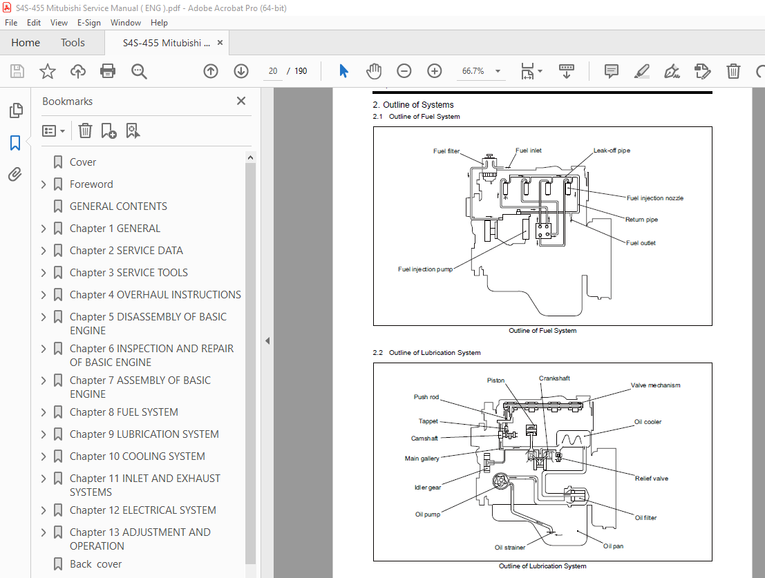
TABLE OF CONTENTS:
Mitsubishi S4S Diesel Engine Service Manual 99616-87100 – PDF DOWNLOAD
Cover 1
Foreword 3
HOW TO USE THIS MANUAL 4
Description format 4
Terms used in this manual 5
Nominal value 5
Standard value 5
Limit value 5
Abbreviations and Standards 5
Unit of Measurement 5
Safety Cautions 6
Fire and Explosion Precautions 6
Keep Flames Away 6
Keep Engine Surrounding Area Tidy and Clean 6
Pay Attention to Fuel, Oil and Exhaust Gas Leak 6
Use Explosion-Proof Light 6
Prevent Electrical Wires from Short Circuit 6
Keep Fire Extinguishers and First-Aid Kit Handy 6
Stay Away From Rotating and Moving Parts 7
Install Protective Covers Over Rotating Parts After Inspection and Maintenance Work 7
Check Work Area for Safety Before Starting 7
Stay Away From Moving Parts While Engine Operates 7
Lockout and Tagout 7
Be Sure to Stop the Engine Before Inspection and Maintenance 7
Always Put Back Engine Turning Tool After Use 7
Be Careful of Exhaust Gas Poisoning 8
Be Careful of Ventilation to Operate Engine 8
Be Careful of Hearing Loss 8
Wear Ear Plugs 8
Be Careful of Falling 8
Lift Engine Carefully 8
Do not Climb Onto the Engine 8
Always Prepare a Stable Footing 8
Be Careful When Handling Fuel, Engine Oil or Coolant 9
Use Specified Fuel, Engine Oil and Coolant Only 9
Be Careful with Coolant 9
Proper Procedure to Discard Waste Oil and Coolant 9
Be Careful of Burns 9
Do Not Touch the Engine During or Immediately After Operation 9
Be Careful to Open and Close the Radiator Cap 9
Refill Coolant Only After the Coolant Temperature Dropped 9
Battery 10
Be Careful with Battery 10
When Abnormality Occurs 10
Stop Overheated Engine After Cooling Run 10
Do Not Add Cooling Water Immediately After a Sudden Stop Due to Overheating 10
Be Careful to Restart After an Abnormal Stop 10
Immediately Stop the Engine When Engine Oil Pressure Drops 10
Stop the Engine Immediately When the Belt Break 10
Other Cautions 11
Do Not Tamper 11
Wear Proper Work Clothing and Protective Gears 11
Never Break the Seals 11
Break-in the Engine 11
Warm-up the Engine Before Use 11
Do Not Operate the Engine in an Overloaded Condition 11
Cool Down the Engine Before Stop 11
Do Not Continue Low Load Operation 11
Use Care to Protect Engine from Water 12
Properly Maintain the Air Cleaner 12
Observe Safety Rules at Work Site 12
Use Proper Tools for Maintenance Work 12
Do Not Operate Starter for a Long Time 12
Do Not Turn Off the Battery Switch During Operation 12
Cautions for Engine Transportation 12
Be Careful of Engine Room Ventilation 12
Do Not Touch High Pressure Fuel Jet 12
Warning Labels 13
Maintenance of Warning Labels 13
Points on Disassembling and Assembling 14
Points on Disassembling 14
Points on Assembling 14
GENERAL CONTENTS 15
Chapter 1 GENERAL 17
1 External View 19
2 Outline of Systems 20
2 1 Outline of Fuel System 20
2 2 Outline of Lubrication System 20
2 3 Outline of Cooling System 21
2 4 Outline of Inlet and Exhaust System 21
3 Engine Serial Number 22
4 Specifications 23
Chapter 2 SERVICE DATA 25
1 Maintenance Service Data 27
1 1 Maintenance Service Data of Engine General 27
1 2 Maintenance Service Data of Basic Engine 28
1 3 Maintenance Service Data of Fuel System 31
1 4 Maintenance Service Data of Lubrication System 31
1 5 Maintenance Service Data of Cooling System 31
1 6 Maintenance Service Data of Inlet and Exhaust System 31
1 7 Maintenance Service Data of Electrical System 32
2 Tightening Torque Table 33
2 1 Tightening Torque Spec for Basic Engine 33
2 2 Tightening Torque Spec for Fuel System 33
2 3 Tightening Torque Spec for Lubrication System 34
2 4 Tightening Torque Spec for Cooling System 34
2 5 Tightening Torque Spec for Inlet and Exhaust System 34
2 6 Tightening Torque Spec for Electrical System 34
2 7 Tightening Torque for Standard Bolts 35
2 7 1 Metric automobile screw thread 35
2 7 2 Metric course screw thread 35
2 8 Tightening Torque for Standard Stud Bolts 35
Chapter 3 SERVICE TOOLS 37
1 Special Tools 39
Chapter 4 OVERHAUL INSTRUCTIONS 43
1 Determining Overhaul Timing 45
2 Compression Pressure – Measure 46
Chapter 5 DISASSEMBLY OF BASIC ENGINE 47
1 Cylinder Heads and Valve Mechanisms – Disassemble and Inspect 49
1 1 Inspection of Valve Clearance 50
1 2 Rocker Shaft Assembly – Remove 50
1 3 Cylinder Head Bolt – Remove 50
1 4 Cylinder Head Assembly – Remove 51
1 5 Measurement of Valve Sinkage 51
1 6 Valve and Valve Spring – Remove 51
2 Rear Mechanism – Disassemble and Inspect 52
2 1 Flywheel Face and Radial Runout – Measure 53
2 2 Flywheel – Remove 53
2 3 Oil Seal Case – Remove 53
2 4 Rear Plate – Remove 54
3 Front Mechanism – Disassemble and Inspect 55
3 1 Crankshaft Pulley – Remove 56
3 2 Timing Gear Case – Remove 56
3 3 Timing Gear Backlash – Measure 56
3 4 Idler Gear and Camshaft End Play – Measure 57
3 5 Fuel Injection Pump – Remove 57
3 6 Oil Pan – Remove 57
3 7 Oil Strainer – Remove 57
3 8 Oil Pump Gear – Remove 58
3 9 Idler Gear – Remove 58
3 10 PTO Drive Gear – Remove 58
3 11 Camshaft – Remove 58
3 12 Camshaft Gear – Replace 59
3 12 1 Camshaft gear – Remove 59
3 12 2 Camshaft gear and thrust plate – Install 59
3 13 Front Plate – Remove 59
3 14 Oil Pump – Remove 59
4 Piston, Connecting Rod, Crankshaft and Crankcase – Disassemble and Inspect 60
4 1 Piston Protrusion – Measure 61
4 2 Carbon Deposits from the Upper Part of Cylinder – Remove 61
4 3 Connecting Rod End Play – Measure 61
4 4 Connecting Rod Cap – Remove 61
4 5 Piston – Remove 62
4 6 Piston Ring – Remove 62
4 7 Piston Pin and Piston – Remove 62
4 8 Crankshaft End Play – Measure 62
4 9 Main Bearing Cap – Remove 63
4 10 Crankshaft – Remove 63
4 11 Tappet – Remove 63
Chapter 6 INSPECTION AND REPAIR OF BASIC ENGINE 65
1 Cylinder Head and Valve Mechanism – Inspect and Repair 67
1 1 Clearance Between Rocker Bushing and Rocker Shaft – Measure 67
1 2 Valve Stem Outside Diameter and Valve Guide Inside Diameter – Measure 67
1 3 Valve Guide – Replace 68
1 4 Valve Face – Inspect 69
1 5 Valve Face – Reface 69
1 6 Valve Seat Ring – Reface 70
1 7 Valve Seat – Replace 71
1 7 1 Valve Seat Ring – Remove by Welding 71
1 7 2 Valve Seat Ring – Install 71
1 8 Valve and Valve Seat Ring – Lap 72
1 9 Squareness and Free Length of Valve Spring – Measure 72
1 10 Push rod Runout – Measure 72
1 11 Distortion of Cylinder Head Bottom Surface – Measure 73
1 12 Combustion Jet – Replace 73
2 Rear Mechanism – Inspect and Repair 74
2 1 Flatness of Flywheel – Measure 74
2 2 Ring Gear – Inspect 74
2 3 Ring Gear – Replace 74
2 3 1 Ring gear – Remove 74
2 3 2 Ring gear – Install 74
3 Front Mechanism – Inspect and Repair 75
3 1 Idler Bushing Inside Diameter and Idler Shaft Outside Diameter – Measure 75
3 2 Idler Shaft – Replace 75
3 3 Cam Lift of Cam Shaft Lobe – Measure 75
3 4 Camshaft Runout – Measure 76
3 5 Camshaft Journal Outside Diameter – Measure 76
3 6 Belt Groove Wear – Inspect 76
4 Piston and Connecting Rod – Inspect and Repair 77
4 1 Piston – Inspect Visually 77
4 2 Piston Weight 77
4 3 Piston Outside Diameter – Measure 77
4 4 Piston Ring Groove – Inspect 78
4 5 Piston Pin Bore Diameter and Piston Pin Outside Diameter – Measure 78
4 6 Standard for Piston Ring Replacement 78
4 6 1 Piston Ring End Gap – Measure 78
4 7 Clearance Between Connecting Rod Bearing and Crankpin – Measure 79
4 8 Clearance Between Connecting Rod Bushing and Piston Pin – Measure 79
4 9 Connecting Rod Bushing – Replace 80
4 10 Connecting Rod Assembly Weight Rank 80
4 11 Connecting Rod Bearing – Inspect 80
4 12 Connecting Rod Bend and Twist – Inspect 81
5 Crankcase and Crankshaft – Inspect and Repair 82
5 1 Cylinder Inside Diameter – Measure 82
5 2 Crankcase Top Surface Distortion – Measure 82
5 3 Crankpin and Journal Outside Diameters – Measure 83
5 4 Width of Crankpin and Rearmost Crank Main Journal – Measure 83
5 5 Crankshaft – Grind 84
5 6 Crankshaft Runout – Measure 84
5 7 Crankshaft Gear – Inspect 85
5 8 Crankshaft Gear – Replace 85
5 8 1 Crankshaft Gear – Remove 85
5 8 2 Crankshaft Gear – Install 85
5 9 Oil Seal Contact Surface – Inspect 85
5 10 Oil Seal Sleeve – Replace 86
5 10 1 Front oil seal sleeve – Remove 86
5 10 2 Front oil seal sleeve – Install 86
5 10 3 Rear oil seal sleeve – Remove 87
5 10 4 Rear oil seal sleeve – Install 87
5 11 Main Bearing – Inspect 87
5 12 Clearance Between Main Bearing and Crank Journal – Measure 88
5 13 Thrust Plate – Inspect 88
5 14 Tappet – Inspect 89
5 14 1 Contact surface of tappet and camshaft 89
5 14 2 Contact surface of tappet and push rod 89
5 14 3 Clearance between tappet and tappet guide hole – Measure 89
Chapter 7 ASSEMBLY OF BASIC ENGINE 91
1 Piston, Connecting rod, Crankshaft and Crankcase – Assemble 93
1 1 Crankcase – Turn Over (Upend) 93
1 2 Tappet – Install 93
1 3 Upper Main Bearing – Install 93
1 4 Rear Upper Thrust Plate – Install 94
1 5 Crankshaft – Install 94
1 6 Lower Main Bearing Shell and Lower Thrust Plate – Install 94
1 7 Main Bearing Cap – Install 95
1 8 Crankshaft End Play – Measure 96
1 9 Side Seal – Insert 96
1 10 Piston and Connecting Rod – Assemble 97
1 11 Piston Ring – Install 97
1 12 Piston Installation – Prepare 98
1 13 Connecting rod bolt and Upper connecting rod bearing – Install 98
1 14 Piston – Install 98
1 15 Connecting Rod Cap – Install 99
1 16 Connecting Rod End Play – Measure 99
1 17 Piston Protrusion – Measure 100
2 Front Mechanism – Assemble 101
2 1 Oil Pump – Install 101
2 2 Front Plate – Install 101
2 3 Camshaft – Install 101
2 4 PTO Drive Gear – Install 102
2 5 Idler Gear – Install 102
2 6 Oil Pump Gear – Install 102
2 7 Fuel Injection Pump – Install 103
2 8 Timing Gear Backlash – Measure 103
2 9 Idler Gear End Play – Measure 103
2 10 Camshaft End Play – Measure 103
2 11 Front Oil Seal – Install 104
2 12 Timing Gear Case – Install 104
2 13 Oil Strainer – Install 104
2 14 Oil Pan – Install 105
2 15 Crankcase – Turn Over 105
2 16 Cover – Install 106
2 17 Crankshaft Pulley – Install 106
3 Rear Mechanism – Assemble 107
3 1 Rear Plate – Install 107
3 2 Oil Seal – Install 107
3 3 Flywheel – Install 108
3 4 Flywheel Face and Radial Runout – Measure 108
4 Cylinder Head and Valve Mechanism – Assemble 109
4 1 Cylinder Head – Assemble 109
4 2 Measurement of Valve Sinkage 109
4 3 Cylinder Head Gasket – Install 110
4 4 Cylinder Head Assembly – Install 110
4 5 Cylinder Head Bolt – Tighten 110
4 6 Push Rod – Insert 110
4 7 Rocker Shaft Assembly – Install 111
4 8 Valve Clearance – Check and Adjust 112
4 9 Rocker Cover – Install 113
Chapter 8 FUEL SYSTEM 115
1 Fuel System – Remove and Inspect 117
2 Fuel System – Disassemble, Inspect and Assemble 118
2 1 Fuel Filter (Paper Element) – Disassemble, Inspect and Assemble 118
2 1 1 Fuel filter – Assemble 119
2 2 Fuel Injection Nozzle – Disassemble and Inspect 120
2 3 Fuel Injection Nozzle – Inspect and Adjust 121
2 3 1 Fuel injection start pressure – Inspect and Adjust 121
2 3 2 Fuel injection nozzle spray – Inspect 121
2 3 3 Nozzle tip – Clean and Replace 122
2 3 4 Pressure pin – Inspect 122
2 3 5 Distance piece – Inspect 122
2 4 Fuel Injection Nozzle – Assemble 123
2 5 Gauze Filter of Distribute Type Fuel Injection Pump – Inspect and Clean 124
3 Fuel System – Install 125
3 1 Fuel Injection Timing – Check 126
Chapter 9 LUBRICATION SYSTEM 129
1 Lubrication System – Remove and Inspect 131
2 Lubrication System – Disassemble, Inspect and Assemble 132
2 1 Oil Pump – Disassemble and Inspect 132
2 2 Oil Pump – Inspect 133
2 2 1 Clearance between outer rotor and inner rotor – Measure 133
2 2 2 End play of rotor and pump case – Measure 133
2 2 3 Clearance between outer rotor and pump case – Measure 133
2 2 4 Clearance between shaft and pump case – Measure 133
2 2 5 Clearance between shaft and bushing – Measure 134
2 2 6 Oil pump bushing – Install 134
2 3 Oil Pump – Assemble 135
2 4 Oil Filter – Inspect 136
2 5 Relief Valve – Inspect 137
3 Lubrication System – Install 138
Chapter 10 COOLING SYSTEM 139
1 Cooling System – Remove and Inspect 141
2 Cooling System – Disassemble, Inspect and Assemble 142
2 1 Thermostat – Disassemble and Inspect 142
2 2 Thermostat – Inspect 143
2 3 Water pump – Disassemble and Inspect 144
3 Cooling System – Install 145
Chapter 11 INLET AND EXHAUST SYSTEMS 147
1 Inlet and Exhaust Systems – Remove and Inspect 149
2 Inlet and Exhaust Systems – Disassemble, Inspect and Assemble 150
2 1 Exhaust Manifold Distortion – Measure 150
3 Inlet and Exhaust Systems – Install 151
Chapter 12 ELECTRICAL SYSTEM 153
1 Electrical System – Remove and Inspect 155
1 1 Starter – Remove and Inspect 155
1 2 Alternator Before Removal – Inspect 155
1 2 1 Alternator operation – Inspect 155
1 2 2 Handling precaution 155
1 3 Alternator – Remove and Inspect 156
1 4 Magnetic Valve (Stop Solenoid Valve) – Remove and Inspect 156
1 5 Glow Plug – Remove and Inspect 156
2 Electrical System – Disassemble, Inspect and Assemble 157
2 1 Starter Before Disassembling – Inspect 157
2 1 1 Magnetic switch – Inspect 157
2 1 2 Test at no-load 158
2 2 Starter – Disassemble and Inspect 159
2 2 1 Pinion set – Remove 160
2 2 2 Magnetic switch – Remove 160
2 2 3 Rear bracket – Remove 160
2 2 4 Brush holder and brush assembly – Remove 161
2 2 5 Armature and yoke assembly – Remove 161
2 2 6 Overrunning clutch – Remove 161
2 3 Starter – Inspect and Repair 162
2 3 1 Magnetic switch coil – Inspect 162
2 3 2 Brush – Inspect for wear 162
2 3 3 Brush spring load – Inspect 162
2 3 4 Brush holder for insulation – Inspect 162
2 3 5 Commutator outside diameter – Measure 163
2 3 6 Commutator runout – Measure 163
2 3 7 Undercut depth – Measure 163
2 3 8 Front bracket – Inspect 163
2 3 9 Armature coil – Inspect 164
2 3 10 Rear bracket – Inspect 164
2 3 11 Overrunning clutch operation – Inspect 164
2 3 12 Starter gear – Inspect 165
2 4 Starter – Assemble 166
2 4 1 Gear shaft – Install 167
2 4 2 Pinion – Install 167
2 4 3 Yoke and armature – Install 167
2 4 4 Brush holder and brush assembly – Install 168
2 5 Alternator – Disassemble and Inspect 169
2 5 1 Stator and front bracket – Separate 170
2 5 2 Pulley – Remove 170
2 5 3 Rear bearing – Remove 170
2 5 4 Front bearing – Remove 170
2 5 5 Stator – Remove 171
2 5 6 Regulator assembly – Remove 171
2 5 7 Rectifier assembly – Remove 171
2 6 Alternator – Inspect and Repair 172
2 6 1 Stator – Inspect 172
2 6 2 Rectifier – Inspect 172
2 6 3 Rotor – Inspect 173
2 6 4 Brush – Inspect for wear 173
2 6 5 Brushes – Replace 174
2 7 Alternator – Assemble 175
2 7 1 Rectifier assembly and regulator assembly – Install 176
2 7 2 Stator – Install 176
2 7 3 Front bearing – Install 176
2 7 4 Rear bearing – Install 176
2 7 5 Pulley – Install 177
2 7 6 Rear bracket assembly and front bracket assembly – Assemble 177
2 8 Glow Plug – Inspect and Repair 177
2 8 1 Heating test of glow plug 177
2 9 Magnetic Valve (Stop Solenoid) – Inspect and Repair 178
2 9 1 Magnetic valve (Stop solenoid) Conductivity check 178
2 9 2 Magnetic valve (Stop solenoid) Operational check 178
3 Electrical System – Install 179
3 1 Glow Plug – Install 179
3 2 Magnetic Valve (Stop Solenoid) – Install 179
3 3 Alternator – Install 179
3 4 Starter – Install 179
Chapter 13 ADJUSTMENT AND OPERATION 181
1 Engine – Adjust 183
1 1 Valve Clearance – Check 183
1 2 Fuel System – Drain 183
1 2 1 Fuel filter – Drain 183
1 3 Fuel System – Bleed Air 184
1 3 1 Fuel filter – Bleed air 184
1 4 Belt and Belt Tension – Inspect and Adjust 185
1 4 1 Belt – Inspect 185
1 4 2 Belt tension – Adjust 185
2 Break-in Operation 186
2 1 Engine Start-up 186
2 2 Break-in Operation 186
2 2 1 Break-in operation load and time 186
2 2 2 Inspection while the engine Is running 186
2 2 3 Inspection and adjustment after break-in operation 186
3 Performance Test 187
3 1 Engine Equipment Condition 187
3 2 Test Items and Purposes 187
3 2 1 Operation load test 187
3 2 2 Continuous load test 187
3 2 3 No-load minimum engine speed test 187
3 3 Other Inspections 187
3 4 Engine Output Adjustment 187
3 4 1 Standard atmospheric conditions 187
3 4 2 Calculation of corrected power 188
Back cover 189
Rear cover 190
More products