$40
MTU Diesel Engine 20 V 4000 C13L 20 V 4000 C23 C23L Operating Instructions Manual M015690-03E PDF
MTU Diesel Engine 20 V 4000 C13L 20 V 4000 C23 C23L Operating Instructions Manual M015690-03E PDF DOWNLOAD
FILE DETAILS:
MTU Diesel Engine 20 V 4000 C13L 20 V 4000 C23 C23L Operating Instructions Manual M015690-03E PDF DOWNLOAD
Language : English
Pages : 176
Downloadable : Yes
File Type : PDF
IMAGES PREVIEW OF THE MANUAL:
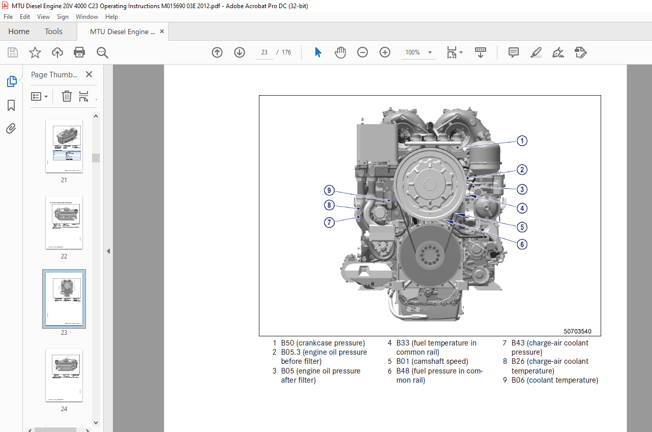
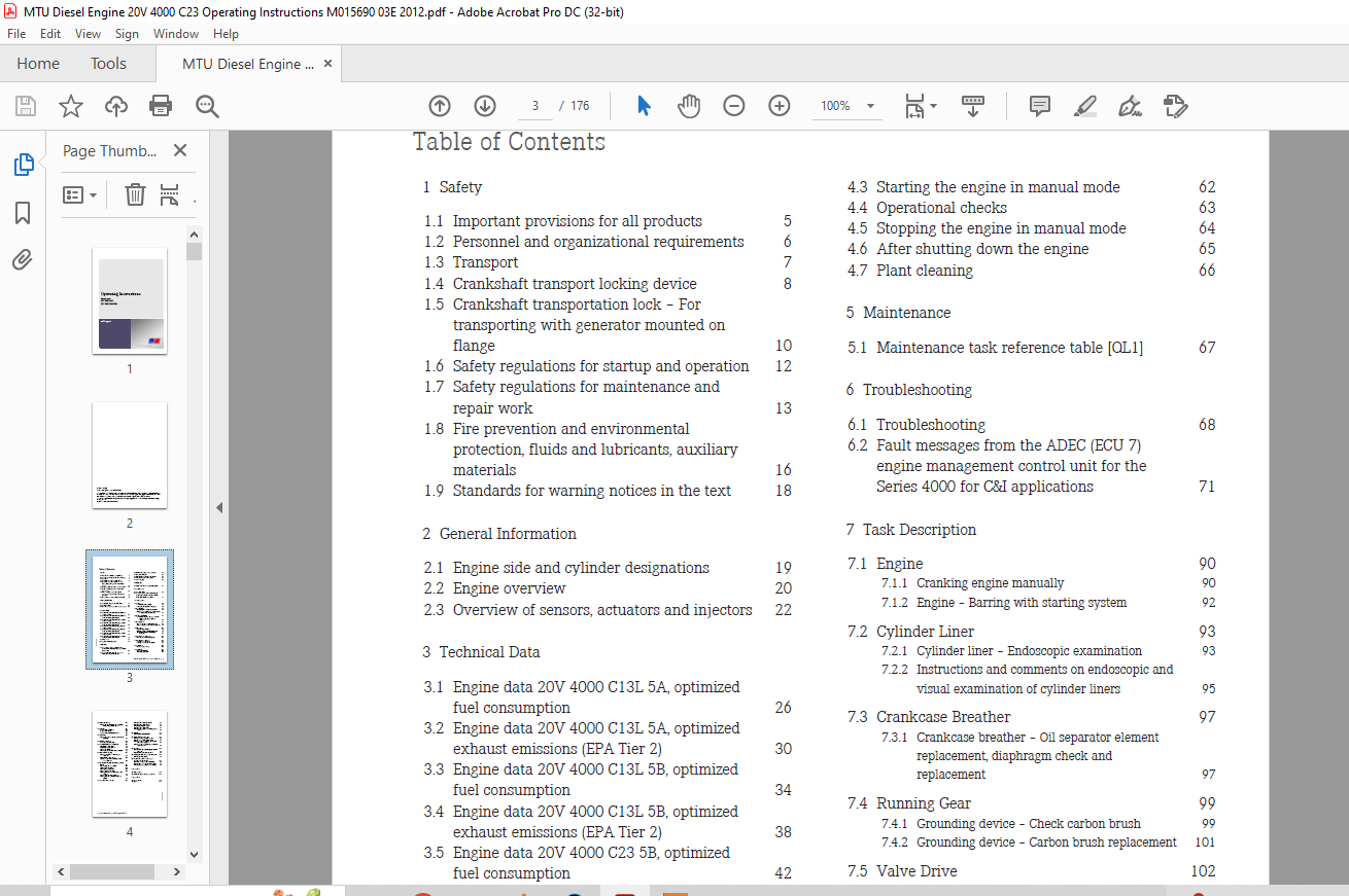
TABLE OF CONTENTS:
MTU Diesel Engine 20 V 4000 C13L 20 V 4000 C23 C23L Operating Instructions Manual M015690-03E PDF DOWNLOAD
Operating Instructions......................................................................................................  1
	Table of Contents.......................................................................................................  3
	1 Safety................................................................................................................  5
		1.1 Important provisions for all products...........................................................................  5
		1.2 Personnel and organizational requirements.......................................................................  6
		1.3 Transport.......................................................................................................  7
		1.4 Crankshaft transport locking device.............................................................................  8
		1.5 Crankshaft transportation lock – For transporting with generator mounted on flange.............................. 10
		1.6 Safety regulations for startup and operation.................................................................... 12
		1.7 Safety regulations for maintenance and repair work.............................................................. 13
		1.8 Fire prevention and environmental protection, fluids and lubricants, auxiliary materials........................ 16
		1.9 Standards for warning notices in the text....................................................................... 18
	2 General Information................................................................................................... 19
		2.1 Engine side and cylinder designations........................................................................... 19
		2.2 Engine overview................................................................................................. 20
		2.3 Overview of sensors, actuators and injectors.................................................................... 22
	3 Technical Data........................................................................................................ 26
		3.1 Engine data 20V 4000 C13L 5A, optimized fuel consumption........................................................ 26
		3.2 Engine data 20V 4000 C13L 5A, optimized exhaust emissions (EPA Tier 2).......................................... 30
		3.3 Engine data 20V 4000 C13L 5B, optimized fuel consumption........................................................ 34
		3.4 Engine data 20V 4000 C13L 5B, optimized exhaust emissions (EPA Tier 2).......................................... 38
		3.5 Engine data 20V 4000 C23 5B, optimized fuel consumption......................................................... 42
		3.6 Engine data 20V 4000 C23 5B, optimized exhaust emissions (EPA Tier 2)........................................... 46
		3.7 Engine data 20V 4000 C23L 5B, optimized fuel consumption........................................................ 50
		3.8 Engine data 20V 4000 C23L 5B, optimized exhaust emissions (EPA Tier 2).......................................... 54
		3.9 Firing order.................................................................................................... 58
		3.10 Engine – Main dimensions....................................................................................... 59
	4 Operation............................................................................................................. 60
		4.1 Preparations for recommissioning the engine after extended out-of-service periods (>3 months)................... 60
		4.2 Putting the engine into operation after scheduled out-of-service-period......................................... 61
		4.3 Starting the engine in manual mode.............................................................................. 62
		4.4 Operational checks.............................................................................................. 63
		4.5 Stopping the engine in manual mode.............................................................................. 64
		4.6 After shutting down the engine.................................................................................. 65
		4.7 Plant cleaning.................................................................................................. 66
	5 Maintenance........................................................................................................... 67
		5.1 Maintenance task reference table [QL1].......................................................................... 67
	6 Troubleshooting....................................................................................................... 68
		6.1 Troubleshooting................................................................................................. 68
		6.2 Fault messages from the ADEC (ECU 7) engine management control unit for the Series 4000 for C&I applications.... 71
	7 Task Description...................................................................................................... 90
		7.1 Engine.......................................................................................................... 90
			7.1.1 Cranking engine manually.................................................................................. 90
			7.1.2 Engine – Barring with starting system..................................................................... 92
		7.2 Cylinder Liner.................................................................................................. 93
			7.2.1 Cylinder liner – Endoscopic examination................................................................... 93
			7.2.2 Instructions and comments on endoscopic and visual examination of cylinder liners......................... 95
		7.3 Crankcase Breather.............................................................................................. 97
			7.3.1 Crankcase breather – Oil separator element replacement, diaphragm check and replacement................... 97
		7.4 Running Gear.................................................................................................... 99
			7.4.1 Grounding device – Check carbon brush..................................................................... 99
			7.4.2 Grounding device – Carbon brush replacement...............................................................101
		7.5 Valve Drive.....................................................................................................102
			7.5.1 Valve gear – Lubrication..................................................................................102
			7.5.2 Valve clearance – Check and adjustment....................................................................103
			7.5.3 Cylinder head cover – Removal and installation............................................................105
		7.6 Injection Pump / HP Pump........................................................................................106
			7.6.1 HP pump – Filling with engine oil.........................................................................106
		7.7 Injection Valve / Injector......................................................................................107
			7.7.1 Injector – Replacement....................................................................................107
			7.7.2 Injector – Removal and installation.......................................................................108
		7.8 Fuel System.....................................................................................................113
			7.8.1 Fuel system – Venting.....................................................................................113
		7.9 Fuel Filter.....................................................................................................114
			7.9.1 Replacing fuel filter.....................................................................................114
			7.9.2 Draining fuel prefilter...................................................................................115
		7.10 Charge-Air Cooling.............................................................................................116
			7.10.1 Intercooler – Checking condensate drain for coolant discharge and obstructions...........................116
		7.11 Air Filter.....................................................................................................117
			7.11.1 Air filter – Replacement.................................................................................117
			7.11.2 Air filter – Check.......................................................................................118
			7.11.3 Air filter – Removal and installation....................................................................119
		7.12 Air Intake.....................................................................................................120
			7.12.1 Service indicator – Signal ring position check (optional)................................................120
		7.13 Starting Equipment.............................................................................................121
			7.13.1 Starter – Condition check................................................................................121
		7.14 Lube Oil System, Lube Oil Circuit..............................................................................122
			7.14.1 Checking engine oil level................................................................................122
			7.14.2 Checking engine oil level................................................................................123
			7.14.3 Engine oil – Change......................................................................................124
			7.14.4 Engine oil – Sample extraction and analysis..............................................................126
		7.15 Oil Filtration / Cooling.......................................................................................127
			7.15.1 Automatic oil filter – Oil filter candles replacement....................................................127
			7.15.2 Oil indicator filter – Check.............................................................................130
			7.15.3 Centrifugal oil filter – Cleaning and filter-sleeve replacement..........................................132
		7.16 Coolant Circuit, General, High-Temperature Circuit.............................................................134
			7.16.1 Engine coolant – Level check.............................................................................134
			7.16.2 Engine coolant – Change..................................................................................135
			7.16.3 Draining engine coolant..................................................................................136
			7.16.4 Topping up engine coolant................................................................................138
			7.16.5 Engine coolant pump – Checking pressure relief port......................................................141
			7.16.6 Engine coolant filter – Replacement......................................................................142
			7.16.7 Engine coolant – Sample extraction and analysis..........................................................143
		7.17 Low-Temperature Circuit........................................................................................144
			7.17.1 Charge-air coolant – Level check.........................................................................144
			7.17.2 Charge-air coolant – Change..............................................................................145
			7.17.3 Draining charge-air coolant..............................................................................146
			7.17.4 Charge-air coolant – Filling.............................................................................147
			7.17.5 Charge-air coolant pump – Checking pressure relief port..................................................150
		7.18 Belt Drive.....................................................................................................151
			7.18.1 Drive belt – Condition check.............................................................................151
		7.19 Battery-Charging Generator.....................................................................................152
			7.19.1 Battery-charging generator – Check.......................................................................152
			7.19.2 Alternator – Removing and refitting......................................................................153
			7.19.3 Battery-charging generator – Drive belt and belt tensioner replacement...................................155
			7.19.4 Battery-charging generator drive – Drive belt tension adjustment.........................................157
		7.20 Fan Drive......................................................................................................158
			7.20.1 Fan drive system – Checking/adjusting drive belt tension.................................................158
			7.20.2 Fan drive – Drive belt replacement.......................................................................160
		7.21 Wiring (General) for Engine/Gearbox/Unit.......................................................................161
			7.21.1 Engine wiring – Check....................................................................................161
		7.22 Accessories for (Electronic) Engine Governor / Control System..................................................162
			7.22.1 CDC parameters – Reset with DiaSys®......................................................................162
			7.22.2 Engine governor plug connections – Check.................................................................163
			7.22.3 Engine governor and connectors – Cleaning................................................................164
	8 Appendix A............................................................................................................165
		8.1 Abbreviations...................................................................................................165
		8.2 MTU contact persons/service partners............................................................................167
	9 Appendix B............................................................................................................168
		9.1 Special Tools...................................................................................................168
		9.2 Index...........................................................................................................175
DESCRIPTION:
MTU Diesel Engine 20 V 4000 C13L 20 V 4000 C23 C23L Operating Instructions Manual M015690-03E PDF DOWNLOAD
SAFETY INSTRUCTIONS:
Important Provisions for All Products
NameplateThe product is identified by a nameplate, model designation, or serial number, and it must match the information on the title page of this manual. The nameplate, model designation, or serial number can be found on the product.General InformationThis product may pose a risk of injury or damage in the following cases:
- Incorrect use
- Operation, maintenance, and repair by unqualified personnel
- Modifications or conversions
- Noncompliance with the safety instructions and warning notices
Correct UseThe product is intended exclusively for the application specified in the contract or defined at the time of delivery. This means that the equipment must be operated:
- Within the permissible operating parameters in accordance with the product data
- With fluids and lubricants approved by the manufacturer in accordance with Fluids and Lubricants Specifications of the manufacturer
- With spare parts approved by the manufacturer in accordance with the applicable Spare Parts Catalog
- In the original as-delivered configuration or in a configuration approved by the manufacturer in writing (including engine control/parameters)
- In compliance with all safety instructions and in adherence to all warning notices in this manual
- In accordance with the maintenance requirements over the entire service life of the product (Maintenance Schedule)
- In compliance with the maintenance and repair instructions contained in this manual, in particular with regard to the specified tightening torques
- With the exclusive use of technical personnel trained in commissioning, operation, maintenance, and repair
- By contracting only workshops authorized by the manufacturer to carry out repair and overhaul
Any other use is considered improper use and increases the risk of personnel injury or material damage in product operation. The manufacturer will accept no liability for such damage.Modifications or ConversionsUnauthorized modifications to the product compromise safety. The manufacturer will accept no liability or warranty claims for any damage caused by unauthorized modifications or conversions.Spare PartsOnly genuine spare parts must be used to replace components or assemblies. The manufacturer will accept no liability or warranty claims for any damage caused by the use of other spare parts.
More products