$35
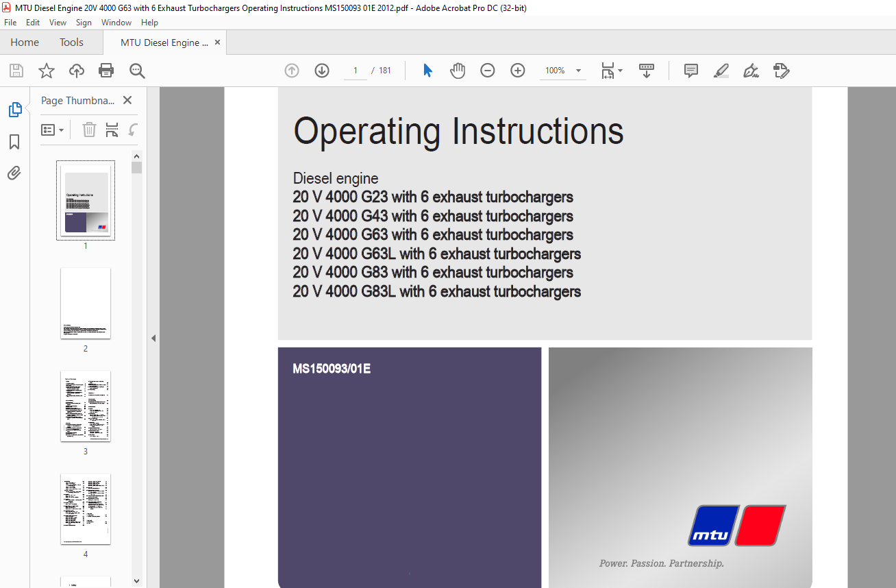
MTU Diesel Engine 20 V 4000 G23 (with 6 exhaust turbochargers)Operating Instruction Manual PDF
MTU Diesel Engine 20 V 4000 G23 (with 6 exhaust turbochargers) 20 V 4000 G24(with 6 exhaust turbochargers) 20 V 4000 G63(with 6 exhaust turbochargers) 20 V 4000 G63L(with 6 exhaust turbochargers) 20 V 4000 G83(with 6 exhaust turbochargers) 20 V 4000 G83L (with 6 exhaust turbochargers) Operating Instruction Manual PDF DOWNLOAD
FILE DETAILS:
MTU Diesel Engine 20 V 4000 G23 (with 6 exhaust turbochargers) 20 V 4000 G24(with 6 exhaust turbochargers) 20 V 4000 G63(with 6 exhaust turbochargers) 20 V 4000 G63L(with 6 exhaust turbochargers) 20 V 4000 G83(with 6 exhaust turbochargers) 20 V 4000 G83L (with 6 exhaust turbochargers) Operating Instruction Manual PDF DOWNLOAD
Language : English
Pages : 181
Downloadable : Yes
File Type : PDF
IMAGES PREVIEW OF THE MANUAL:

DESCRIPTION:
MTU Diesel Engine 20 V 4000 G23 (with 6 exhaust turbochargers) 20 V 4000 G24(with 6 exhaust turbochargers) 20 V 4000 G63(with 6 exhaust turbochargers) 20 V 4000 G63L(with 6 exhaust turbochargers) 20 V 4000 G83(with 6 exhaust turbochargers) 20 V 4000 G83L (with 6 exhaust turbochargers) Operating Instruction Manual PDF DOWNLOAD
SAFETY:
General ConditionsGeneral:
- In addition to the instructions in this publication, the applicable country-specific legislation and other compulsory regulations regarding accident prevention and environmental protection must be observed.
- This state-of-the-art engine has been designed to meet all applicable laws and regulations.
- The engine may nevertheless present a risk of injury or damage in the following cases:
- Incorrect use.
- Operation, maintenance, and repair by unqualified personnel.
- Modifications or conversions.
- Noncompliance with the Safety Instructions.
Correct Use:
- The engine is intended solely for use in accordance with contractual agreements and the purpose envisaged for it on delivery. Any other use is considered improper use.
- The engine manufacturer accepts no liability whatsoever for resultant damage or injury in such a case. The responsibility is borne by the user alone.
- Correct use also includes observation of and compliance with the maintenance specifications.
Modifications or Conversions:
- Unauthorized modifications to the engine represent a safety risk.
- MTU will accept no liability or warranty claims for any damage caused by unauthorized modifications or conversions.
Spare Parts:
- Only genuine MTU spare parts must be used to replace components or assemblies.
- MTU accepts no liability whatsoever for damage or injury resulting from the use of other spare parts, and the warranty shall be voided in such a case.
Reworking Components:
- Repair or engine overhaul must be carried out in workshops authorized by MTU
TABLE OF CONTENTS:
MTU Diesel Engine 20 V 4000 G23 (with 6 exhaust turbochargers) 20 V 4000 G24(with 6 exhaust turbochargers) 20 V 4000 G63(with 6 exhaust turbochargers) 20 V 4000 G63L(with 6 exhaust turbochargers) 20 V 4000 G83(with 6 exhaust turbochargers) 20 V 4000 G83L (with 6 exhaust turbochargers) Operating Instruction Manual PDF DOWNLOAD
Operating Instructions..............................................................................................  1
	Table of Contents...............................................................................................  3
	1 Safety........................................................................................................  5
		1.1 General conditions......................................................................................  5
		1.2 Personnel and organizational requirements...............................................................  6
		1.3 Transport...............................................................................................  7
		1.4 Crankshaft transport locking device.....................................................................  8
		1.5 Explosion hazard when removing inspection port cover on engine.......................................... 11
		1.6 Safety regulations for maintenance and repair work...................................................... 12
		1.7 Auxiliary materials, fluids and lubricants, fire prevention and environmental protection................ 15
		1.8 Conventions for safety instructions in the text......................................................... 17
	2 Product Summary............................................................................................... 18
		2.1 Engine Layout........................................................................................... 18
		2.2 Overview of sensors, actuators and injectors............................................................ 19
		2.3 Engine – Main dimensions................................................................................ 23
		2.4 Firing order............................................................................................ 24
		2.5 Final compression pressure.............................................................................. 25
		2.6 Engine side and cylinder designations................................................................... 26
		2.7 20V 4000 Gx3 engine data: Continuous operation, variable 3B, optimized fuel consumption................. 27
		2.8 20V 4000 Gx3 engine data: Continuous operation, variable 3B, optimized exhaust emissions ("TA-Luft").... 32
		2.9 20 V 4000 Gx3 engine data: Standby operation 3D, optimized fuel consumption, 6ETC....................... 35
	3 Operation..................................................................................................... 40
		3.1 Putting the engine into operation after extended out-of-service periods (>3 months)..................... 40
		3.2 Putting the engine into operation after scheduled out-of-service-period................................. 41
		3.3 Start engine in manual mode (testing mode).............................................................. 42
		3.4 Safety system – Override................................................................................ 43
		3.5 Operational checks...................................................................................... 44
		3.6 Starting the engine in emergency situations (override mode)............................................. 45
		3.7 Stop engine in manual mode (testing mode)............................................................... 46
		3.8 Emergency stop.......................................................................................... 47
		3.9 After stopping the engine – Engine remains ready for operation.......................................... 48
		3.10 After stopping the engine – putting the engine out of service.......................................... 49
		3.11 Plant cleaning......................................................................................... 50
	4 Maintenance................................................................................................... 51
		4.1 Maintenance task reference table [QL1].................................................................. 51
	5 Troubleshooting............................................................................................... 52
		5.1 Troubleshooting......................................................................................... 52
		5.2 Engine governor ADEC (ECU 7) for Series 4000 genset engines – Fault messages............................ 55
	6 Task Description..............................................................................................104
		6.1 Engine..................................................................................................104
			6.1.1 Engine – Barring manually.........................................................................104
			6.1.2 Engine – Barring with starting system.............................................................105
			6.1.3 Engine – Test run.................................................................................106
		6.2 Cylinder Liner..........................................................................................107
			6.2.1 Cylinder liner – Endoscopic examination...........................................................107
			6.2.2 Cylinder liner – Instructions and comments on endoscopic and visual examination...................109
		6.3 Crankcase Breather......................................................................................111
			6.3.1 Crankcase breather – Oil mist fine separator replacement..........................................111
		6.4 Valve Drive.............................................................................................112
			6.4.1 Valve gear – Lubrication..........................................................................112
			6.4.2 Valve clearance – Check and adjustment............................................................113
			6.4.3 Cylinder head cover – Removal and installation....................................................117
		6.5 Injection Pump / HP Pump................................................................................118
			6.5.1 HP pump – Filling with engine oil.................................................................118
		6.6 Injection Valve / Injector..............................................................................119
			6.6.1 Injector – Replacement............................................................................119
			6.6.2 Injector – Removal and installation...............................................................120
		6.7 Fuel System.............................................................................................125
			6.7.1  Fuel system – Venting............................................................................125
		6.8 Fuel Filter.............................................................................................126
			6.8.1 Fuel filter – Replacement.........................................................................126
			6.8.2 Fuel prefilter cleaning...........................................................................127
			6.8.3 Fuel prefilter – Differential pressure gauge check and adjustment.................................128
			6.8.4 Fuel prefilter – Draining.........................................................................129
			6.8.5 Fuel prefilter ‒ Flushing.........................................................................130
			6.8.6 Fuel prefilter – Filter element replacement.......................................................132
		6.9 Charge-Air Cooling......................................................................................134
			6.9.1 Intercooler – Checking condensate drain for coolant discharge and obstructions....................134
		6.10 Air Filter.............................................................................................135
			6.10.1 Air filter – Replacement.........................................................................135
			6.10.2 Air filter – Check...............................................................................136
			6.10.3 Air filter – Removal and installation............................................................137
		6.11 Air Intake.............................................................................................138
			6.11.1 Contamination indicator – Signal ring position check (optional)..................................138
		6.12 Starting Equipment.....................................................................................139
			6.12.1 Air starter – Manual operation...................................................................139
		6.13 Lube Oil System, Lube Oil Circuit......................................................................140
			6.13.1 Engine oil – Change..............................................................................140
			6.13.2 Engine oil level – Check.........................................................................142
			6.13.3 Engine oil – Sample extraction and analysis......................................................143
		6.14 Oil Filtration / Cooling...............................................................................144
			6.14.1 Engine oil filter – Replacement..................................................................144
			6.14.2 Centrifugal oil filter – Cleaning and filter sleeve replacement..................................145
		6.15 Coolant Circuit, General, High-Temperature Circuit.....................................................147
			6.15.1 Engine coolant – Level check.....................................................................147
			6.15.2 Engine coolant – Change..........................................................................148
			6.15.3 Engine coolant – Draining........................................................................149
			6.15.4 Engine coolant – Filling.........................................................................150
			6.15.5 Engine coolant pump – Relief bore check..........................................................153
			6.15.6 Engine coolant – Sample extraction and analysis..................................................154
		6.16 Low-Temperature Circuit................................................................................155
			6.16.1 Charge-air coolant – Level check.................................................................155
			6.16.2 Charge-air coolant – Change......................................................................156
			6.16.3  Charge-air coolant – Draining...................................................................157
			6.16.4  Charge-air coolant – Filling....................................................................158
			6.16.5 Charge-air coolant pump – Relief bore check......................................................161
		6.17 Belt Drive.............................................................................................162
			6.17.1 Drive belt – Condition check.....................................................................162
		6.18 Battery-Charging Generator.............................................................................163
			6.18.1 Battery-charging generator drive – Drive belt tension adjustment.................................163
			6.18.2 Battery-charging generator drive – Drive belt replacement........................................164
		6.19 Wiring (General) for Engine/Gearbox/Unit...............................................................165
			6.19.1 Engine wiring – Check............................................................................165
		6.20 Engine Mounting / Support..............................................................................166
			6.20.1 Engine mounting – Check..........................................................................166
		6.21 Accessories for (Electronic) Engine Governor / Control System..........................................167
			6.21.1 CDC parameters – Reset with DiaSys®..............................................................167
			6.21.2 Engine governor and connectors – Cleaning........................................................168
			6.21.3 Engine governor – Checking plug-in connections...................................................169
			6.21.4 ECU 7 engine governor – Removal and installation.................................................170
	7 Appendix A....................................................................................................171
		7.1 Abbreviations...........................................................................................171
		7.2 MTU contacts/service partners...........................................................................174
	8 Appendix B....................................................................................................175
		8.1 Special Tools...........................................................................................175
		8.2 Index...................................................................................................180

