$45
MTU Diesel Engine V 4000 M70, V 4000 M71 Operating Instructions Manual M015412-03E PDF DOWNLOAD
MTU Diesel Engine V 4000 M70, V 4000 M71 Operating Instructions Manual M015412-03E PDF DOWNLOAD
FILE DETAILS:
MTU Diesel Engine V 4000 M70, V 4000 M71 Operating Instructions Manual M015412-03E PDF DOWNLOAD
Language : English
Pages : 204
Downloadable : Yes
File Type : PDF
IMAGES PREVIEW OF THE MANUAL:
VIDEO PREVIEW:
TABLE OF CONTENTS:
MTU Diesel Engine V 4000 M70, V 4000 M71 Operating Instructions Manual M015412-03E PDF DOWNLOAD
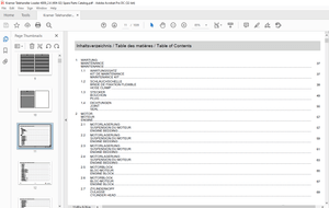
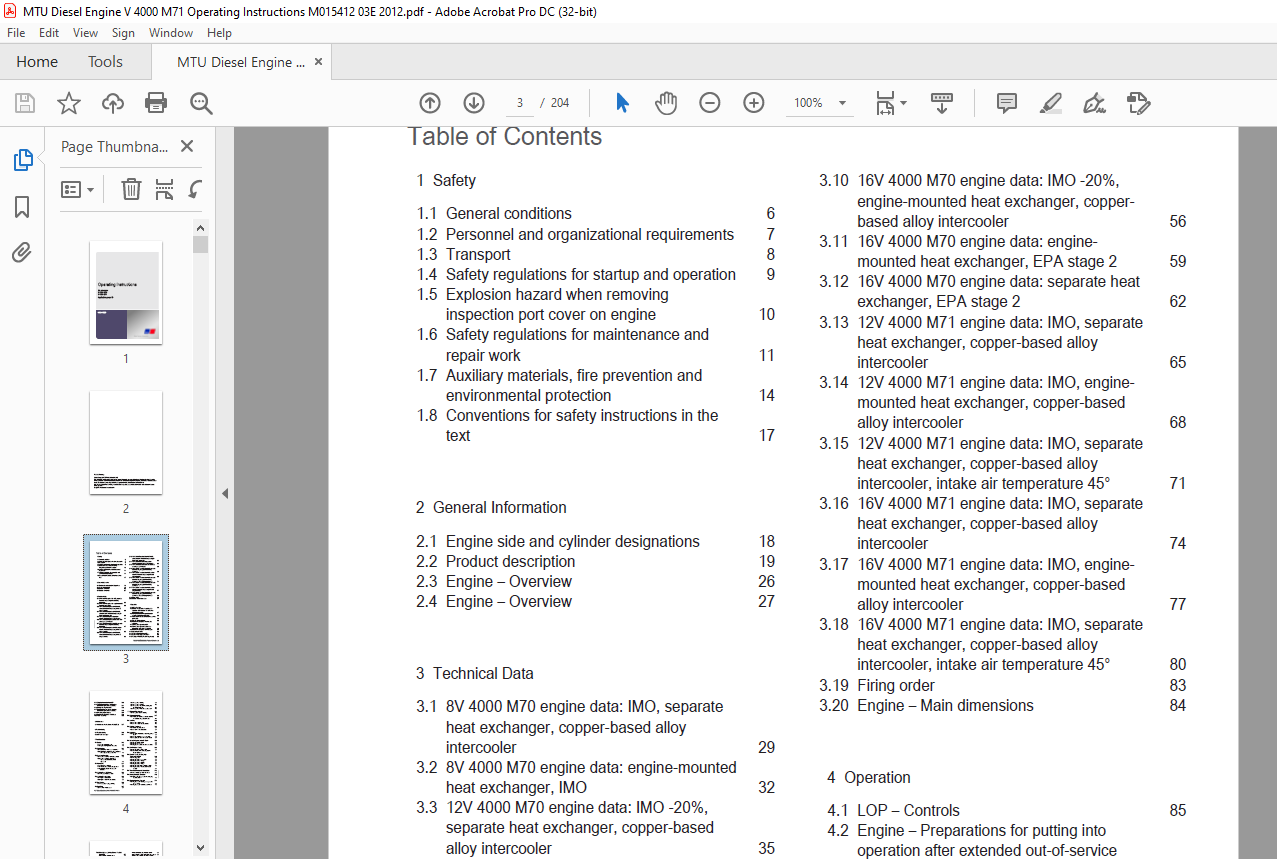
Operating Instructions.............................................................................................................  1
	Table of Contents..............................................................................................................  3
	1 Safety.......................................................................................................................  6
		1.1 General conditions.....................................................................................................  6
		1.2 Personnel and organizational requirements..............................................................................  7
		1.3 Transport..............................................................................................................  8
		1.4 Safety regulations for startup and operation...........................................................................  9
		1.5 Explosion hazard when removing inspection port cover on engine......................................................... 10
		1.6 Safety regulations for maintenance and repair work..................................................................... 11
		1.7 Auxiliary materials, fire prevention and environmental protection...................................................... 14
		1.8 Conventions for safety instructions in the text........................................................................ 17
	2 General Information.......................................................................................................... 18
		2.1 Engine side and cylinder designations.................................................................................. 18
		2.2 Product description.................................................................................................... 19
		2.3 Engine – Overview...................................................................................................... 26
		2.4 Engine – Overview...................................................................................................... 27
	3 Technical Data............................................................................................................... 29
		3.1 8V 4000 M70 engine data: IMO, separate heat exchanger, copper-based alloy intercooler.................................. 29
		3.2 8V 4000 M70 engine data: engine-mounted heat exchanger, IMO............................................................ 32
		3.3 12V 4000 M70 engine data: IMO -20%, separate heat exchanger, copper-based alloy intercooler............................ 35
		3.4 12V 4000 M70 engine data: IMO -20%, engine-mounted heat exchanger, copper-based alloy intercooler...................... 38
		3.5 12V 4000 M70 engine data: engine-mounted heat exchanger, EPA stage 2................................................... 41
		3.6 12V 4000 M70 engine data: separate heat exchanger, EPA stage 2......................................................... 44
		3.7 16V 4000 M70 engine data: IMO, separate heat exchanger, copper-based alloy intercooler................................. 47
		3.8 16V 4000 M70 engine data: IMO, engine-mounted heat exchanger, copper-based alloy intercooler........................... 50
		3.9 16V 4000 M70 engine data: IMO -20%, separate heat exchanger, copper-based alloy intercooler............................ 53
		3.10 16V 4000 M70 engine data: IMO -20%, engine-mounted heat exchanger, copper-based alloy intercooler..................... 56
		3.11 16V 4000 M70 engine data: engine-mounted heat exchanger, EPA stage 2.................................................. 59
		3.12 16V 4000 M70 engine data: separate heat exchanger, EPA stage 2........................................................ 62
		3.13 12V 4000 M71 engine data: IMO, separate heat exchanger, copper-based alloy intercooler................................ 65
		3.14 12V 4000 M71 engine data: IMO, engine-mounted heat exchanger, copper-based alloy intercooler.......................... 68
		3.15 12V 4000 M71 engine data: IMO, separate heat exchanger, copper-based alloy intercooler, intake air temperature 45°.... 71
		3.16 16V 4000 M71 engine data: IMO, separate heat exchanger, copper-based alloy intercooler................................ 74
		3.17 16V 4000 M71 engine data: IMO, engine-mounted heat exchanger, copper-based alloy intercooler.......................... 77
		3.18 16V 4000 M71 engine data: IMO, separate heat exchanger, copper-based alloy intercooler, intake air temperature 45°.... 80
		3.19 Firing order.......................................................................................................... 83
		3.20 Engine – Main dimensions.............................................................................................. 84
	4 Operation.................................................................................................................... 85
		4.1 LOP – Controls......................................................................................................... 85
		4.2 Engine – Preparations for putting into operation after extended out-of-service periods (>3 months)..................... 87
		4.3 Putting the engine into operation after scheduled out-of-service-period................................................ 88
		4.4 Tasks after extended out-of-service periods (>3 weeks)................................................................. 89
		4.5 Checks prior to start-up............................................................................................... 90
		4.6 Fuel treatment system – Putting into operation......................................................................... 91
		4.7 Starting the engine from LOP........................................................................................... 93
		4.8 Starting the engine at the BlueLine automation system (control stand).................................................. 94
		4.9 Fuel treatment system – Switching on................................................................................... 95
		4.10 Operational checks.................................................................................................... 96
		4.11 Clutch – Engaging from LOP............................................................................................ 97
		4.12 Clutch – Disengaging from LOP......................................................................................... 98
		4.13 Waterjet – Flushing from LOP (optional)............................................................................... 99
		4.14 Stopping the engine from LOP..........................................................................................100
		4.15 Stopping the engine at the BlueLine automation system (control stand).................................................101
		4.16 Emergency stop from LOP...............................................................................................102
		4.17 Engine emergency stop at BlueLine automation system (control stand)...................................................103
		4.18 After stopping the engine.............................................................................................104
		4.19 Fuel treatment system – Shutdown......................................................................................105
		4.20 Plant – Cleaning......................................................................................................106
	5 Maintenance..................................................................................................................107
		5.1 Maintenance task reference table [QL1].................................................................................107
	6 Troubleshooting..............................................................................................................108
		6.1 Troubleshooting........................................................................................................108
		6.2 LOP fault messages.....................................................................................................111
	7 Task Description.............................................................................................................112
		7.1 Engine.................................................................................................................112
			7.1.1 Engine – Barring manually........................................................................................112
			7.1.2 Engine – Barring with starting system............................................................................113
		7.2 Cylinder Liner.........................................................................................................114
			7.2.1 Cylinder liner – Endoscopic examination..........................................................................114
			7.2.2 Cylinder liner – Instructions and comments on endoscopic and visual examination..................................116
		7.3 Crankcase Breather.....................................................................................................118
			7.3.1 Crankcase breather – Oil separator check.........................................................................118
			7.3.2 Crankcase breather – Oil separator replacement, diaphragm check and replacement..................................119
		7.4 Valve Drive............................................................................................................121
			7.4.1 Valve gear - Lubrication.........................................................................................121
			7.4.2 Valve clearance – Check and adjustment...........................................................................122
			7.4.3 Cylinder head cover – Removal and installation...................................................................127
		7.5 Injection Pump / HP Pump...............................................................................................128
			7.5.1 HP pump – Relief bore check......................................................................................128
		7.6 Injection Valve / Injector.............................................................................................129
			7.6.1 Injector – Replacement...........................................................................................129
			7.6.2 Injector – Removal and installation..............................................................................130
		7.7 Fuel System............................................................................................................135
			7.7.1 Fuel system – Venting and filling................................................................................135
		7.8 Fuel Filter............................................................................................................137
			7.8.1 Fuel filter – Replacement........................................................................................137
			7.8.2 Fuel prefilter – Draining........................................................................................139
			7.8.3 Fuel prefilter ‒ Flushing........................................................................................140
			7.8.4 Fuel prefilter – Differential pressure gauge check and adjustment................................................142
			7.8.5 Fuel prefilter – Filter element replacement......................................................................143
		7.9 Exhaust Turbocharger...................................................................................................145
			7.9.1 Compressor wheel – Cleaning......................................................................................145
		7.10 Charge-Air Cooling....................................................................................................147
			7.10.1 Intercooler – Checking condensate drain line for coolant discharge and obstruction..............................147
		7.11 Air Filter............................................................................................................148
			7.11.1 Air filter – Replacement........................................................................................148
			7.11.2 Air filter – Removal and installation...........................................................................149
		7.12 Starting Equipment....................................................................................................150
			7.12.1 Starter – Condition check.......................................................................................150
			7.12.2 Air starter – Manual operation..................................................................................151
		7.13 Air Intake............................................................................................................152
			7.13.1 Contamination indicator – Signal ring position check............................................................152
			7.13.2 Air flap – Check for ease of movement...........................................................................153
			7.13.3 Air pipework from air filter to ETC – Check.....................................................................154
		7.14 Lube Oil System, Lube Oil Circuit.....................................................................................155
			7.14.1 Engine oil level – Check........................................................................................155
			7.14.2 Engine oil – Change.............................................................................................156
			7.14.3 Engine oil – Sample extraction and analysis.....................................................................158
		7.15 Oil Filtration / Cooling..............................................................................................159
			7.15.1 Engine oil filter – Replacement.................................................................................159
			7.15.2 Centrifugal oil filter – Cleaning and filter sleeve replacement.................................................161
		7.16 Coolant Circuit, General, High-Temperature Circuit....................................................................163
			7.16.1 Venting points..................................................................................................163
			7.16.2 Engine coolant – Level check....................................................................................164
			7.16.3 Engine coolant – Change.........................................................................................165
			7.16.4 Engine coolant – Draining.......................................................................................166
			7.16.5 Engine coolant – Filling........................................................................................167
			7.16.6 Engine coolant pump – Relief bore check.........................................................................170
			7.16.7 Engine coolant – Sample extraction and analysis.................................................................171
		7.17 Raw Water Pump with Connections.......................................................................................172
			7.17.1 Raw water pump – Relief bore check..............................................................................172
		7.18 Battery-Charging Generator............................................................................................173
			7.18.1 Battery-charging generator drive – Coupling condition check.....................................................173
		7.19 Engine Mounting / Support.............................................................................................174
			7.19.1 Engine mounts – Checking securing screws for firm seating.......................................................174
			7.19.2 Engine mounts – Resilient element check.........................................................................175
		7.20 Drive Systems, Driving End and Free End (Coupling)....................................................................177
			7.20.1 Coupling – Condition check......................................................................................177
		7.21 Auxiliary PTO.........................................................................................................178
			7.21.1 Bilge pump – Relief bore check..................................................................................178
		7.22 Fuel Supply System....................................................................................................179
			7.22.1 Water drain valve – Check.......................................................................................179
			7.22.2 Differential pressure gauge – Check.............................................................................180
			7.22.3 Water level probe (3-in-1 rod electrode) – Check................................................................181
			7.22.4 Pump capacity – Check...........................................................................................182
			7.22.5 Coalescer filter element – Replacement..........................................................................183
		7.23 Wiring (General) for Engine/Gearbox/Unit..............................................................................185
			7.23.1 Engine wiring – Check...........................................................................................185
		7.24 Accessories for (Electronic) Engine Governor / Control System.........................................................186
			7.24.1 Engine governor and connectors – Cleaning.......................................................................186
			7.24.2 Engine monitoring unit and connectors – Cleaning................................................................187
			7.24.3 Limit switch for start interlock ‒ Check........................................................................188
			7.24.4 Checking engine control unit plug connections...................................................................189
			7.24.5 Engine monitoring unit – Plug connection check..................................................................190
			7.24.6 Engine control unit – Removal and installation..................................................................191
			7.24.7 LOP – Visual inspection.........................................................................................193
	8 Appendix A...................................................................................................................195
		8. Abbreviations...........................................................................................................  0
		8. MTU contacts/service partners...........................................................................................  0
	9 Appendix B...................................................................................................................198
		9.1 Special Tools..........................................................................................................198
		9.2 Index..................................................................................................................202
DESCRIPTION:
MTU Diesel Engine V 4000 M70, V 4000 M71 Operating Instructions Manual M015412-03E PDF DOWNLOAD
SAFETY:
General Conditions
General
In addition to the instructions in this publication, the applicable country-specific legislation and other compulsory regulations regarding accident prevention and environmental protection must be observed. This state-of-the-art engine has been designed to meet all applicable laws and regulations. The engine may nevertheless present a risk of injury or damage in the following cases:
- Incorrect use
- Operation, maintenance, and repair by unqualified personnel
- Modifications or conversions
- Noncompliance with the Safety Instructions
Correct UseThe engine is intended solely for use in accordance with contractual agreements and the purpose envisaged for it on delivery. Any other use is considered improper use. The engine manufacturer accepts no liability whatsoever for resultant damage or injury in such case. The responsibility is borne by the user alone.Correct use also includes observation of and compliance with the operating instructions and maintenance and repair specifications.Modifications or ConversionsUnauthorized modifications to the engine represent a safety risk. MTU will accept no liability or warranty claims for any damage caused by unauthorized modifications or conversions.Spare PartsOnly genuine MTU spare parts must be used to replace components or assemblies. MTU accepts no liability whatsoever for damage or injury resulting from the use of other spare parts, and the warranty shall be voided in such case.Reworking ComponentsRepair or engine overhaul must be carried out in workshops authorized by MTU.
More products