$40
MTU Diesel Engines 12V2000G65 G65-TB 18V2000G65 G65-TB Operating Instructions Manual PDF
MTU Diesel Engines 12V2000G65 G65-TB 16V2000G65 G65-TB 18V2000G65 G65-TB Operating Instructions Manual MS15018-03E PDF DOWNLOAD
FILE DETAILS:
MTU Diesel Engines 12V2000G65 G65-TB 16V2000G65 G65-TB 18V2000G65 G65-TB Operating Instructions Manual MS15018-03E PDF DOWNLOAD
Language : English
Pages : 155
Downloadable : Yes
File Type : PDF
IMAGES PREVIEW OF THE MANUAL:
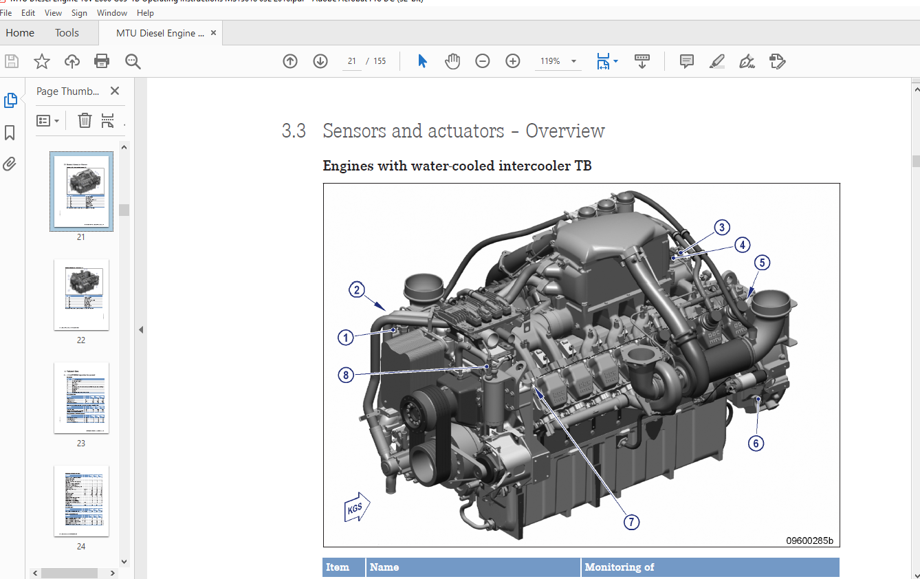
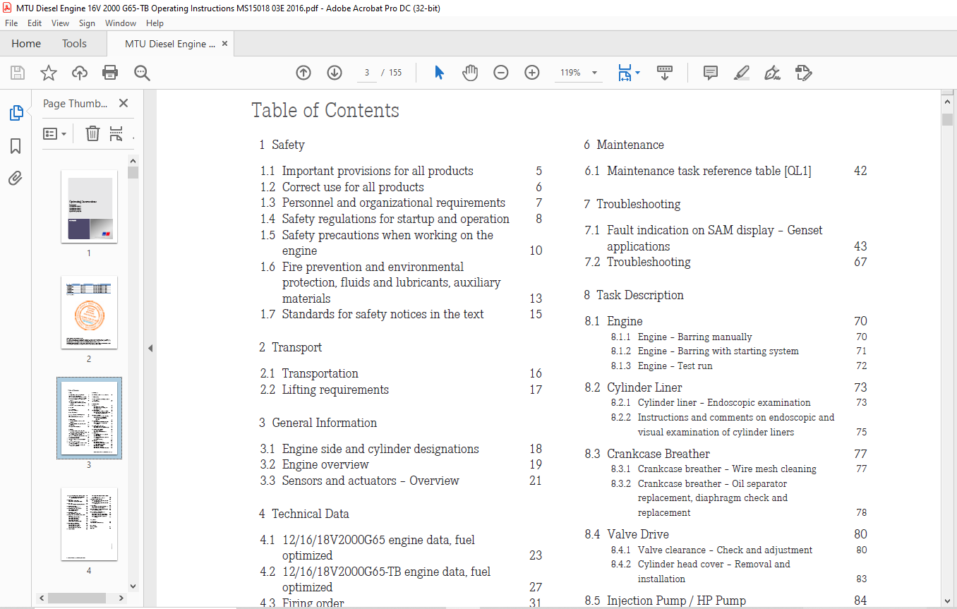
TABLE OF CONTENTS:
MTU Diesel Engines 12V2000G65 G65-TB 16V2000G65 G65-TB 18V2000G65 G65-TB Operating Instructions Manual MS15018-03E PDF DOWNLOAD
Operating Instructions
Diesel engine
12V2000G65, G65-TB
16V2000G65, G65-TB
18V2000G65, G65-TB
Application group 3A
Table of Contents
1 Safety
1.1 Important provisions for all products 5
1.2 Correct use for all products 6
1.3 Personnel and organizational requirements 7
1.4 Safety regulations for startup and operation 8
1.5 Safety precautions when working on the
engine 10
1.6 Fire prevention and environmental
protection, fluids and lubricants, auxiliary
materials 13
1.7 Standards for safety notices in the text 15
2 Transport
2.1 Transportation 16
2.2 Lifting requirements 17
3 General Information
3.1 Engine side and cylinder designations 18
3.2 Engine overview 19
3.3 Sensors and actuators – Overview 21
4 Technical Data
4.1 12/16/18V2000G65 engine data, fuel
optimized 23
4.2 12/16/18V2000G65-TB engine data, fuel
optimized 27
4.3 Firing order 31
4.4 Engine – Main dimensions 32
5 Operation
5.1 Putting the engine into operation after
extended out-of-service periods (>3 months) 33
5.2 Putting the engine into operation after
scheduled out-of-service-period 34
5.3 Engine – Starting in manual mode (test run) 35
5.4 Safety system – Override 36
5.5 Operational monitoring 37
5.6 Engine – Stopping in manual mode (test
run) 38
5.7 Engine – Emergency stop 39
5.8 After stopping the engine – Engine remains
ready for operation 40
5.9 After stopping the engine – Putting the
engine out of operation 41
6 Maintenance
6.1 Maintenance task reference table [QL1] 42
7 Troubleshooting
7.1 Fault indication on SAM display – Genset
applications 43
7.2 Troubleshooting 67
8 Task Description
8.1 Engine 70
8.1.1 Engine – Barring manually 70
8.1.2 Engine – Barring with starting system 71
8.1.3 Engine – Test run 72
8.2 Cylinder Liner 73
8.2.1 Cylinder liner – Endoscopic examination 73
8.2.2 Instructions and comments on endoscopic and
visual examination of cylinder liners 75
8.3 Crankcase Breather 77
8.3.1 Crankcase breather – Wire mesh cleaning 77
8.3.2 Crankcase breather – Oil separator
replacement, diaphragm check and
replacement 78
8.4 Valve Drive 80
8.4.1 Valve clearance – Check and adjustment 80
8.4.2 Cylinder head cover – Removal and
installation 83
8.5 Injection Pump / HP Pump 84
8.5.1 Injection pump – Replacement 84
8.5.2 Injection pump – Removal and installation 85
8.6 Injection Valve / Injector 88
8.6.1 Injector – Replacement 88
8.6.2 Injector – Removal and installation 89
8.7 Fuel System 94
8.7.1 Fuel injection line – Pressure pipe neck
replacement 94
8.7.2 Fuel – Draining 97
8.7.3 Fuel pressure relief valve – Removal and
installation 99
8.7.4 Fuel system – Venting 100
8.8 Fuel Filter 102
8.8.1 Fuel filter – Replacement 102
8.8.2 Fuel prefilter – Differential pressure gage
check and adjustment of gage 103
8.8.3 Fuel prefilter – Draining 104
8.8.4 Fuel prefilter – Flushing 106
8.8.5 Fuel prefilter – Cleaning 108
8.8.6 Fuel prefilter – Filter element replacement 109
MS15018/03E 2016-02 | Table of Contents | 3
DCL-ID: 0000019467 – 005
8.9 Charge-Air Cooling General, Left-Hand Side 111
8.9.1 Intercooler – Checking condensate drain for
coolant discharge and obstructions 111
8.10 Air Filter 112
8.10.1 Air filter – Replacement 112
8.10.2 Air filter – Removal and installation 113
8.11 Air Intake 114
8.11.1 Service indicator – Signal ring position check 114
8.12 Starting Equipment 115
8.12.1 Air starter – Manual operation 115
8.13 Lube Oil System, Lube Oil Circuit 116
8.13.1 Engine oil – Level check 116
8.13.2 Engine oil – Change 117
8.14 Oil Filtration / Cooling 118
8.14.1 Engine oil filter – Replacement 118
8.15 Coolant Circuit, General, High-Temperature
Circuit 119
8.15.1 Engine coolant – Level check 119
8.15.2 Engine coolant – Change 120
8.15.3 Engine coolant – Draining 121
8.15.4 Engine coolant – Filling 122
8.15.5 Coolant pump – Relief bore check 124
8.16 Low-Temperature Circuit 125
8.16.1 Charge-air coolant – Filling 125
8.16.2 Charge-air coolant – Draining 127
8.16.3 Charge-air coolant – Change 128
8.16.4 Charge-air coolant – Level check 129
8.17 Coolant System 130
8.17.1 Cooler – Checking cooler elements externally
for dirt 130
8.17.2 Cooler – Cleaning cooler elements 131
8.18 Battery-Charging Generator 132
8.18.1 Battery-charging generator drive – Drive-belt
check and adjustment 132
8.18.2 Battery-charging generator drive – Drive belt
replacement 134
8.19 Fan Drive 135
8.19.1 Fan drive – Drive-belt check and adjustment 135
8.19.2 Fan drive – Drive belt replacement 138
8.20 Wiring (General) for Engine/Gearbox/Unit 139
8.20.1 Engine cabling – Check 139
8.21 Accessories for (Electronic) Engine
Governor / Control System 140
8.21.1 Engine governor and connector – Cleaning 140
8.21.2 Engine governor plug connections – Check 141
8.21.3 Engine governor ECU 7 – Removal and
installation 142
9 Appendix A
9.1 Abbreviations 143
9.2 MTU Contact/Service Partners 146
10 Appendix B
10.1 Special Tools 147
10.2 Index 154
DESCRIPTION:
MTU Diesel Engines 12V2000G65 G65-TB 16V2000G65 G65-TB 18V2000G65 G65-TB Operating Instructions Manual MS15018-03E PDF DOWNLOAD
Safety Precautions When Working on the Engine
Safety Regulations Prior to Maintenance and Repair Work
- Have maintenance or repair work carried out by qualified and authorized personnel only.
- Allow the product to cool down to less than 50 °C (risk of explosion for oil vapors, fluids, and lubricants, risk of burning).
- Relieve pressure in fluid and lubricant systems and compressed-air lines that are to be opened. Use suitable collecting vessels of adequate capacity to catch fluids and lubricants.
- When changing the oil or working on the fuel system, ensure that the service room is adequately ventilated.
- Never carry out maintenance and repair work with the product in operation, unless:
- It is expressly permitted to do so following a written procedure.
- The product is running in the low load range and only for as long as absolutely necessary.
- Lock-out the product to preclude undesired starting, e.g.:
- Start interlock
- Key switch
- With hydraulic starting system: shut off supply line.
- Attach a “Do not operate” sign in the operating area or to control equipment.
- Disconnect the battery cables or actuate the battery isolating switch, if fitted. Lock out circuit breakers.
- Close the main valve on the compressed-air system and vent the compressed-air line when pneumatic starters are fitted.
- Disconnect the control equipment from the product.
- Use the recommended special tools or suitable equivalents when instructed to do so.
- Elastomer components (e.g. engine mounts, damping elements, couplings, and V-belts) must not be painted. They may only be installed after painting the engine or must be covered before painting work is carried out.
- The following applies to starters with copper-beryllium alloy pinions:
- Wear a respirator mask (filter class P3). Do not blow out the interior of the flywheel housing or the starter with compressed air. Clean the flywheel housing inside with a class H dust extraction device.
- Observe the safety data sheet.
Safety Regulations During Maintenance and Repair Work
- Take special care when removing ventilation or plug screws from the product.
- Release residual pressure before removing or replacing a component in the supply line. To depressurize pressurized lines, shut off the lines first, then release the residual pressure.
- Use only proper and calibrated tools. Observe the specified tightening torques during assembly or disassembly.
- Carry out work only on assemblies or plants that are properly secured.
- Make sure components or assemblies are placed on stable surfaces. Adopt suitable measures to avoid that components/tools fall down. Use the specified lifting equipment for all components.
- Never use the product as a climbing aid.
- When working high on the equipment, always use suitable ladders and work platforms. Never work on engines or components that are held in place by lifting equipment.
- Keep fuel injection lines and connections clean.
- Carry out appropriate cleaning procedures to clean and inspect components requiring special cleanness (e.g., components carrying oil, fuel, or air).
- Always seal connections with caps or covers if a line is removed or opened.
- Fit new seals when re-installing lines.
More products