$45
MTU Diesel Engines 8V2000Mx4x 10V2000Mx4 Operating Instructions Manual MS150060-04E PDF DOWNLOAD
MTU Diesel Engines 8V2000Mx4x 10V2000Mx4 Operating Instructions Manual MS150060-04E PDF DOWNLOAD
FILE DETAILS:
MTU Diesel Engines 8V2000Mx4x 10V2000Mx4 Operating Instructions Manual MS150060-04E PDF DOWNLOAD
Language : English
Pages : 156
Downloadable : Yes
File Type : PDF
IMAGES PREVIEW OF THE MANUAL:
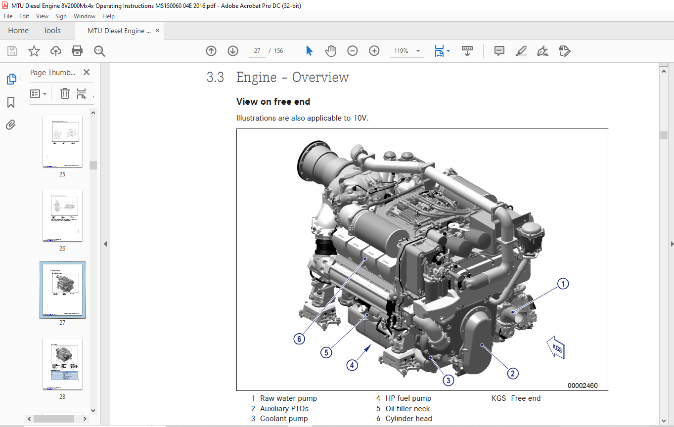
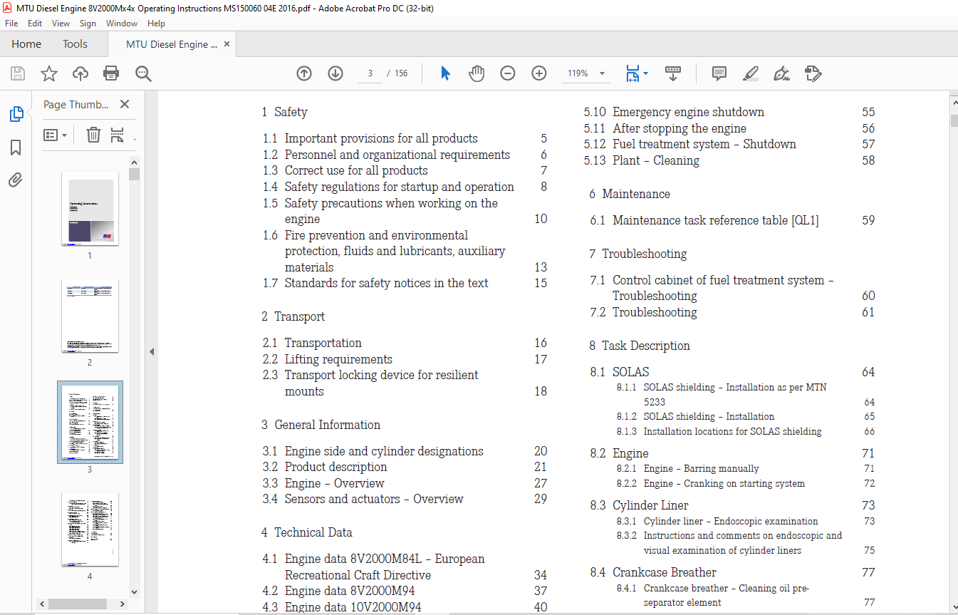
TABLE OF CONTENTS:
MTU Diesel Engines 8V2000Mx4x 10V2000Mx4 Operating Instructions Manual MS150060-04E PDF DOWNLOAD
1 Safety
1.1 Important provisions for all products 5
1.2 Personnel and organizational requirements 6
1.3 Correct use for all products 7
1.4 Safety regulations for startup and operation 8
1.5 Safety precautions when working on the
engine 10
1.6 Fire prevention and environmental
protection, fluids and lubricants, auxiliary
materials 13
1.7 Standards for safety notices in the text 15
2 Transport
2.1 Transportation 16
2.2 Lifting requirements 17
2.3 Transport locking device for resilient
mounts 18
3 General Information
3.1 Engine side and cylinder designations 20
3.2 Product description 21
3.3 Engine – Overview 27
3.4 Sensors and actuators – Overview 29
4 Technical Data
4.1 Engine data 8V2000M84L – European
Recreational Craft Directive 34
4.2 Engine data 8V2000M94 37
4.3 Engine data 10V2000M94 40
4.4 Firing order 43
4.5 Engine – Main dimensions 44
5 Operation
5.1 Putting the engine into operation after
extended out-of-service periods (>3 months) 45
5.2 Engine – Putting into operation after
scheduled out-of-service-period 46
5.3 Tasks after extended out-of-service periods
(>3 weeks) 47
5.4 Checks prior to start-up 48
5.5 Fuel treatment system – Putting into
operation 49
5.6 Operational checks 51
5.7 Fuel treatment system – Switching on 52
5.8 Starting the engine 53
5.9 Engine – Shutdown 54
5.10 Emergency engine shutdown 55
5.11 After stopping the engine 56
5.12 Fuel treatment system – Shutdown 57
5.13 Plant – Cleaning 58
6 Maintenance
6.1 Maintenance task reference table [QL1] 59
7 Troubleshooting
7.1 Control cabinet of fuel treatment system –
Troubleshooting 60
7.2 Troubleshooting 61
8 Task Description
8.1 SOLAS 64
8.1.1 SOLAS shielding – Installation as per MTN
5233 64
8.1.2 SOLAS shielding – Installation 65
8.1.3 Installation locations for SOLAS shielding 66
8.2 Engine 71
8.2.1 Engine – Barring manually 71
8.2.2 Engine – Cranking on starting system 72
8.3 Cylinder Liner 73
8.3.1 Cylinder liner – Endoscopic examination 73
8.3.2 Instructions and comments on endoscopic and
visual examination of cylinder liners 75
8.4 Crankcase Breather 77
8.4.1 Crankcase breather – Cleaning oil preseparator
element 77
8.4.2 Crankcase breather – Oil separator
replacement, diaphragm check and
replacement 78
8.5 Valve Drive 80
8.5.1 Valve clearance – Check and adjustment 80
8.5.2 Cylinder head cover – Removal and
installation 83
8.6 Injector 84
8.6.1 Injector – Replacement 84
8.6.2 Injector – Removal and installation 85
8.7 Fuel System 87
8.7.1 Fuel system – Venting 87
8.8 Fuel Filter 88
8.8.1 Fuel filter – Replacement 88
8.8.2 Fuel prefilter – Differential pressure check
and adjustment of gauge 91
8.8.3 Fuel prefilter – Draining 92
8.8.4 Fuel prefilter – Flushing 94
8.8.5 Fuel prefilter – Filter element replacement 96
8.9 Charge-Air Cooling 98
8.9.1 Charge-air cooler – Checking condensate drain
line for coolant discharge and obstruction 98
8.10 Air Filter 99
8.10.1 Air filter – Replacement 99
8.10.2 Air filter – Removal and installation 100
8.11 Air Intake 101
8.11.1 Service indicator – Signal ring position check 101
8.12 Starting Equipment 102
8.12.1 Starter – Condition check 102
8.13 Lube Oil System, Lube Oil Circuit 103
8.13.1 Engine oil – Level check 103
8.13.2 Engine oil – Change 104
8.14 Oil Filtration / Cooling 105
8.14.1 Engine oil filter – Replacement 105
8.14.2 Centrifugal oil filter and filter sleeve –
Cleaning and replacement 107
8.15 Coolant Circuit, General, High-Temperature
Circuit 110
8.15.1 Drain and venting points 110
8.15.2 Engine coolant level – Check 115
8.15.3 Engine coolant – Change 116
8.15.4 Engine coolant – Draining 117
8.15.5 Engine coolant – Filling 118
8.15.6 HT coolant pump – Relief bore check 119
8.15.7 Engine coolant sample extraction and analysis 120
8.15.8 Coolant filter – Replacement 121
8.16 Raw Water Pump with Connections 122
8.16.1 Raw water pump – Relief bore check 122
8.17 Belt Drive 123
8.17.1 Drive belt – Condition check 123
8.18 Battery-Charging Generator 124
8.18.1 Battery-charging generator drive – Drive belt
replacement 124
8.19 Fuel Supply System 125
8.19.1 Water drain valve – Check 125
8.19.2 Differential pressure gauge – Check 126
8.19.3 Water level probe (3-in-1 rod electrode) –
Check 127
8.19.4 Pump capacity – Check 128
8.19.5 Coalescer filter element – Replacement 129
8.20 Wiring (General) for Engine/Gearbox/Unit 131
8.20.1 Engine cabling – Check 131
8.21 Accessories for (Electronic) Engine
Governor / Control System 132
8.21.1 Engine governor and connector – Cleaning 132
8.21.2 EMU and connectors – Cleaning 133
8.21.3 Engine governor plug connections – Check 134
8.21.4 Engine Monitoring Unit EMU 7 – Plug
connection check 135
8.21.5 Interface module EIM plug connections –
Check 136
8.21.6 Engine Control Unit – Self-test 137
8.21.7 Engine governor ECU 7 – Removal and
installation 138
8.21.8 Engine Monitoring Unit – Removal and
installation 139
8.21.9 Engine Interface Module EIM – Removal and
installation 140
8.21.10 Diagnostic features on EIM 141
9 Appendix A
9.1 Abbreviations 144
9.2 MTU Contact/Service Partners 146
10 Appendix B
10.1 Special Tools 147
10.2 Index 154
VIDEO PREVIEW:
DESCRIPTION:
MTU Diesel Engines 8V2000Mx4x 10V2000Mx4 Operating Instructions Manual MS150060-04E PDF DOWNLOAD
SAFETY INSTRUCTIONS:
Important Provisions for All Product
Nameplate
The product is identified by a nameplate, model designation, or serial number and must match the information on the title page of this manual. The nameplate, model designation, or serial number can be found on the product.
All EU-certified engines delivered by MTU come with a second nameplate. When operating the machine in the EU: The second nameplate must be affixed in a prominent position as described in the accompanying specifications.
General InformationThis product may pose a risk of injury or damage in the following cases:
- Incorrect use
- Operation, maintenance, and repair by unqualified personnel
- Modifications or conversions
- Noncompliance with the safety instructions and warning notices
Emission Regulations and Emission LabelsResponsibility for Compliance with Emission RegulationsModification or removal of any mechanical/electronic components or the installation of additional components, including the execution of calibration processes that might affect the emission characteristics of the product, are prohibited by emission regulations. Emission control units/systems may only be maintained, exchanged, or repaired if the components used for this purpose are approved by the manufacturer.Noncompliance with these regulations will invalidate the design type approval issued by the emissions regulation authorities. The manufacturer does not accept any liability for violations of the emission regulations.The maintenance schedules of the manufacturer must be observed over the entire life cycle of the product.Replacing Components with Emission LabelsOn all MTU engines fitted with emission labels, these labels must remain on the engine throughout its operational life.Engines used exclusively in land-based, military applications other than by US government agencies are excepted from this proviso.Please note the following when replacing components with emission labels:
- The relevant emission labels must be affixed to the spare part.
- Do not transfer the emission labels from the replaced part to the spare part.
- Remove the emission labels from the replaced part and destroy them.
More products