$40
MTU Electronics Training Documentation Electronic Engine Control Technical Documentation Manual PDF
MTU Electronics Training Documentation for Electronic Engine Control Unit ECU-7 (ADEC) Technical Documentation Manual T000001-01E PDF DOWNLOAD
FILE DETAILS:
MTU Electronics Training Documentation for Electronic Engine Control Unit ECU-7 (ADEC) Technical Documentation Manual T000001-01E PDF DOWNLOAD
Language : English
Pages : 246
Downloadable : Yes
File Type : PDF
IMAGES PREVIEW OF THE MANUAL:
VIDEO PREVIEW:
DESCRIPTION:
MTU Electronics Training Documentation for Electronic Engine Control Unit ECU-7 (ADEC) Technical Documentation Manual T000001-01E PDF DOWNLOAD
The engine governor1.1 Engine governor ECU 7 – ADEC
General information
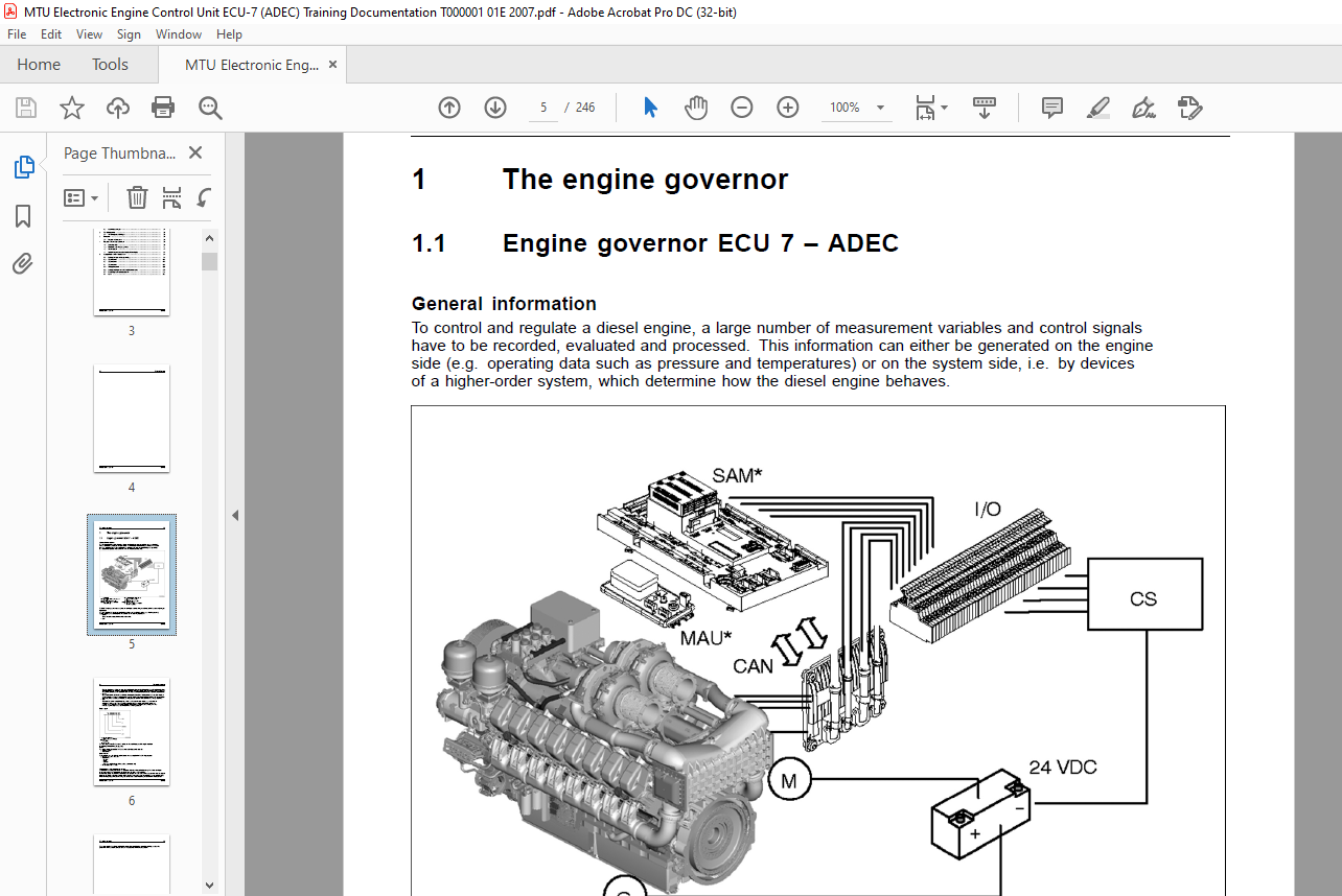
To control and regulate a diesel engine, a large number of measurement variables and control signals have to be recorded, evaluated and processed. This information can either be generated on the engine side (e.g. operating data such as pressure and temperatures) or on the system side, i.e. by devices of a higher-order system, which determine how the diesel engine behaves.
Application
The term “application” is used to describe the environment in which the engine (and thus the governor) is used. MTU engines are designed and adapted for the following applications:• Marine These are drive motors for the ship’s main drive. The engine governor Engines for railroad vehicles are used for diesel-electric drives or diesel-hydraulic drives. Diesel-electric drives are basically engines that drive a generator to produce operating voltage. This generator package is geared to the special requirements of a locomotive drive. In the case of diesel-hydraulic drives, a hydraulic pump is driven • Genset Gensets for current generation are either stationary or mobile plants. Mobile plants are used, for example, in ships for on-board power generation (marine gensets”) or in power containers for autonomous power generation. Stationary plants are used, for example, as emergency power units or in combined heat and power plants.• C&I The term C&I covers industrial engines, which can be used in many areas, e.g. excavators or off-highway dump trucks. These engines generally drive generators or hydraulic pumps in a vehicle. These engines are normally delivered to the manufacturer of these vehicles, who then have to adapt the engine and its characteristics to their application.
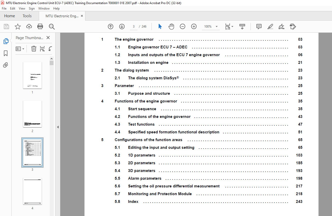
TABLE OF CONTENTS:
MTU Electronics Training Documentation for Electronic Engine Control Unit ECU-7 (ADEC) Technical Documentation Manual T000001-01E PDF DOWNLOAD
Title.......................................................................  1
Table of Contents...........................................................  3
1 The engine governor.......................................................  5
	1.1 Engine governor ECU 7 – ADEC........................................  5
		General information.................................................  5
		Application.........................................................  5
		Engine types........................................................  6
		Series..............................................................  6
		Main features.......................................................  6
		Adaptation of the engine governor...................................  6
	1.2 Inputs and outputs of the ECU 7 engine governor.....................  8
		Block diagram.......................................................  8
		Number of inputs and outputs........................................ 10
		Connector Assignment................................................ 11
		Pin assignment X1................................................... 11
		Pin assignment X2................................................... 14
		Pin assignment X3................................................... 18
		Pin assignment X4................................................... 20
	1.3 Installation on engine.............................................. 23
		Specifications...................................................... 23
		Mechanical installation............................................. 23
2 The dialog system......................................................... 25
	2.1 The dialog system DiaSys ®.......................................... 25
		General information................................................. 25
		Design.............................................................. 25
		Connection options.................................................. 25
		Software............................................................ 26
3 Parameter................................................................. 27
	3.1 Purpose and structure............................................... 27
		What is a parameter?................................................ 27
		Dongle and access options........................................... 27
		Structure of a ..................................................... 28
		Number ranges....................................................... 28
4 Functions of the engine governor.......................................... 37
	4.1 Start sequence...................................................... 37
		Engine governor-internal starting sequence.......................... 37
		General information................................................. 37
		Settings............................................................ 37
		Functions of the starting sequence.................................. 38
		Start request (initialization from S1).............................. 39
		Non-stored start.................................................... 39
		Stored start........................................................ 39
		Prelubrication...................................................... 39
		Stop request........................................................ 39
		Coolant temperature................................................. 39
		Prelubrication (S2, S3)............................................. 40
		Starting (S4)....................................................... 41
		Starter speed (S5, S6).............................................. 41
		Starter release speed (S7).......................................... 42
		Idle speed (S8)..................................................... 42
		Start termination (S9).............................................. 42
		Manual turning...................................................... 42
		Setting parameters.................................................. 42
		Alarm parameters.................................................... 44
	4.2 Functions of the engine governor.................................... 45
		Idle-maximum-speed governor — variable-speed governor............... 45
		Common Rail injection system........................................ 45
		Angle measurement/determination of injection timing................. 46
		Crankshaft:......................................................... 46
		Camshaft:........................................................... 46
		Adjustable speed droop.............................................. 46
		Power limitations................................................... 47
		Exhaust turbocharger................................................ 47
		Cylinder cutout..................................................... 47
		Overspeed........................................................... 48
	4.3 Test functions...................................................... 49
		Bedia level sensors................................................. 49
		Binary outputs...................................................... 51
		Overspeed........................................................... 51
		Integrated test system – diagnosis lamp DILA........................ 52
	4.4 Specified speed formation functional description.................... 53
		General information................................................. 53
		Selection of the speed setpoint source.............................. 53
		Specified speed formation........................................... 54
		Speed setpoint source............................................... 54
		Selection of the input.............................................. 55
		Setting the inputs for analog specified speed at the governor ...... 55
		Selector switch..................................................... 56
		Up/Down button...................................................... 57
		Speed limits........................................................ 58
		Sensor defect....................................................... 59
		Default value mode.................................................. 59
		Idle speed increase................................................. 59
		Specified speed ramp................................................ 59
		Speed droop......................................................... 62
		Limitation of the effective speed setpoint.......................... 63
		Speed increase (Genset application)................................. 63
		Idle speed increase................................................. 64
		Specified speed limitation.......................................... 64
		Example............................................................. 64
5 Configurations of the function areas...................................... 67
	5.1 Editing the input and output setting................................ 67
		Function area in the Diasys......................................... 67
		General information................................................. 67
		Transistor outputs, engine.......................................... 68
		Transistor outputs, plant........................................... 70
		Settings............................................................ 70
		Example 1........................................................... 71
		Example 2........................................................... 71
		Example 3........................................................... 71
		Default values...................................................... 72
		Analog outputs...................................................... 73
		Settings............................................................ 73
		Example............................................................. 73
		Default values...................................................... 74
		Binary outputs...................................................... 74
		Channel assignment.................................................. 75
		Default values...................................................... 75
		ZKP numbers that can be used for the various inputs and outputs .... 76
	5.2 1D parameters.......................................................105
		Definition..........................................................105
		Function area in the Diasys.........................................105
		Sensor types........................................................109
		Reference ECU input channel - channel No............................110
		1D parameters.......................................................110
		Details on the parameters...........................................183
		ZKP No. 1.2500.001..................................................183
		ZKP No. 2.0500.001..................................................183
		ZKP No. 2.0500.004..................................................184
		ZKP No. 2.0500.008..................................................184
		ZKP No. 2.1000.007..................................................184
		ZKP No. 2.1010.009..................................................186
		ZKP No. 2.1050.009..................................................186
	5.3 2D parameters.......................................................187
		Definition..........................................................187
		Function area in the Diasys.........................................187
		Curves (2D parameters)..............................................189
	5.4 3D parameters.......................................................195
		Definition..........................................................195
		Function area in the Diasys.........................................195
	5.5 Alarm parameters....................................................200
		Function area in the Diasys.........................................200
		Setting options for each alarm measurement point....................201
		Standard settings...................................................202
		Marine application..................................................202
		Rail application....................................................202
		Genset application..................................................202
		Application C&I.....................................................210
		Conversion of exported values.......................................217
		Values of the individual bits.......................................217
		Example.............................................................218
	5.6 Setting the oil pressure differential measurement...................219
		Principle...........................................................219
		Parameter...........................................................219
	5.7 Monitoring and Protection Module....................................220
		Function area in the Diasys ®.......................................220
		General information.................................................224
		Structure of the function element ..................................225
		Difference formation................................................226
		Limit value formation...............................................226
		Interface for the function element .................................227
		Structure of the function element ..................................227
		Behavior of the Protection module...................................227
		Characteristics of the Protection module............................228
		Calculation of the ZKP No. for parameters...........................229
		Values for calculation..............................................229
		Example.............................................................230
		Setting the various functions.......................................230
		Relevant settings...................................................230
		Warning function....................................................232
		Parameter setting for a warning (the behavior of the Protection ....232
		Use ................................................................233
		Limitation function using the example of engine coolant temperat....234
		Parameter setting for a limitation (the behavior of the Protecti....235
		Use ................................................................236
		Reduction function..................................................237
		Parameter setting for a reduction (the behavior of the Protectio....238
		Use ................................................................239
		Stop function.......................................................240
		Parameter setting for tripping a stop (the behavior of the Prote....241
		Use ................................................................242
		Limitation with delayed alarm.......................................243
	5.8 Index...............................................................245
More products