$40
MTU Engine Control Unit ECU 4S DDC MTU series 2000 Manual Operation Manual E531691-01E PDF
MTU Engine Control Unit ECU 4S DDC MTU series 2000 Manual Operation Manual E531691-01E PDF DOWNLOAD
FILE DETAILS:
MTU Engine Control Unit ECU 4S DDC MTU series 2000 Manual Operation Manual E531691-01E PDF DOWNLOAD
Language : English
Pages : 174
Downloadable : Yes
File Type : PDF
IMAGES PREVIEW OF THE MANUAL:
DESCRIPTION:
MTU Engine Control Unit ECU 4S DDC MTU series 2000 Manual Operation Manual E531691-01E PDF DOWNLOAD
General Information about Documentation
Documentation Structure
| Documentation Part | Title/Contents | Target Group(s) |
|---|---|---|
| 1 | Structure and function | Operating personnel, etc. |
| 2 | Operation | Operating personnel |
| 3 | Maintenance and repair | Plant personnel |
| 4 | Service manual | Electronic service personnel |
| 5 | Illustrated parts catalog | Operating personnel, electronic service personnel, logistics personnel |
| 6 | Plant-specific configuration | Electronic service personnel, installation personnel, start-up personnel |
| 7 | Mechanical and electrical installation | Installation personnel (electromechanical/mechatronic engineer) |
| 8 | Initial start-up | Start-up personnel |
Note: Not all parts of the documentation are written for every product.
Required Knowledge
To understand each part of the documentation, we recommend reading the preceding parts, if applicable.
Reference Numbers and Reference LinesDetails in figures are provided with reference numbers and reference lines if necessary.If reference is made in the text to a detail provided with a reference number, the figure number and, separated by an oblique, the reference number of the detail are written in brackets. Example: (5/2) means fig. 5, reference number 2.A point at the end of the reference line means that the detail is visible in the figure.
An arrow at the end of the reference line indicates that the detail cannot be seen in the figure.
SymbolsThe symbols used in safety notes are defined in the chapter “Safety requirements”.
TABLE OF CONTENTS:
MTU Engine Control Unit ECU 4S DDC MTU series 2000 Manual Operation Manual E531691-01E PDF DOWNLOAD
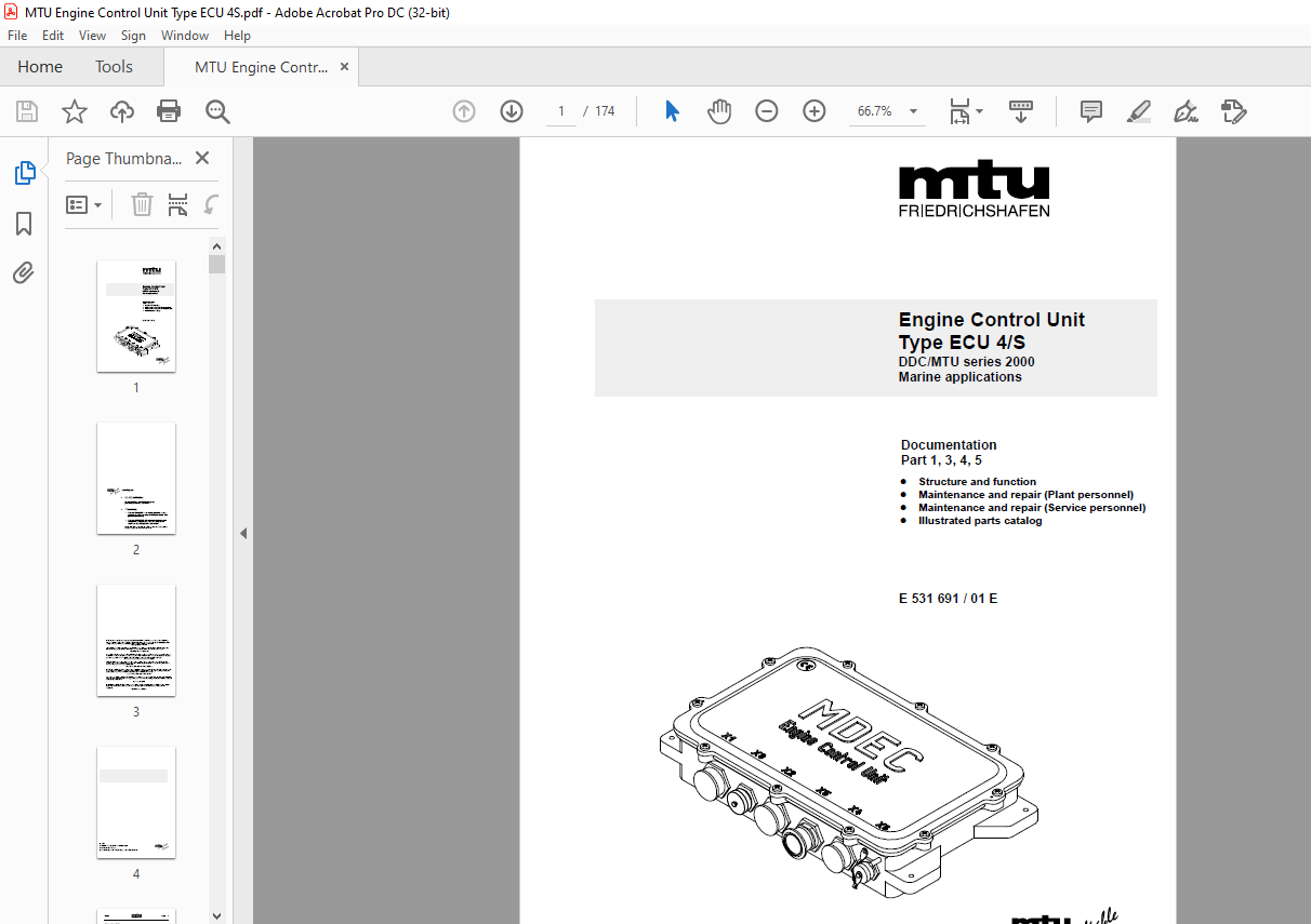
E 531 691 / 01 E
Engine Control Unit
Type ECU 4/S
DDC/MTU series 2000
Marine applications
Documentation Part 1, 3, 4, 5
– Structure and function
– Maintenance and repair (Plant personnel)
– Maintenance and repair (Service personnel)
– Illustrated parts catalog
HOME................................................................................................  0
Title...............................................................................................  1
Guide...............................................................................................  5
	Table of contents...............................................................................  5
	Abbreviations................................................................................... 10
	General information about documentation......................................................... 13
1 Structure and function............................................................................ 16
	1.1 Use and structure........................................................................... 16
		1.1.1 Use................................................................................... 16
		1.1.2 Structure of Engine Control Unit ECU 4/S.............................................. 18
			1.1.2.1 External structure.............................................................. 18
			1.1.2.2 Internal structure.............................................................. 20
			1.1.2.3 Attachment of Engine Control Unit ECU 4/S to the engine......................... 22
	1.2 Functions of electronic Engine Control Unit ECU 4/S......................................... 23
		1.2.1 Engine governing/control.............................................................. 23
		1.2.2 Software.............................................................................. 24
		1.2.3 Speed/injection governing............................................................. 25
		1.2.4 PLD injection system.................................................................. 26
		1.2.5 Angle measurement/determining control timing.......................................... 27
		1.2.6 Adjustable speed droop................................................................ 28
		1.2.7 Power limitation (quantity limitation)................................................ 29
			1.2.7.1 Dynamic quantity limitation..................................................... 29
			1.2.7.2 Fixed quantity limitation....................................................... 29
			1.2.7.3 Start feeding control........................................................... 29
			1.2.7.4 Speed limitation................................................................ 29
		1.2.8 Nominal speed value handling.......................................................... 30
		1.2.9 Recirculating ETC control............................................................. 31
		1.2.10 Cylinder cutout...................................................................... 32
	1.3 Start and stop functions.................................................................... 32
		1.3.1 Engine start.......................................................................... 32
		1.3.2 Emergency engine start................................................................ 33
		1.3.3 Engine stop........................................................................... 33
		1.3.4 Emergency engine stop................................................................. 34
		1.3.5 Safety system override................................................................ 34
	1.4 Engine monitoring........................................................................... 35
		1.4.1 Safety system Sisy.................................................................... 35
		1.4.2 Integral Test System (ITS)............................................................ 36
			1.4.2.1 Monitoring the electronics of ECU 4/S........................................... 37
			1.4.2.2 Monitoring the sensors/actuators................................................ 37
			1.4.2.3 Monitoring bus communication.................................................... 37
	1.5 Status and fault displays................................................................... 38
	1.6 Communication and system integration via CAN bus............................................ 39
	1.7 Inputs/outputs of Engine Control Unit ECU 4/S............................................... 39
		1.7.1 Inputs on the plant side.............................................................. 39
			1.7.1.1 Assignment of inputs on the plant side.......................................... 39
			1.7.1.2 Input specifications............................................................ 40
		1.7.2 Inputs on the engine side............................................................. 42
			1.7.2.1 Assignment of inputs on the engine side......................................... 42
			1.7.2.2 Input specifications............................................................ 43
		1.7.3 Outputs on the plant side............................................................. 48
			1.7.3.1 Assignment of outputs on the plant side......................................... 48
			1.7.3.2 Output specifications........................................................... 49
		1.7.4 Outputs on the engine side............................................................ 51
			1.7.4.1 Assignment of outputs on the engine side........................................ 51
			1.7.4.2 Output specifications........................................................... 52
		1.7.5 Bus connections....................................................................... 54
			1.7.5.1 Serial interface RS232.......................................................... 54
			1.7.5.2 CAN bus interface............................................................... 55
	1.8 Technical data.............................................................................. 56
2 Operation......................................................................................... 59
3 Maintenance and repair (Plant personnel).......................................................... 63
	3.1 Safety requirements......................................................................... 63
	3.2 Maintenance................................................................................. 65
		3.2.1 General notes......................................................................... 65
		3.2.2 Maintenance work...................................................................... 68
			3.2.2.1 Maintenance intervals........................................................... 68
			3.2.2.2 Task summary for scheduled maintenance work..................................... 68
		3.2.3 Task overview -- visual inspection.................................................... 69
			3.2.3.1 Checking firm seating of all connectors......................................... 70
			3.2.3.2 Checking firm seating of cables................................................. 71
			3.2.3.3 Checking screwed sensor connections for leaks................................... 72
			3.2.3.4 Checking cables................................................................. 73
		3.2.4 Task overview -- cleaning............................................................. 74
			3.2.4.1 Cleaning Engine Control Unit ECU 4/S............................................ 75
			3.2.4.2 Cleaning connectors............................................................. 76
	3.3 Troubleshooting............................................................................. 77
		3.3.1 Faults without fault code display..................................................... 77
		3.3.2 Faults with fault code display........................................................ 80
		3.3.3 Faults indicated by LEDs..............................................................105
	3.4 Repair......................................................................................106
		3.4.1 Replacing Engine Control Unit ECU 4/S.................................................106
			3.4.1.1 Removing the housing of Engine Control Unit ECU 4/S from the engine.............108
			3.4.1.2 Removing the cover of Engine Control Unit ECU 4/S...............................109
			3.4.1.3 Transferring the memory modules of Engine Control Unit ECU 4/S..................110
			3.4.1.4 Fitting the cover of Engine Control Unit ECU 4/S................................112
			3.4.1.5 Mounting the housing of Engine Control Unit ECU 4/S on the engine...............113
		3.4.2 Replacing the fusible cutout in ECU 4/S...............................................115
			3.4.2.1 Removing the cover of Engine Control Unit ECU 4/S when mounted on the engine....116
			3.4.2.2 Replacing the fusible cutout....................................................117
			3.4.2.3 Fitting the cover of Engine Control Unit ECU 4/S when mounted on the engine.....118
4 Maintenance and repair (Service personnel)........................................................121
	4.1 Safety requirements.........................................................................121
	4.2 Maintenance.................................................................................123
		4.2.1 General notes.........................................................................123
		4.2.2 Maintenance work......................................................................123
	4.3 Troubleshooting.............................................................................123
		4.3.1 Faults with fault code display........................................................123
	4.4 Repair......................................................................................129
		4.4.1 Replacing data module IDM.............................................................131
			4.4.1.1 Removing the cover of Engine Control Unit ECU 4.................................132
			4.4.1.2 Replacing Interface Data Module IDM.............................................133
			4.4.1.3 Fitting the cover of Engine Control Unit ECU 4 when mounted on the engine.......135
		4.4.2 Replacing data module EDM.............................................................136
			4.4.2.1 Removing the cover of Engine Control Unit ECU 4.................................137
			4.4.2.2 Replacing Engine Data Module EDM................................................137
			4.4.2.3 Fitting the cover of Engine Control Unit ECU 4..................................139
	4.5 Metrological tests..........................................................................139
		4.5.1 Testing the CAN bus...................................................................139
			4.5.1.1 CAN bus short-circuit test......................................................140
			4.5.1.2 Checking and repairing shielding................................................142
5 Illustrated parts catalog.........................................................................144
	5.1 Introduction................................................................................144
	5.2 Drawings and tables.........................................................................147
		527 530 37 60...............................................................................148
	5.3 Cross-reference list........................................................................151
Appendix............................................................................................153
	A: Connector pin assignment.....................................................................155
	B: Input circuitry of the ECU channels..........................................................169
More products