$40
MTU Propulsion plant Remote Control System RCS-5 FPP 01-03 B Operation Manual E531942-01E PDF
MTU Propulsion plant Remote Control System RCS-5 FPP 01-03 B Operation Manual E531942-01E PDF DOWNLOAD
FILE DETAILS:
MTU Propulsion plant Remote Control System RCS-5 FPP 01-03 B Operation Manual E531942-01E PDF DOWNLOAD
Language : English
Pages : 166
Downloadable : Yes
File Type : PDF
IMAGES PREVIEW OF THE MANUAL:

DESCRIPTION:
MTU Propulsion plant Remote Control System RCS-5 FPP 01-03 B Operation Manual E531942-01E PDF DOWNLOAD
General Information about Documentation
Documentation Structure
| Documentation Part | Title/Contents | Target Group(s) |
|---|---|---|
| 1 | Structure and function | Operating personnel, etc. |
| 2 | Operation | Operating personnel |
| 3 | Maintenance and repair | Plant personnel |
| 4 | Service manual | Electronic service personnel |
| 5 | Illustrated parts catalog | Operating personnel, electronic service personnel, logistics personnel |
| 6 | Plant-specific configuration | Electronic service personnel, installation personnel, start-up personnel |
| 7 | Mechanical and electrical installation | Installation personnel (electromechanical/mechatronic engineer) |
| 8 | Initial start-up | Start-up personnel |
Note: Not all parts of the documentation are written for every product.
Required KnowledgeTo understand each part of the documentation, we recommend reading the preceding parts, if applicable.
Reference Numbers and Reference LinesDetails in figures are provided with reference numbers and reference lines if necessary.If reference is made in the text to a detail provided with a reference number, the figure number and, separated by an oblique, the reference number of the detail are written in brackets. Example: (5/2) means fig. 5, reference number 2.A point at the end of the reference line means that the detail is visible in the figure.An arrow at the end of the reference line indicates that the detail cannot be seen in the figure.
SymbolsThe symbols used in safety notes are defined in the chapter “Safety requirements”.
TABLE OF CONTENTS:
MTU Propulsion plant Remote Control System RCS-5 FPP 01-03 B Operation Manual E531942-01E PDF DOWNLOAD
Propulsion plant
Remote Control System
RCS-5 FPP 01-03/B
E 531 942 / 01 E
Documentation Parts 1, 2
Title........................................................................................................................................  1
Guide........................................................................................................................................  3
	Table of contents........................................................................................................................  3
	Abbreviations............................................................................................................................  8
	General information about documentation.................................................................................................. 12
Part 1 Structure and function................................................................................................................ 15
	1 Structure and function................................................................................................................. 17
		1.1 Overview......................................................................................................................... 17
			1.1.1 Use of RCS-5 FPP 01-03/B................................................................................................... 17
			1.1.2 Features of RCS-5 FPP 01-03/B.............................................................................................. 17
			1.1.3 Integration of RCS-5 FPP 01-03/B in the overall system..................................................................... 19
				1.1.3.1 Exemplary application................................................................................................ 19
				1.1.3.2 Functional levels.................................................................................................... 20
				1.1.3.3 Bus communication.................................................................................................... 20
				1.1.3.4 Process interfacing.................................................................................................. 21
				1.1.3.5 Interfaces to other MTU systems and devices.......................................................................... 21
				1.1.3.6 Interfaces to systems produced by other manufacturers................................................................ 21
		1.2 Structure of RCS-5 FPP 01-03/B................................................................................................... 22
			1.2.1 Overview................................................................................................................... 22
			1.2.2 Integration of the individual assemblies in the overall system............................................................. 23
			1.2.3 Identification of hardware and software.................................................................................... 23
			1.2.4 Control lever panel........................................................................................................ 24
				1.2.4.1 Connection and structure of the control lever panel.................................................................. 24
				1.2.4.2 LC propulsion stage scale............................................................................................ 28
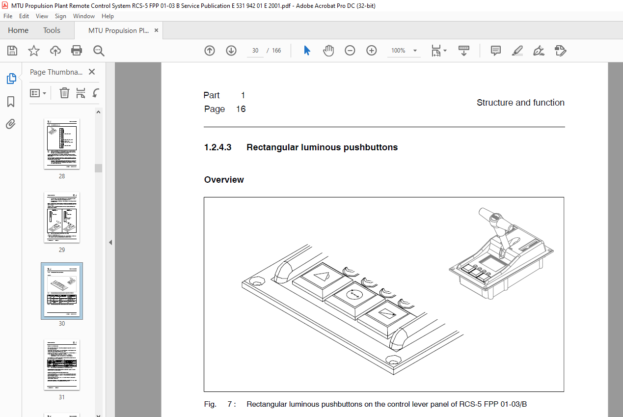
				1.2.4.3 Rectangular luminous pushbuttons..................................................................................... 30
				1.2.4.4 LC graphic display and the associated function keys.................................................................. 32
				1.2.4.5 Interfaces and cable connections of the control lever panel.......................................................... 49
			1.2.5 Option: Trolling Control Unit TCU.......................................................................................... 50
				1.2.5.1 Terminal box......................................................................................................... 50
				1.2.5.2 Trolling PIM......................................................................................................... 50
			1.2.6 Option: Additional PAN control panels...................................................................................... 50
		1.3 Operating functions of RCS-5 FPP 01-03/B......................................................................................... 51
			1.3.1 Assuming command after switching on........................................................................................ 51
			1.3.2 Command transfer........................................................................................................... 51
				1.3.2.1 Initiation........................................................................................................... 51
				1.3.2.2 Control station priorities........................................................................................... 52
				1.3.2.3 Control lever requirement, slave display, transitional phase and timeout............................................. 54
				1.3.2.4 Assuming command when the target control station has priority 1 or 2................................................. 56
				1.3.2.5 Requesting command when the target control station has priority 3.................................................... 57
				1.3.2.6 Relinquishing command (regardless of control station priority)....................................................... 58
				1.3.2.7 Special cases for command transfer................................................................................... 58
				1.3.2.8 Option: “Parallel command transfer”.................................................................................. 59
			1.3.3 Acquisition and processing of the control lever handle setting............................................................. 60
				1.3.3.1 Propulsion stage acquisition......................................................................................... 60
				1.3.3.2 Propulsion curves and engagement/disengagement ranges................................................................ 60
				1.3.3.3 Engine speed control................................................................................................. 62
				1.3.3.4 Gear control......................................................................................................... 62
			1.3.4 Single control lever mode (SCL mode)....................................................................................... 64
			1.3.5 Warm-up function........................................................................................................... 68
			1.3.6 Option: Trolling mode...................................................................................................... 69
			1.3.7 Option: Additional operating modes......................................................................................... 70
			1.3.8 Changing between Remote control and Local mode............................................................................. 71
			1.3.9 Responses of RCS-5 FPP 01-03/B to emergency engine stop.................................................................... 72
			1.3.10 Testing and monitoring features........................................................................................... 73
				1.3.10.1 Lamp test........................................................................................................... 73
				1.3.10.2 Integral Test System................................................................................................ 73
				1.3.10.3 Fault categories and fault codes.................................................................................... 75
			1.3.11 Signalling and alarms..................................................................................................... 76
				1.3.11.1 Types, sources and media............................................................................................ 76
				1.3.11.2 Neutral signalling.................................................................................................. 76
				1.3.11.3 Operator prompts.................................................................................................... 77
				1.3.11.4 Automatic alarm sequences........................................................................................... 78
				1.3.11.5 Alarm acknowledgement............................................................................................... 79
		1.4 Customization and dialog features................................................................................................ 80
			1.4.1 Customization of system components......................................................................................... 80
			1.4.2 Software and data.......................................................................................................... 80
			1.4.3 Dialog function and dialog parameters...................................................................................... 81
		1.5 Redundancy....................................................................................................................... 82
			1.5.1 Shaft-related field bus (propulsion arrangement field bus)................................................................. 82
			1.5.2 Control lever panels....................................................................................................... 82
			1.5.3 Control lever panel on the main control station............................................................................ 83
			1.5.4 Data management............................................................................................................ 83
		1.6 Technical data of the control lever panel........................................................................................ 86
Part 2 Operation............................................................................................................................. 89
	2 Operation.............................................................................................................................. 91
		2.1 Safety requirements.............................................................................................................. 91
		2.2 About the operating tables....................................................................................................... 93
			2.2.1 Structure and reading order................................................................................................ 93
			2.2.2 Phraseology, terms and key designations.................................................................................... 93
		2.3 Overview of operating procedures................................................................................................. 94
		2.4 Switching the Remote Control System on........................................................................................... 95
		2.5 Assuming initial command at a control lever panel................................................................................ 98
		2.6 Command transfer without the “parallel command transfer” option.................................................................. 99
			2.6.1 Initiation by the inactive control station................................................................................. 99
				2.6.1.1 Assuming command on a priority 1 or 2 target control station......................................................... 99
				2.6.1.2 Requesting command on a priority 3 target control station............................................................104
			2.6.2 Initiation by the active control station...................................................................................109
		2.7 Command transfer with the “Parallel command transfer” option.....................................................................114
			2.7.1 Initiation by the inactive control station.................................................................................114
			2.7.1.1 Assuming command on a priority 1 or 2 target control station.............................................................114
		2.8 Engaging/disengaging and changing speed (without special operating modes, e.g. Trolling mode)....................................119
			2.8.1 Engaging ahead.............................................................................................................119
			2.8.2 Increasing forward thrust with the gear engaged ahead......................................................................120
			2.8.3 Decreasing forward thrust with the gear engaged ahead......................................................................121
			2.8.4 Disengaging with the gear engaged ahead....................................................................................122
			2.8.5 Engaging astern............................................................................................................123
			2.8.6 Increasing reverse thrust with the gear engaged astern.....................................................................124
			2.8.7 Decreasing reverse thrust with the gear engaged astern.....................................................................125
			2.8.8 Disengaging with the gear engaged astern...................................................................................126
		2.9 Single control lever mode (SCL mode).............................................................................................127
			2.9.1 Selecting single control lever mode........................................................................................127
			2.9.2 Deselecting single control lever mode for an SCL passive propulsion shaft..................................................130
			2.9.3 Deselecting single control lever mode for all propulsion shafts............................................................131
		2.10 Using the warm-up function......................................................................................................133
		2.11 Optional operating modes........................................................................................................135
			2.11.1 Selecting an operating mode...............................................................................................135
			2.11.2 Deselecting an operating mode.............................................................................................136
			2.11.3 Example: Selecting Trolling mode..........................................................................................137
			2.11.4 Example: Deselecting trolling mode........................................................................................138
		2.12 Changing between Remote control and Local mode..................................................................................140
			2.12.1 Selecting Local mode during multi control lever mode......................................................................140
			2.12.2 Selecting Local mode on an SCL passive shaft in SCL mode..................................................................141
			2.12.3 Selecting Local mode on an SCL active shaft in SCL mode...................................................................142
			2.12.4 Deselecting Local mode....................................................................................................144
		2.13 Performing a lamp test..........................................................................................................146
		2.14 Switching text language on the LC graphic display...............................................................................147
		2.15 Adjusting brightness and contrast...............................................................................................148
		2.16 Responding to faults............................................................................................................150
			2.16.1 First step: Defining the fault............................................................................................150
			2.16.2 General: Checking alarm entries on the LC graphic display.................................................................150
			2.16.3 Responses to combined alarms during multi control lever mode..............................................................150
				2.16.3.1 Category 1 combined alarm...........................................................................................151
				2.16.3.2 Category 2 combined alarm caused by failure of the control lever panel on a non-commanding slave control station....152
				2.16.3.3 Category 2 combined alarm caused by failure of the control lever panel on the commanding slave control station......153
				2.16.3.4 Category 3 combined alarm caused by failure of the control lever panel on the main control station..................156
				2.16.3.5 Category 3 combined alarm caused by failure of another element vital to remote control..............................157
			2.16.4 Special partial failure of control lever panels of one propulsion shaft...................................................158
				2.16.4.1 Failure of electronic circuit A in the control lever panel of the main control station..............................158
				2.16.4.2 Failure of electronic circuit A in the commanding control lever panel...............................................159
				2.16.4.3 Failure of electronic circuit B in the commanding control lever panel...............................................160
		2.17 Switching the Remote Control System off.........................................................................................161
Appendix.....................................................................................................................................163
	A Control station priority settings......................................................................................................165

