$33
Mustang All Wheel Loader ML360 ML460 Service Manual (918294) – PDF DOWNLOAD
Mustang All Wheel Loader ML360 ML460 Service Manual (918294) – PDF DOWNLOAD
DESCRIPTION:
Mustang All Wheel Loader ML360 ML460 Service Manual (918294) – PDF DOWNLOAD
Operation
1.1 Important information about this manual
- Your decision to purchase Mustang equipment was a good one. We are sure that your decision was carefully considered and that you are looking forward to many years of reliable performance from this machine. Mustang Manufacturing has invested much time and effort in developing its lines of equipment.
- The equipment you have purchased is built with a great deal of pride, and designed to provide long life, efficient operation, durability, and dependability. Modern machinery has become more sophisticated and, with that in mind, Mustang Manufacturing asks that you read and COMPLETELY understand the contents of this manual and become familiar with your new machine, BEFORE attempting to service it.
- This manual was developed specifically for the machine you have purchased. The information within is for your assistance in preparing, adjusting, maintaining, and servicing your machine. More importantly, this manual provides a service plan for safe and proper use of your machine. Refer to the Table of Contents for an outline (by chapters) of this manual. Use the Index, located at the back of this manual, for specific chapter and topic/page number references.
- If this machine is re-sold, Mustang Manufacturing recommends that this manual be given to the new owner. If this machine was purchased “used,” or if the owner’s address has changed, please provide your Mustang dealer or Mustang Manufacturing Company with the owner’s name and current address, along with the machine model and serial number.
- This will allow the registered owner’s information to be updated, so that the owner can be notified directly in case of an important product issue, such as a safety update program. “Right” and “left” are determined from the position of sitting in the operator’s seat, facing forward.
- Mustang Manufacturing reserves the right to make changes or improvements in the design or construction of any part without incurring the obligation to install such changes on any unit previously delivered. Throughout this manual, information is provided that is introduced by the word “NOTE” or “IMPORTANT.” Be sure to read carefully and comply with the message or directive given.
- Following this information will improve your maintenance efficiency, help you to avoid costly breakdowns or unnecessary damage, and extend your machine’s life. Operational safety and readiness of the machine depend partially on maintenance and service of the machine.
- This is why regular maintenance and service work is absolutely necessary. Extensive maintenance and repair work must always be carried out by a qualified technician with appropriate training. Insist on using Mustang original service parts when carrying out maintenance and repair work.
- This ensures operational safety and readiness of your machine, and maintains its value. Our wide dealership network stands ready to provide any assistance required, including genuine Mustang service parts. All parts should be obtained from or ordered through your Mustang dealer.
- Give complete information about the part as well as the model number and serial number of your machine. Record numbers, in the spaces provided, as a handy record for quick reference.
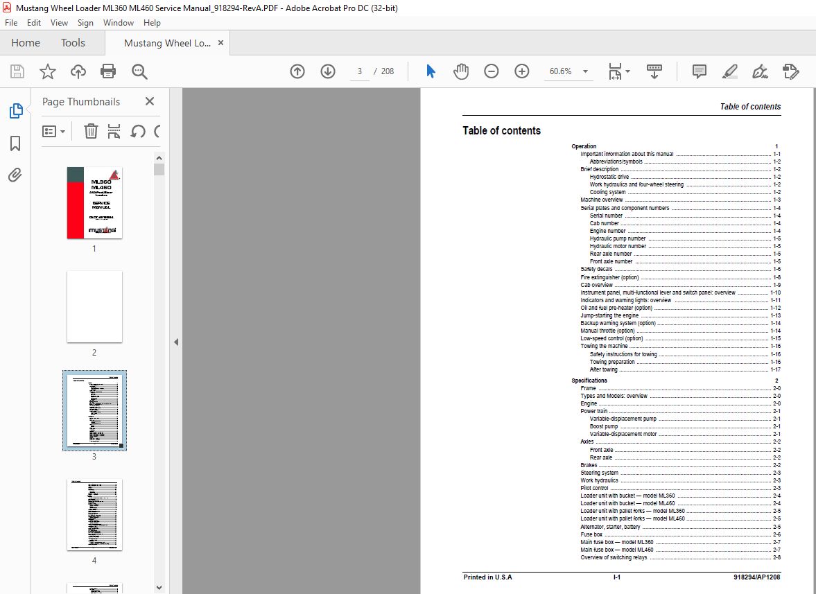
TABLE OF CONTENTS:
Mustang All Wheel Loader ML360 ML460 Service Manual (918294) – PDF DOWNLOAD
Operation 1
Important information about this manual 1-1
Abbreviations/symbols 1-2
Brief description 1-2
Hydrostatic drive 1-2
Work hydraulics and four-wheel steering 1-2
Cooling system 1-2
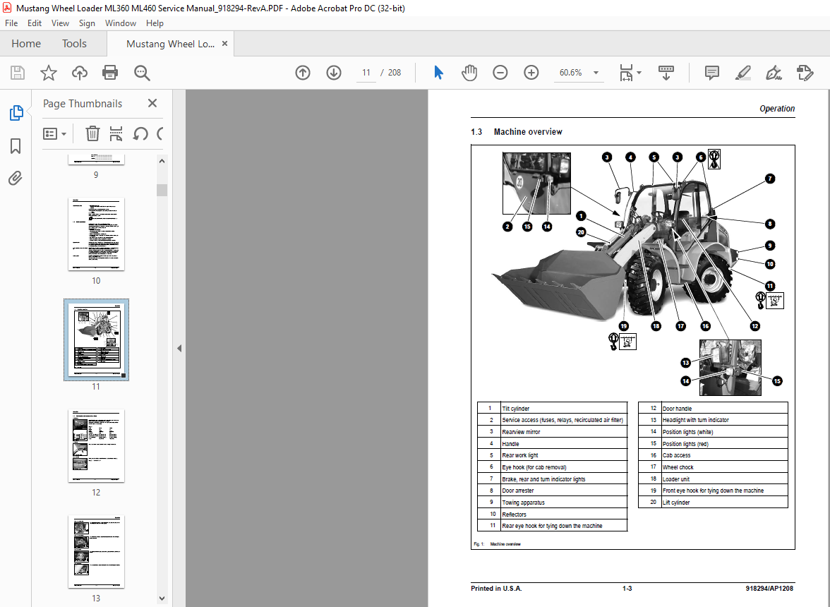
Machine overview 1-3
Serial plates and component numbers 1-4
Serial number 1-4
Cab number 1-4
Engine number 1-4
Hydraulic pump number 1-5
Hydraulic motor number 1-5
Rear axle number 1-5
Front axle number 1-5
Safety decals 1-6
Fire extinguisher (option) 1-8
Cab overview 1-9
Instrument panel, multi-functional lever and switch panel: overview 1-10
Indicators and warning lights: overview 1-11
Oil and fuel pre-heater (option) 1-12
Jump-starting the engine 1-13
Backup warning system (option) 1-14
Manual throttle (option) 1-14
Low-speed control (option) 1-15
Towing the machine 1-16
Safety instructions for towing 1-16
Towing preparation 1-16
After towing 1-17
Specifications 2
Frame 2-0
Types and Models: overview 2-0
Engine 2-0
Power train 2-1
Variable-displacement pump 2-1
Boost pump 2-1
Variable-displacement motor 2-1
Axles 2-2
Front axle 2-2
Rear axle 2-2
Brakes 2-2
Steering system 2-3
Work hydraulics 2-3
Pilot control 2-3
Loader unit with bucket — model ML360 2-4
Loader unit with bucket — model ML460 2-4
Loader unit with pallet forks — model ML360 2-5
Loader unit with pallet forks — model ML460 2-5
Alternator, starter, battery 2-5
Fuse box 2-6
Main fuse box — model ML360 2-7
Main fuse box — model ML460 2-7
Overview of switching relays 2-8
Table of contents
Table of contents
918294/AP1208 I-2 Printed in USA
Tires for wheel loader — model ML360 2-9
Tires for wheel loader — model ML460 2-9
Weights 2-9
Noise levels 2-9
Vibration 2-10
Hardware torques 2-10
General torques 2-10
Specific torques 2-10
Dimensions — model ML360 2-11
Dimensions — model ML460 2-12
Maintenance 3
Introduction 3-0
Important information on maintenance and service work 3-0
Fluids and lubricants 3-1
Index to component maintenance 3-2
Explanation of symbols on maintenance label 3-3
Maintenance label 3-4
Maintenance schedule 3-5
Maintenance of the fuel system 3-8
Specific safety instructions 3-8
Refueling 3-8
Stationary fuel pumps 3-8
Diesel fuel specification 3-8
Replacing the fuel filter 3-9
Cleaning the fuel pump screen filter 3-10
Bleeding the fuel system 3-10
Checking/adding engine oil 3-11
Changing engine oil 3-12
Changing the engine oil filter cartridge 3-13
Engine and hydraulics cooling system 3-14
Specific safety instructions 3-14
Cleaning the oil cooler 3-14
Hydraulic system 3-15
Specific safety instructions 3-15
Checking hydraulic pressure lines 3-16
Specific safety instructions 3-16
Monitoring the hydraulic oil return filter 3-17
Important information for the use of biodegradable oil 3-17
Hydraulic oil return filter 3-18
Changing the filter insert 3-18
Checking the hydraulic oil level 3-19
Adding hydraulic oil 3-19
Changing the hydraulic oil 3-20
Rear axle transfer gearbox oil levels 3-21
Front and rear axle differential oil levels 3-22
Front and rear axle planetary drive oil levels 3-23
Air filter maintenance 3-24
Check: air filter contamination 3-24
Replacing the air filter cartridge 3-25
V-belt 3-26
Checking V-belt tension 3-26
Tensioning the V-belt 3-26
Lubrication points 3-27
Lubricating the rear axle oscillation-type bearing 3-27
Lubricating the front and rear axle planetary drive bearings 3-27
Lubricating the loader unit 3-28
Table of contents
Printed in USA I-3 918294/AP1208
Attachment maintenance 3-28
Brake system 3-29
Specific safety instructions 3-29
Checking/adding brake fluid 3-29
Repair work on the brake system 3-29
Tire care 3-30
Daily tire check 3-30
Weekly check 3-30
Changing wheels 3-31
Heating 3-32
Cleaning the dust filter of the heating system 3-32
Electric system 3-33
Safety instructions 3-33
Service and maintenance work at regular intervals 3-34
Cables, bulbs and fuses 3-34
Alternator 3-34
Battery maintenance 3-35
General maintenance work 3-36
Cleaning 3-36
When using washing solvents 3-36
When using compressed air 3-36
When using a high-pressure or steam jet cleaner 3-36
When using volatile and flammable anti-corrosion agents and sprays 3-36
Cleaning inside the cab 3-37
Cleaning the seat belt 3-37
Machine exterior 3-37
Engine compartment 3-38
Bolted connections, hinges 3-38
Engine 4
F4M 2011/BF4M 2011 engine: overview 4-0
Engine oil cooling 4-1
Fuel system 4-2
Checking and adjusting valve clearance 4-3
Replacing the fuel injection pump 4-4
Setting the charge-air pressure — model ML460 4-9
Charge-pressure dependent full-load stop — model ML460 4-10
Turning off minus compensation 4-10
Minus compensation — function 4-10
Switching off minus compensation — model ML360 4-11
Heating connection 4-11
Removing/mounting the cylinder head 4-12
Sealing the bleeder valve 4-16
Intake/exhaust manifold 4-16
Engine trouble 4-17
Power train 5
Variable-displacement pump test ports — model ML360 5-0
Variable-displacement pump — model ML360 5-1
Variable-displacement pump test ports, 12 mph (20 kph) — model ML460 5-2
Variable-displacement pump, 12 mph (20 kph) — model ML460 5-3
Variable-displacement motor, 12 mph (20 kph) — all models 5-4
5-4
Variable-displacement pump test po 5-4
Inching valve overview 5-5
Inching valve circuit, 12 mph (20 kph) 5-6
Drive circuit, 12 mph (20 kph) — model ML360 5-7
Drive, 12 mph (20 kph): wiring diagram 5-8
Table of contents
918294/AP1208 I-4 Printed in USA
Towing and transporting the machine 5-9
Transporting 5-9
Towing 5-9
Test report — model ML360 5-10
Test report — model ML460 5-11
Power train adjustment 5-12
Tools required 5-12
Adjusting boost pressure 5-12
Adjusting starting speed 5-12
Setting high pressure/drive pressure 5-13
Setting the secondary valves for forward/reverse driving 5-14
Setting the pump hydraulic resistance (characteristic curve) 5-14
Setting engine droop 5-15
Setting control initiation on the hydraulic motor 5-15
Setting the wheel speed 5-16
Tools required 5-16
Axles 6
Axle overview 6-0
Sealing service (joint housing/axle carrier) 6-1
Bevel gear shaft seals 6-12
Differential cage/differential lock screw connections 6-13
Overview of differential lock and differential cage 6-14
Removing the differential cage with the differential lock 6-15
Removing the differential lock 6-16
Assembling the differential lock 6-17
Removing the gearbox 6-18
Input shaft version 1 sealing: overview 6-24
Assembling the gearbox 6-25
Brakes 7
Brake circuit 7-0
Brake diagram 7-1
Handbrake circuit 7-2
Inching valve circuit, 12 mph (20 kph) 7-3
Service brake 7-4
Brake caliper maintenance 7-4
Steering 8
Steering circuit for model ML360 8-0
Steering diagram for model ML360 8-1
Steering circuit for model ML460 8-2
Steering diagram for model ML460 8-3
Steering system adjustment 8-4
Function 8-4
Checking a steering cylinder 8-4
Checking the check block 8-4
Hydraulic ports on servostat 8-5
Pressure relief valve: adjustment 8-5
Steering cylinder: seals 8-6
Overview of steering cylinder adjustment 8-7
Necessary tools 8-7
How to adjust the steering cylinders 8-8
Checking the track setting 8-9
Correcting the track setting 8-9
Setting the steering limit 8-10
Checking steering synchronization 8-11
Checking the bypass 8-11
Bleeding the steering cylinders 8-12
Table of contents
Printed in USA I-5 918294/AP1208
Setting steering synchronization 8-13
Final check/test run 8-13
Hydraulic system 9
Test report for model ML360 9-0
Test report for model ML460 9-1
Work hydraulics oil supply 9-2
Control valve ports 9-3
Priority valve ports 9-3
Priority valve diagram 9-4
Load stabilizer ports 9-4
Load stabilizer circuit 9-5
Load stabilizer diagram 9-5
Lift cylinder: seals 9-6
Tilt cylinder: seals 9-7
Control cylinder (quick-hitch frame): seals 9-8
Work hydraulics diagram 9-10
Electrical system 10
Ohm’s Law 10-0
Measuring equipment and methods 10-0
Terminal description 10-2
Cable color coding 10-6
Other color codes 10-8
Relays 10-8
Use, mode of function 10-8
Terminal description on relay 10-8
Starter, battery, alternator 10-9
Fuse box 10-9
Main fuse box with relays for model ML360 10-10
Main fuse box with relays for model ML460 10-10
Switching relays 10-11
Description of blocking diodes 10-12
Blocking diodes V8, V9 10-12
Blocking diode V10 10-12
Blocking diode V11 10-12
Blocking diodes V16, V17 10-12
Blocking diodes V20, V21 10-12
Overview of switch assignment 10-13
Installing a rotating beacon 10-14
Installing the backup warning system 10-14
Installing two front work lights 10-15
Installing two front work lights and one rear work light 10-15
Electric diagram (sheet 1) for model ML360 10-17
Electric diagram (sheet 2) for model ML360 10-18
Legend: electric diagram for model ML460 10-19
Electric diagram (sheet 1) for model ML460 10-20
Electric diagram (sheet 2) for model ML460 10-21
IMAGES PREVIEW OF THE MANUAL:
More products