$33
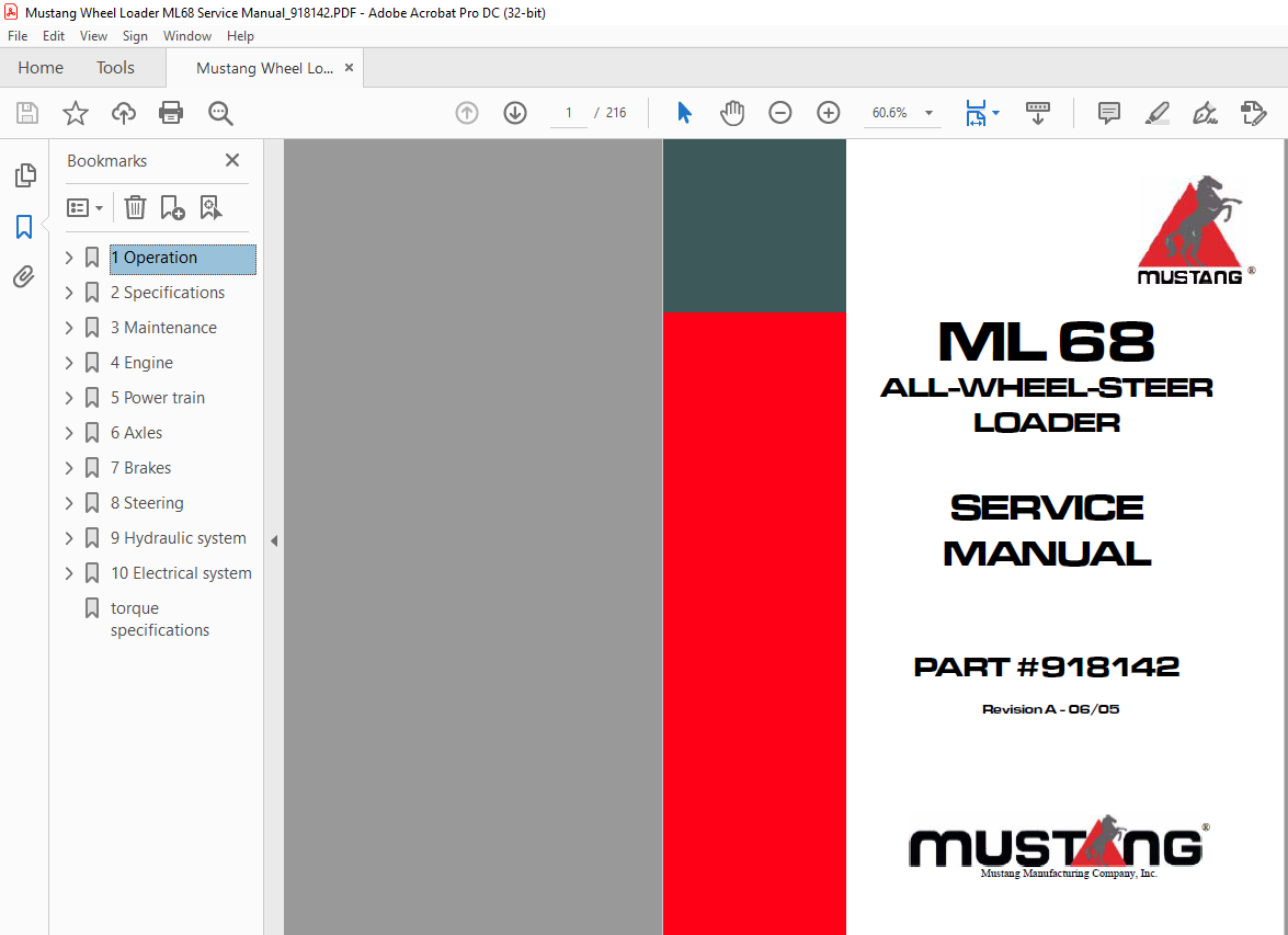
Mustang ALL-WHEEL-STEER LOADER ML 68 Service Manual(918142) – PDF DOWNLOAD
Mustang ALL-WHEEL-STEER LOADER ML 68 Service Manual(918142) – PDF DOWNLOAD
DESCRIPTION:
Mustang ALL-WHEEL-STEER LOADER ML 68 Service Manual(918142) – PDF DOWNLOAD
Operation
1. 1 Important information on this service manual
- Your decision to purchase this piece of Mustang equipment was a good one. We are sure that your decision was carefully considered and that you are looking forward to many years of reliable performance from this machine. Mustang Company has invested much time and effort in developing its lines of equipment.
- The equipment you have purchased is built with a great deal of pride, and designed to provide long life, efficient operation, durability and dependability. Modern machinery has become more sophisticated and, with that in mind, Mustang Company asks that you read and COMPLETELY understand the contents of this manual and become familiar with your new machine, BEFORE attempting to service it.
- This manual was developed specifically for the machine you have purchased. The information within is for your assistance in preparing, adjusting, maintaining and servicing your machine. More importantly, this manual provides a service plan for safe and proper use of your machine. Refer to the Table of Contents for an outline (by chapters) of this manual. Use the Index, located at the back of this manual, for specific chapter and topic/page number references. If this machine is resold, Mustang Company recommends that this manual be given to the new owner.
- If this machine was purchased “used,” or if the owner’s address has changed, please provide your Mustang dealer or Mustang Company with the owner’s name and current address, along with the machine model and serial number. This will allow the registered owner information to be updated, so that the owner can be notified directly in case of an important product issue, such as a safety update program.
- “Right” and “left” are determined from the position of sitting in the operator’s seat, facing forward. Mustang Company reserves the right to make changes or improvements in the design or construction of any part without incurring the obligation to install such changes on any unit previously delivered. Throughout this manual information is provided that is introduced by the word NOTE or IMPORTANT.
- Be sure to read carefully and comply with the message or directive given. Following this information will improve your maintenance efficiency, help you to avoid costly breakdowns or unnecessary damage and extend your machine’s life. Operational safety and readiness of the machine depend partially on maintenance and service of the machine. This is why regular maintenance and service work is absolutely necessary.
- Extensive maintenance and repair work must always be carried out by a qualified technician with appropriate training. Insist on using Mustang original service parts when carrying out maintenance and repair work. This ensures operational safety and readiness of your machine, and maintains its value.
- Our wide dealership network stands ready to provide any assistance required, including genuine Mustang service parts. All parts should be obtained from or ordered through your Mustang dealer. Give complete information about the part as well as the model number and serial number of your machine. Record numbers, in the spaces provided, as a handy record for quick reference.
TABLE OF CONTENTS:
Mustang ALL-WHEEL-STEER LOADER ML 68 Service Manual(918142) – PDF DOWNLOAD
Operation
Important information on this service manual 1-1
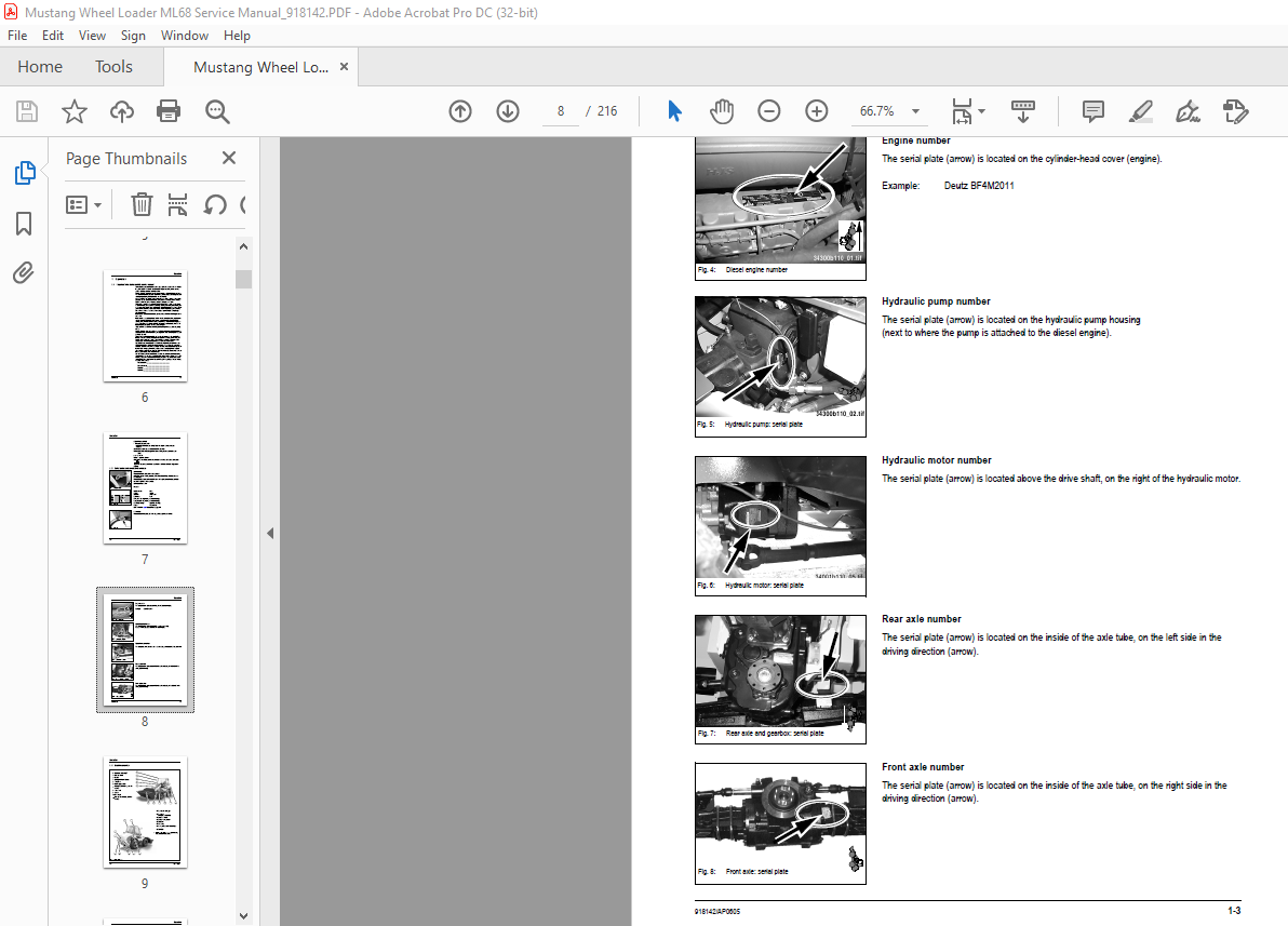
Serial plates and component numbers 1-2
Machine overview 1-4
Inside of cab: overview 1-5
Inside of cab: legend 1-6
Instrument panel, multifunctional lever and drive lever: overview 1-7
Instrument panel, multifunctional lever and drive lever: legend 1-8
Specifications
Frame 2-1
Engine 2-1
Power train 2-2
Axles 2-3
Brakes 2-3
Steering 2-3
Work hydraulics 2-4
Pilot control 2-4
Additional control circuit + high-flow control circuit (option) 2-4
Loader unit 2-5
Electrical system 2-5
Tires 2-8
Weights 2-9
Sound levels 2-9
Vibration 2-9
Hardware torques 2-10
Dimensions 2-11
Maintenance
Fluids and lubricants 3-1
Maintenance decal 3-2
Maintenance schedule Model ML68 (overview) 3-4
Maintenance items 3-7
Introduction 3-7
Fuel system 3-8
Engine lubrication system 3-11
Engine and hydraulics cooling system 3-14
Air filter 3-15
V-belt 3-17
Gearboxes and axles 3-18
Hydraulic system 3-24
Lubrication points 3-28
Attachments 3-29
Brake system 3-30
Tire care 3-31
Changing wheels 3-32
Electrical system 3-33
General maintenance work 3-36
Heating 3-39
Engine
Engine BF4M 2011: overview 4-1
Engine oil cooling 4-2
Fuel system 4-3
Checking and adjusting valve tip clearance 4-4
Replacing the fuel injection pump 4-5
Setting charge air pressure 4-10
Removing/mounting the cylinder head 4-12
Engine trouble 4-16
Power train
Variable displacement pump 12 – 25 mph (20 – 40 km/h) 5-1
Hydraulic motor – control element 12 mph (20 km/h) 5-2
Hydraulic motor – hydraulic connections 12 mph (20 km/h) 5-3
Power train diagram 12 mph (20 km/h) 5-4
ECO-Speed – hydraulic motor 25 mph (40 km/h) 5-5
ECO speed power train (25 mph [40 km/h]): diagram 5-7
Test report model 5-8
Towing and transporting the machine 5-9
Check and adjustment instructions 5-10
Drive electronics operator’s manual (SUSMIC) 5-17
Procedures (sensor) 5-18
Axles
Serial plate – axle 6-1
Front axle screw connections 6-2
Rear axle screw connections 6-3
Drain, fill and check plug – front axle 6-4
Drain, fill and check plug – rear axle 6-5
Tightening torques – front axle 6-6
Tightening torques – rear axle 6-7
Sealing work 6-8
Brakes
Brake circuit 7-1
Service brake 7-3
Steering
Steering circuit 8-1
Steering circuit 8-2
Hydraulic ports on servostat 8-3
Pressure relief valve – servostat: settings 8-3
Front/rear axle steering cylinder 8-4
Setting the steering sensors 8-5
Hydraulic system
Test report 9-1
Control valve connections: overview 9-2
Control valve: design 9-3
Pilot control unit: design 9-4
Valve block connections: overview 9-5
Pilot control circuit 9-6
Work hydraulics circuit 9-7
Load stabilizer circuit with hose burst valve 9-8
Load stabilizer: circuit diagram 9-9
Load stabilizer with hose burst valve: circuit diagram 9-10
Hose burst valve with load stabilizer: connections 9-11
Hose burst valve circuit 9-12
Hose burst valve circuit 9-13
4th control circuit (front/rear) 9-14
4th control circuit (front/rear) circuit 9-15
Lift cylinder: sealing work 9-16
Tilt cylinder: sealing work 9-17
Control cylinder (quickhitch frame): sealing work 9-18
Work hydraulics diagram: legend 9-20
Work hydraulics diagram 9-21
Electrical system
Ohm’s Law (current, voltage, resistance generates power) 10-1
Measuring equipment and methods 10-1
Terminal description 10-3
Cable color-coding 10-10
Relays 10-11
Electrical units 10-12
Fuse box on left and right of steering column 10-12
Main fuse box with relays 10-13
Relays 10-14
Steering electronics 10-15
Instrument panel, fuse box, relays: overview 10-16
Legend for wiring diagram 10-17
Wiring diagram 10-18
Legend for wiring harness 207749: engine – frame 10-19
Wiring harness: 207749: engine – frame 10-20
Legend for wiring harness 207750: cab 10-21
Wiring harness 207750: cab 10-22
Wiring harness 208562: control lever base (option) 10-23
Wiring harness 207968: control lever base (standard) 10-24
Wiring harness 207810: steering-column control lever 10-25
Wiring harness 208111: additional control circuit 10-26
Wiring harness 208609 (joystick) 10-27
Electronics between joystick and wiring harness 208609 10-27
Wiring harness 207539: rotating beacon (option) 10-28
Wiring harness 207539: front working light (option) 10-29
Wiring harness 208589: load stabilizer (option) 10-30
Wiring harness 208676: solenoid valve – load stabilizer (option) 10-31
Wiring harness 209185: inching sensor 10-32
Wiring harness 209185: crawler gear – potentiometer 10-33
Wiring harness 208563: numberplate light (option) 10-34
Wiring harness 208113: air-suspension operator’s seat (option) 10-35
Wiring harness: air conditioning (option) 10-36
Plug – SUSMIC 10-37
Relay assignment 10-38
Plug and socket connection: steering electronics – steering-column control lever
Plug and socket connection: fuse box and relay (left) 10-40
Plug and socket connection: fuse box and relay (right) 10-41
Plug and socket connection: cab 10-42
Plug and socket connection: instrument panel 10-42
Plug and socket connections: load stabilizer, speedometer 25 mph (40 km/h), front
socket 10-43
IMAGES PREVIEW OF THE MANUAL:
More products