$34
Mustang Articulated Loader AL 406 AL 506 Service Manual(50940008) – PDF DOWNLOAD
Mustang Articulated Loader AL 406 AL 506 Service Manual(50940008) – PDF DOWNLOAD
FILE DETAILS:
Mustang Articulated Loader AL 406 AL 506 Service Manual(50940008) – PDF DOWNLOAD
Language : English
Pages : 220
Downloadable : Yes
File Type : PDF
Size: 10.2 MB
DESCRIPTION:
Mustang Articulated Loader AL 406 AL 506 Service Manual(50940008) – PDF DOWNLOAD
INTRODUCTION
Safety Symbol
Manitou Americas, in cooperation with the Society of Automotive Engineers, has adopted this:
IMPORTANT: The word “IMPORTANT” indicates situations that can result in possible damage to the machine.
Contents and Use of this Manual
- This Service Manual contains information about the safe and proper maintenance, service and troubleshooting for the machine. Additionally, it contains basic operation information, but is not intended as a replacement for the Operator’s Manual that was provided with the machine.
- Refer to the Operator’s Manual for complete and detailed operation information. Major points of safe operation and maintenance are detailed in the Safety chapter of this manual.
- Follow the instructions in the Operator’s Manual Safety, Operation and Maintenance chapters, concerning accident prevention regulations, safety and occupational regulations, and machine and traffic regulations. Manitou Americas is not liable for damage resulting from the failure to follow these regulations.
Service Parts
When ordering service parts, provide complete information about the part and he quantity required. Also provide the model and serial numbers of the machine. For your safety and continued proper operation, use only genuine service parts
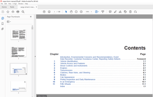
TABLE OF CONTENTS:
Mustang Articulated Loader AL 406 AL 506 Service Manual(50940008) – PDF DOWNLOAD
Chapter 1 — Introduction1
Chapter 2 — Safety3
Mandatory Safety Shutdown Procedure 4
Before Starting 4
During Operation 5
Service Safety Practices 6
Fire Hazards 8
Crystalline Silica Exposure 8
Safety Decals 9
Hazard and Hazard Avoidance Symbols 9
Chapter 3 — Specifications 11
Fluid Capacities/Lubricants 11
Dimensions 12
Weights and Capacities 14
Engine 15
Hydraulics 15
Electrical System 15
Sound Levels 15
Wheels 16
FOPS 16
Chapter 4 — Maintenance17
Maintenance Introduction 17
Maintenance Schedule 18
Engine Maintenance 20
Air Cleaner 22
Engine Cooling System 23
Fuel System 25
Checking and Adjusting V-belt Tension 27
Air Conditioning Maintenance 28
Hydraulic System Maintenance 29
Planetary Axles 30
Brake Fluid Reservoir 32
Wheels and Tires 33
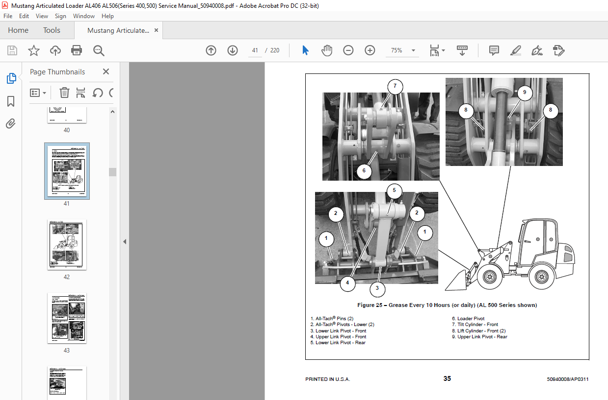
Lubrication 35
Electrical System 37
Storing the Loader 44
Maintenance Log 45
Chapter 5 — Operation49
Operation Safety 49
Controls and Switches 50
Instrument Panel and Indicators 52
Cab Controls (Cab only) 54
Warning Indicators 56
Operator’s Seat and Ignition Switch 57
Table of Contents
PRINTED IN USA ii 50940008/AP0311
Steering Column 58
Hand Throttle 59
Lift Arm Down-Stop59
Lift/Tilt Lock60
Chapter 6 — Chassis61
Tilting the Platform61
Lowering the Platform62
Repairing or Replacing Platform Switch 64
Hood Removal 65
Hood Installation 66
Center/Steering Bearing Removal 67
Center/Steering Bearing Installation 70
Lift Arm Removal 74
Lift Arm Installation 75
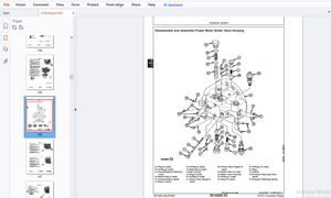
Attachment Plate Hydraulics Removal77
Attachment Plate Hydraulics Installation78
Chapter 7 — Engine79
Engine Removal79
Engine Installation83
Drive Coupling Removal 87
Drive Coupling Installation 87
Starter Removal 88
Starter Installation88
Chapter 8 — Cooling System 89
Radiator/Oil Cooler Removal 89
Radiator/Oil Cooler Installation 92
Chapter 9 — Axles95
Front Axle Removal 95
Front Axle Installation 98
Rear Axle Removal 100
Rear Axle Installation102
Chapter 10 — Hydraulics 103
Work Hydraulics Troubleshooting103
Hydrostatic Drive System106
Hydraulics Troubleshooting Diagnostic Flow Charts 107
Drive System Pressure Tests 121
Work System Pressure Tests 124
Steering Circuit Pressure Test 125
2-Spool Control Valve Removal126
3-Spool Control Valve Removal128
2-Spool Control Valve Installation131
3-Spool Control Valve Installation133
Lift/Tilt Lock, Power-A-Tach® System and Auxiliary Hydraulics Valve Locations 135
Table of Contents
50940008/AP0311 iii PRINTED IN USA
Lift Cylinder Removal 136
Lift Cylinder Installation 137
Tilt Cylinder Removal 138
Tilt Cylinder Installation 138
Steering Cylinder Removal 139
Steering Cylinder Installation 139
Hydraulic Cylinder Disassembly/Assembly 141
Gear/Work Hydraulic Pump Removal 149
Gear/Work Hydraulic Pump Installation 149
Piston/Drive Hydraulic Pump Removal 150
Piston/Drive Hydraulic Pump Installation 152
Hydrostatic Motor Removal 153
Hydrostatic Motor Installation 155
Steering Control Valve Removal 156
Steering Control Valve Removal 158
Steering Control Valve Installation 159
Steering Control Valve Installation 160
Raising Machine for Drive System Troubleshooting 161
AL 400 Series Hydraulic Schematic – SN 41250 and Up 163
AL 400 Series Hydraulic Schematic – SN 41249 and Before 164
AL 500 Series Hydraulic Schematic – SN 51242 and Up 165
AL 500 Series Hydraulic Schematic – SN 51241 and Before 166
Chapter 11 — Machine/Drive Controllers 167
Machine and Drive Controllers 167
Machine Controller 168
Drive Controller (Plus+1 Module) 172
Service Communication Kit and PLUS+1 GUIDE Service Tool Software 173
Plus+1 Service Tool Navigation/Overview 174
Software Log Monitoring Screen 175
Electrical Inputs/Outputs Monitoring Screen 176
Electrical Status Error Reporting Screen 177
System Definition Error Count/Timestamp Reset Screen 178
Drive Controller Pedal Calibration Parameters 179
Pump Profiling Screen/Drive “Creep” Adjustment 179
Pedal Calibration Procedure 181
Chapter 12 — Electrical System183
Battery Removal 183
Battery Installation 184
AL 400 Series (Serial Numbers 41250 and up) Complete Electrical Schematic 185
AL 400 Series (Serial Numbers 41250 and up) Steering Column Electrical Schematic 186
AL 400 Series (Serial Numbers 41250 and up) Chassis Electrical Schematic 187
AL 400 Series (Serial Numbers 41250 and up) Engine Electrical Schematic 188
AL 400 Series (Serial Numbers 41250 and up) FOPS, Power-A-Tach® and Tail Light Electrical
Schematic 189
AL 500 Series (Serial Numbers 51242 and up) Complete Electrical Schematic (Includes Air
Conditioning Option) 190
Table of Contents
PRINTED IN USA iv 50940008/AP0311
AL 500 Series (Serial Numbers 51242 and up) Steering Column Electrical Schematic (Includes Air
Conditioning Option) 191
AL 500 Series (Serial Numbers 51242 and up) Chassis Electrical Schematic (Includes Air Conditioning
Option) 192
AL 500 Series (Serial Numbers 51242 and up) Engine Electrical Schematic (Includes Air Conditioning
Option) 193
AL 500 Series (Serial Numbers 51242 and up) FOPS, CAB, Power-A-Tach® and Tail Light Electrical
Schematic (Includes Air Conditioning Option) 194
AL 400 Series (Serial Numbers 41249 and below), AL 500 Series (Serial Numbers 51241 and below)
Complete Electrical Schematic 195
Chapter 13 — Troubleshooting 197
Engine197
Indicator Lamps / Seals and Hoses 199
Hydraulic System200
Hydrostatic Drive System202
IMAGES PREVIEW OF THE MANUAL:
More products