$36
Mustang Articulated Loader AL106 AL206 AL306 Service Manual (918360) – PDF DOWNLOAD
Mustang Articulated Loader AL106 AL206 AL306 Service Manual (918360) – PDF DOWNLOAD
DESCRIPTION:
Mustang Articulated Loader AL106 AL206 AL306 Service Manual (918360) – PDF DOWNLOAD
INTRODUCTION
Safety Symbol
Manitou Americas, in cooperation with the Society of Automotive Engineers, has adopted this:
IMPORTANT:
The word “IMPORTANT” indicates situations that can result in possible damage to the machine
Contents and Use of this Manual
- This Service Manual contains information about the safe and proper maintenance, service and troubleshooting for the machine. Additionally, it contains basic operation information, but is not intended as a replacement for the Operator’s Manual that was provided with the machine.
- Refer to the Operator’s Manual for complete and detailed operation information. Major points of safe operation and maintenance are detailed in the Safety chapter of this manual. Follow the instructions in the Operator’s Manual Safety, Operation and Maintenance chapters, concerning accident prevention regulations, safety and occupational regulations, and machine and traffic regulations. Manitou Americas is not liable for damage resulting from the failure to follow these regulations.
TABLE OF CONTENTS:
Mustang Articulated Loader AL106 AL206 AL306 Service Manual (918360) – PDF DOWNLOAD
Chapter 1 — Introduction 1
Chapter 2 — Safety3
2-Post ROPS/FOPS Warning 4
Mandatory Safety Shutdown Procedure 4
Before Starting 4
During Operation 5
Provision for Stability/Avoiding Rollover Accidents 6
Electrical Energy 7
Service Safety Practices 7
Battery Hazards 8
Fire Hazards 8
Crystalline Silica Exposure 9
Safety Decals 9
Chapter 3 — Specifications11
Fluid Capacities/Lubricants 11
Dimensions – AL 300 and AL200 Series 13
Dimensions – AL 100 Series 15
SAE (Domestic) Weights and Capacities
AL 100 and AL 300 Series 17
ISO (EU) Weights and Capacities
AL 100, AL 200 and AL 300 Series 18
Engine 19
Hydraulics 19
Electrical System 19
Sound Levels 19
Wheels 19
Maximum Slopes of Operation 20
Wheel/Tire Sets 20
FOPS 20
Crane Lifting Chain Lengths 20
Vibration Levels 20
Vibration Information 21
Vibration Measurement and Actions 21
Chapter 4 — Maintenance 23
Maintenance Schedule 24
Check, Clean and Inspect 24
Leakage Check 25
Lubrication and Filter Changes 25
Functional Check 25
Engine Maintenance 26
Engine Oil 26
Air Cleaner 28
Engine Cooling System 29
Table of Contents
PRINTED IN USA ii 918360/BP1211
Fuel System31
Adding Fuel31
Changing Fuel Filter 31
Water Separator Maintenance32
Checking and Adjusting V-belt Tension 33
Hydraulic System Maintenance 34
Hydraulic Oil34
Planetary Axles 36
Changing Planetary Axle Oil (AL 300 Series Only) 36
Changing Axle Wheel-Hub Oil (AL 300 Series Only)36
Changing Axle Center Oil (AL 300 Series Only)37
Changing Axle Oil (AL 200 and AL 100 Series) 38
Checking Brake Fluid Reservoir Level (AL300 Series Only)38
Wheels and Tires39
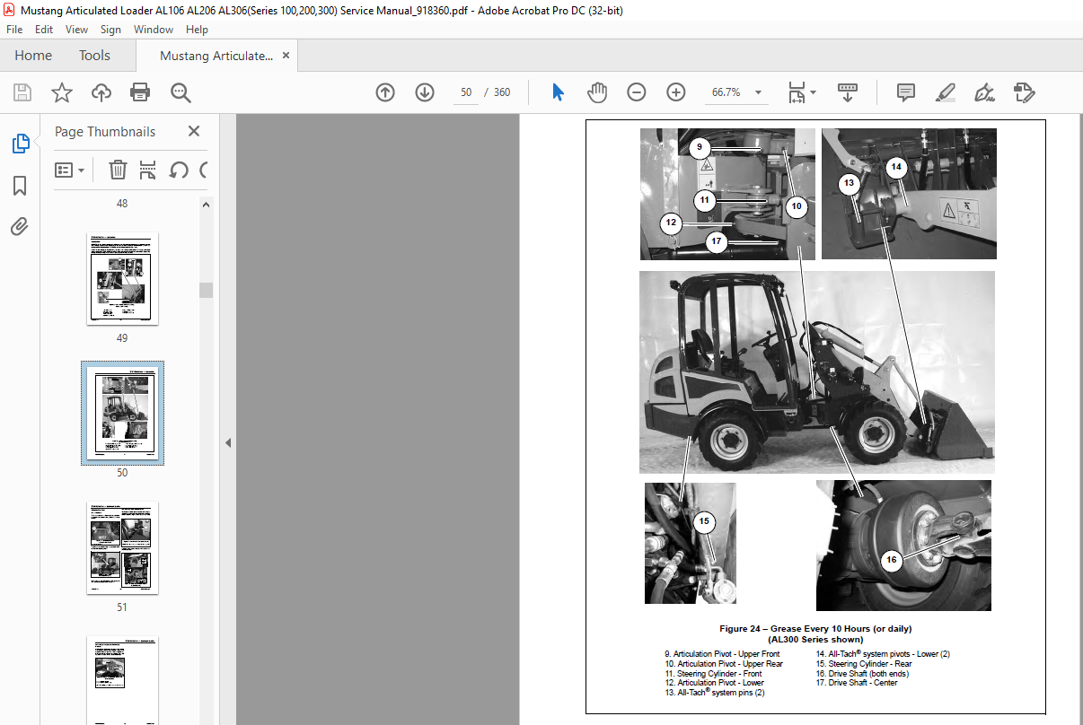
Lubrication40
Electrical System 42
Fuse Locations 42
Deluxe Steering Column44
Standard Steering Column 45
Fuse Blocks (s) – Engine Compartment 46
Battery47
Storing the Loader 49
Before Storage49
After Storage 49
Maintenance Log 50
Chapter 5 — Operation53
Operation Safety 53
Controls and Switches 54
Instrument Panel and Indicators 56
Cab Controls (Cab only) 58
Cab Environment Controls58
Cab Windshield Wiper Controls 58
Cab Dome Light58
Cab Defrost 58
Warning Indicators 59
Operator’s Seat and Ignition Switch 60
Seat Adjustment 60
Seatbelt60
Ignition Key Switch 60
Steering Column 61
Steering Column Adjustment61
Control Lever 61
Hand Throttle (AL300 Series only) 62
Lift Arm Down-Stop (AL200/300 Series)62
Boom and Bucket Lock (AL100 Series)63
Table of Contents
918360/BP1211 iii PRINTED IN USA
Chapter 6 — Chassis 65
Tilting the Platform 65
AL100 Series Platform Tilting 65
AL200 and 300 Series Platform Tilting 66
Lowering the Platform 67
AL100 Series Platform Lowering 67
AL200 and 300 Series Platform Lowering 68
Repairing or Replacing Platform Switch 70
Hood Removal 71
AL100 Series Hood Removal 71
AL200 and 300 Series Hood Removal 72
Hood Installation 73
AL100 Series Hood Installation 73
AL200 and 300 Series Hood Installation 74
Center/Steering Bearing Removal 75
AL100 Series Center/Steering Bearing Removal 75
AL200 and 300 Series Center/Steering Bearing Removal 78
Center/Steering Bearing Installation 82
AL100 Series Center/Steering Bearing Installation 82
AL200 and 300 Series Center/Steering Bearing Installation 85
Lift Arm Removal 89
AL100 Series Lift Arm Removal 90
AL200 and 300 Series Lift Arm Removal 91
Lift Arm Installation 93
AL100 Series Lift Arm Installation 93
AL200 and 300 Series Lift Arm Installation 96
Attachment Plate Removal 99
Attachment Plate Installation 100
Chapter 7 — Engine 101
Engine Removal 101
Engine Removal Preparation 101
AL100 Series Engine Removal 101
AL200 Series Engine Removal 108
AL300 Series Engine Removal 113
Engine Installation 118
AL100 Series Engine Installation 118
AL200 Series Engine Installation 125
AL300 Series Engine Installation 130
Engine Installation Completion 134
Drive Coupling Removal 135
Drive Coupling Installation 136
Starter Removal 137
Starter Installation 138
Table of Contents
PRINTED IN USA iv 918360/BP1211
Chapter 8 — Cooling System139
Radiator/Oil Cooler Removal 139
AL100 Series Radiator/Oil Cooler Removal 139
AL200 and 300 Series Radiator/Oil Cooler Removal 142
Radiator/Oil Cooler Installation145
AL100 Series Radiator/Oil Cooler Installation145
AL200 and 300 Series Radiator/Oil Cooler Installation148
Radiator/Oil Cooler Installation Completion150
Chapter 9 — Axles151
Service Brake Adjustment 151
AL 100/200 Series Service Brake Adjustment 151
AL 300 Series Service Brake Adjustment 151
Front Axle Removal153
AL100 Series Front Axle Removal153
AL200 Series Front Axle Removal155
AL300 Series Front Axle Removal157
Front Axle Installation 159
AL100 Series Front Axle Installation 159
AL200 Series Front Axle Installation 161
AL300 Series Front Axle Installation 162
Rear Axle Removal164
AL100 Series Rear Axle Removal164
AL200 Series Rear Axle Removal165
AL300 Series Rear Axle Removal167
Rear Axle Installation 168
AL100 Series Rear Axle Installation 168
AL200 Series Rear Axle Installation 170
AL300 Series Rear Axle Installation 171
Chapter 10 — Hydraulics 173
Work Hydraulics Troubleshooting 173
Hydrostatic Drive System175
Hydraulics Troubleshooting Diagnostic Flow Charts 178
Lift and Tilt Hydraulics Diagnostics – AL100 (SN 11257 and up), AL200 (SN 21244 and Up),
AL300 (SN 31365 and Up) Series 178
Steering Hydraulics Diagnostics – AL100 (SN 11257 and up), AL200 (SN 21244 and Up),
AL300 (SN 31365 and Up) Series 180
Auxiliary Hydraulics Diagnostics – AL100 (SN 11257 and up), AL200 (SN 21244 and Up),
AL300 (SN 31365 and Up) Series 182
Work and Steering Hydraulics Diagnostics – AL100 (SN 11256 and before), AL200 (SN 21243 and before),
AL300 (SN 31364 and before) Series184
Drive Hydraulics Diagnostics – AL100 (All Serial Numbers) and AL200 (SN 21243 and before) Series 186
Drive Hydraulics Diagnostics – AL300 and AL200 (SN 21244 and Up) Series 188
Hydraulic Piston/Drive Pump Diagnostics – AL100 (SN 11257 and up) Series190
Hydraulic Piston/Drive Pump Diagnostics – AL200 (SN 21244 and up) Series192
Hydraulic Piston/Drive Pump Diagnostics – AL100 (SN 11256 and before),
AL200 (SN 21243 and before) Series 194
Table of Contents
918360/BP1211 v PRINTED IN USA
Hydraulic Piston/Drive Pump Diagnostics – AL300 Series 196
Hydrostatic Motor Diagnostics – AL100 (SN 11257 and up), AL200 (SN 21244 and up) Series 198
Hydrostatic Motor Diagnostics – AL100 (SN 11256 and before), 200 (SN 21243 and before) Series 200
Hydrostatic Motor Diagnostics – AL300 Series 202
Series Hydrostatic Motor Diagnostics – AL100 (SN 11257 and up) Series 204
Hydrostatic Motor Diagnostics – AL200 (SN 21244 and up) Series 206
Hydrostatic Motor Diagnostics – AL100 (SN 11256 and before), AL200 (SN 21243 and before) Series 208
Hydrostatic Motor Diagnostics – AL300 Series 210
Drive System Electrical Diagnostics 212
Drive System Components — AL100 Series 214
Drive System Components — AL200 Series 215
Drive System Components — AL300 Series 216
Charge Pump/Pilot Pressure Tests 217
Charge Pump Pressure Test – AL100 Series, SN 11257 and Up 217
Charge Pump Pressure Test – AL100 Series, SN 11256 and Before 218
Charge Pump and Pilot Pressure Test – AL200 Series, SN 21244 and Up 219
Charge Pump and Pilot Pressure Test – AL200 Series, SN 21243 and Before 219
Charge Pump Pressure Test – AL300 Series, SN 31365 and Up 220
Charge Pump Pressure Test – AL300 Series, SN 31364 and Before 221
AL 300 Series Pilot Pressure Test – AL300 Series, SN 31365 and Up 222
AL 300 Series Pilot Pressure Test – AL300 Series, SN 31364 and Before 222
Drive Pressure Tests 223
Drive Pressure Test – AL100 Series 223
Drive Pressure Test – AL200 Series 224
Drive Pressure Test – AL300 Series 225
Work System Pressure Tests 226
Work Pressure Test – AL100 Series 226
Work Pressure Test – AL200 Series 227
Work Pressure Test – AL300 Series 228
Work Cylinder Leakage Test 229
2-Spool Control Valve Removal 230
AL 100 Series — Serial Numbers 11257 and Up
AL 200 Series — Serial Numbers 21244 and Up
AL 300 Series — Serial Numbers 31365 and Up 230
AL 300 Series 230
3-Spool Control Valve Removal 232
AL 100 Series — Serial Numbers 11256 and Below
AL 200 Series — Serial Numbers 21243 and Below
AL 300 Series — Serial Numbers 31364 and Below 232
2-Spool Control Valve Installation 234
AL 100 Series — Serial Numbers 11257 and Up
AL 200 Series — Serial Numbers 21244 and Up
AL 300 Series — Serial Numbers 31365 and Up 234
AL 300 Series 234
3-Spool Control Valve Installation 236
AL 100 Series — Serial Numbers 11256 and Below
AL 200 Series — Serial Numbers 21243 and Below
AL 300 Series — Serial Numbers 31364 and Below 236
Table of Contents
PRINTED IN USA vi 918360/BP1211
Lift/Tilt Lock, Power-A-Tach® System and Auxiliary Hydraulics Valve Locations238
Lift/Tilt Lock Valves 238
Power-A-Tach® System Hydraulic Valve238
Auxiliary Hydraulic Valve238
Lift Cylinder Removal 239
AL100 Series Lift Cylinder Removal 239
AL200 and 300 Series Lift Cylinder Removal 240
Lift Cylinder Installation 241
AL100 Series Lift Cylinder Installation241
AL200 and 300 Series Lift Cylinder Installation243
Tilt Cylinder Removal 244
AL100 Series Tilt Cylinder Removal 244
AL200 and 300 Series Tilt Cylinder Removal245
Tilt Cylinder Installation246
AL100 Series Tilt Cylinder Installation246
AL200 and 300 Series Tilt Cylinder Installation 247
Steering Cylinder Removal248
Steering Cylinder Installation 249
Hydraulic Cylinder Disassembly/Assembly251
Cylinder Disassembly 251
Cylinder Assembly255
Gear/Work Hydraulic Pump Removal258
Gear/Work Hydraulic Pump Installation 260
Piston/Drive Hydraulic Pump Removal 262
AL100 Series Piston/Drive Hydraulic Pump Removal262
AL200 Series Piston/Drive Hydraulic Pump Removal262
AL300 Series Piston/Drive Hydraulic Pump Removal – Serial Numbers 31365 and Up264
AL300 Series Piston/Drive Hydraulic Pump Removal – Serial Numbers 31364 and Below 266
Piston/Drive Hydraulic Pump Installation 269
AL100 Series Piston/Drive Hydraulic Pump Installation 269
AL200 Series Piston/Drive Hydraulic Pump Installation 269
AL300 Series Piston/Drive Hydraulic Pump Installation – Serial Numbers 31365 and Up 271
AL300 Series Piston/Drive Hydraulic Pump Installation – Serial Numbers 31364 and Below273
Hydrostatic Motor Removal 276
AL100 Series Hydrostatic Motor Removal 276
AL200 Series Hydrostatic Motor Removal 277
AL300 Series Hydrostatic Motor Removal – Serial Numbers 31365 and Up278
AL300 Series Hydrostatic Motor Removal – Serial Numbers 31364 and Below 279
Hydrostatic Motor Installation281
AL100 Series Hydrostatic Motor Installation281
AL200 Series Hydrostatic Motor Installation282
AL300 Series Hydrostatic Motor Installation – Serial Numbers 31365 and Up 282
AL300 Series Hydrostatic Motor Installation – Serial Numbers 31364 and Below284
Steering Control Valve Removal285
AL100 Series Steering Control Valve Removal 285
AL200 and 300 Series Steering Control Valve Removal 286
Table of Contents
918360/BP1211 vii PRINTED IN USA
Steering Control Valve Installation 287
AL100 Series Steering Control Valve Installation 287
AL200 and 300 Series Steering Control Valve Installation 288
Raising Machine for Drive System Troubleshooting 290
AL100 Series Hydraulic Schematic – SN 11257 and Up 293
AL100 Series Hydraulic Schematic – SN 11256 and Before 294
AL200 Series Hydraulic Schematic – SN 21244 and Up 295
AL200 Series Hydraulic Schematic – SN 21243 and Before 296
AL300 Series Hydraulic Schematic – SN 31365 and Up 297
AL300 Series Hydraulic Schematic – SN 31364 and Before 298
Chapter 11 — Electrical System299
Battery Removal 299
Battery Installation 300
Machine Controller 302
Machine Controller LED/Indicator Assignments 302
Machine Controller Logic 304
AL100 Series Complete Electrical Schematic – With Standard Steering Column (SN 11257 and Up) 307
AL100 Series Complete Electrical Schematic – With Deluxe Steering Column (SN 11257 and Up) 308
AL100 Series Standard Steering Column Electrical Schematic (SN 11257 and Up) 309
AL100 Series Deluxe Steering Column Electrical Schematic (SN 11257 and Up) 310
AL100 Series Chassis Electrical Schematic (SN 11257 and Up) 311
AL100 Series Engine Electrical Schematic (SN 11257 and Up) 312
AL100 Series Road Homologation Electrical Schematic (SN 11257 and Up) 313
AL200 Series Complete Electrical Schematic – With Standard Steering Column (SN 21244 and Up) 314
AL200 Series Complete Electrical Schematic – With Deluxe Steering Column (SN 21244 and Up) 315
AL200 Series Standard Steering Column Electrical Schematic (SN 21244 and Up) 316
AL200 Series Deluxe Steering Column Electrical Schematic (SN 21244 and Up) 317
AL200 Series Chassis Electrical Schematic (SN 21244 and Up) 318
AL200 Series Engine and 4-Post ROPS Electrical Schematic (SN 21244 and Up) 319
AL200 Series Road Homologation Electrical Schematic (SN 21244 and Up) 320
AL100 and 200 Series Complete Electrical Schematic – Without Road Homologation
(AL100 Series – SN 10255-11256; AL200 Series – SN 20235-21243) 321
AL100 and 200 Series Complete Electrical Schematic – Without Road Homologation
(AL100 Series – SN 10254 and before; AL200 Series – SN 20234 and before) 322
AL100 and 200 Series Complete Electrical Schematic – With Road Homologation
(AL100 Series – SN 10255-11256; 200 Series – SN 20235-21243) 323
AL100 and 200 Series Complete Electrical Schematic – With Road Homologation
(AL100 Series – SN 10254 and Before; 200 Series – SN 20234 and Before) 324
AL300 Series Complete Electrical Schematic (SN 31365 and Up) 325
AL300 Series Steering Column Electrical Schematic (SN 31365 and Up) 326
AL300 Series Engine Schematic (SN 31365 and Up) 327
AL300 Series Chassis Electrical Schematics (SN 31365 and Up) 328
AL300 Series Tail Light, Radio, Power-A-Tach® System Harness 4-Post ROPS and
Cab Electrical Schematics (SN 31365 and Up) 329
AL300 Series Complete Electrical Schematic (SN 30310-31364) 330
AL300 Series Complete Electrical Schematic (SN 30309 and Before) 331
Table of Contents
PRINTED IN USA viii 918360/BP1211
Chapter 12 — Troubleshooting 333
Engine 333
Indicator Lamps / Seals and Hoses 335
Indicator Lamps 335
Seals and Hoses335
Hydraulic System336
Hydrostatic Drive System339
Electrical 340
IMAGES PREVIEW OF THE MANUAL:
More products