$33
Mustang Compact Excavator 5003ZT Sevice Manual (918178) – PDF DOWNLOAD
Mustang Compact Excavator 5003ZT Sevice Manual (918178) – PDF DOWNLOAD
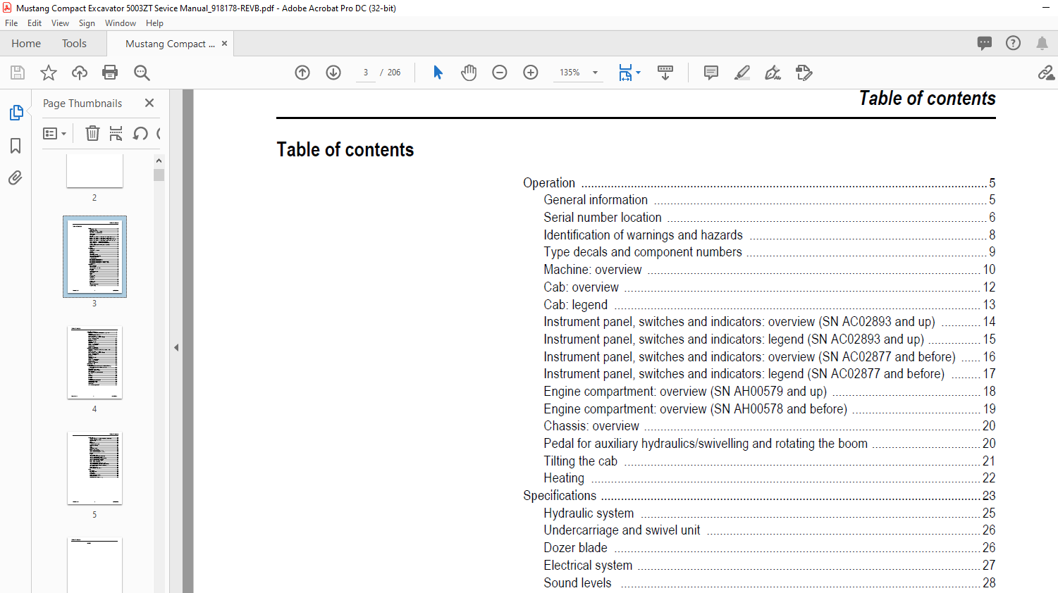
TABLE OF CONTENTS:
Mustang Compact Excavator 5003ZT Sevice Manual (918178) – PDF DOWNLOAD
Operation …………………………………………………………………………………………………………… 5
General information ……………………………………………………………………………………….. 5
Serial number location ……………………………………………………………………………………. 6
Identification of warnings and hazards ……………………………………………………………… 8
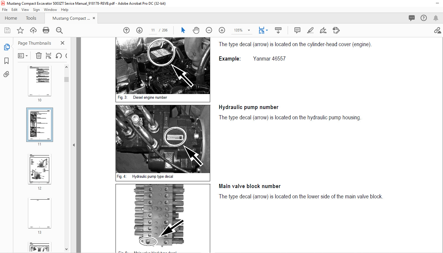
Type decals and component numbers ………………………………………………………………. 9
Machine: overview ……………………………………………………………………………………….. 10
Cab: overview ……………………………………………………………………………………………… 12
Cab: legend ………………………………………………………………………………………………… 13
Instrument panel, switches and indicators: overview (SN AC02893 and up) ………… 14
Instrument panel, switches and indicators: legend (SN AC02893 and up) ……………. 15
Instrument panel, switches and indicators: overview (SN AC02877 and before) …… 16
Instrument panel, switches and indicators: legend (SN AC02877 and before) ……… 17
Engine compartment: overview (SN AH00579 and up) ……………………………………… 18
Engine compartment: overview (SN AH00578 and before) ………………………………… 19
Chassis: overview ………………………………………………………………………………………… 20
Pedal for auxiliary hydraulics/swivelling and rotating the boom …………………………… 20
Tilting the cab ……………………………………………………………………………………………… 21
Heating ………………………………………………………………………………………………………. 22
Specifications ……………………………………………………………………………………………………. 23
Hydraulic system …………………………………………………………………………………………. 25
Undercarriage and swivel unit ……………………………………………………………………….. 26
Dozer blade ………………………………………………………………………………………………… 26
Electrical system ………………………………………………………………………………………….. 27
Sound levels ………………………………………………………………………………………………. 28
Coolant compound table ……………………………………………………………………………….. 28
Model-specific tightening torques …………………………………………………………………… 29
General tightening torques ……………………………………………………………………………. 29
5003ZT dimensions ……………………………………………………………………………………… 32
Lift capacity table with short dipper arm ………………………………………………………….. 33
Lift capacity table with long dipper arm ……………………………………………………………. 34
Lift capacity table with short dipper arm and counterweight ……………………………….. 35
Lift capacity table with long dipper arm and counterweight ………………………………… 36
Bucket geometry ………………………………………………………………………………………….. 37
Maintenance …………………………………………………………………………………………………….. 39
Fluids and lubricants ……………………………………………………………………………………. 39
Maintenance decal ……………………………………………………………………………………….. 41
Maintenance schedule (overview) ………………………………………………………………….. 43
Introduction …………………………………………………………………………………………………. 47
Fuel system ………………………………………………………………………………………………… 48
Engine lubrication system ……………………………………………………………………………… 52
Cooling system ……………………………………………………………………………………………. 55
Air filter ……………………………………………………………………………………………………….. 58
V-belt …………………………………………………………………………………………………………. 60
Pressure check ……………………………………………………………………………………………. 64
Test report ………………………………………………………………………………………………….. 71
Hydraulic system …………………………………………………………………………………………. 75
Travel drive …………………………………………………………………………………………………. 80
Tracks ………………………………………………………………………………………………………… 81
Lubrication work …………………………………………………………………………………………… 83
Electrical system ………………………………………………………………………………………….. 86
Cab ……………………………………………………………………………………………………………. 90
General maintenance work ……………………………………………………………………………. 91
Long-term storage ……………………………………………………………………………………….. 93
Table of contents
Printed in U.S.A. 2 918178BP0409
Table of contents
Engine (SN AH00579 and up) ………………………………………………………………………………95
Engine marked 4TNV88-BPNS (SN AH00579 and up): overview ………………………..95
Fuel system ………………………………………………………………………………………………….97
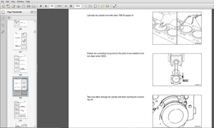
Preparing for cylinder head removal ………………………………………………………………..98
Checking and adjusting valve tip clearance ………………………………………………………98
Removing/Tightening order for cylinder head bolts ……………………………………………99
Checking the injection nozzles ………………………………………………………………………100
Checking the nozzle jet ………………………………………………………………………………..100
Injection timing ……………………………………………………………………………………………101
Adjusting engine speeds ………………………………………………………………………………104
Compression ………………………………………………………………………………………………105
Checking the coolant thermostat …………………………………………………………………..105
Checking the thermal switch …………………………………………………………………………106
Oil pressure switch ………………………………………………………………………………………106
Checking the coolant circuit ………………………………………………………………………….106
Engine (SN AD07125 and before) ………………………………………………………………………107
Engine marked 4TNV88-PNS (SN AD07125 and before): overview …………………..107
Fuel system ………………………………………………………………………………………………..109
Checking and adjusting valve tip clearance …………………………………………………….110
Removing/Tightening order for cylinder head bolts ………………………………………….110
Checking the injection nozzles ………………………………………………………………………111
Checking the nozzle jet ………………………………………………………………………………..112
Injection timing ……………………………………………………………………………………………112
Adjusting engine speeds ………………………………………………………………………………116
Compression ………………………………………………………………………………………………116
Checking the coolant thermostat …………………………………………………………………..116
Checking the thermal switch …………………………………………………………………………117
Oil pressure switch ………………………………………………………………………………………117
Checking the coolant circuit ………………………………………………………………………….118
Engine Troubleshooting ……………………………………………………………………………………119
Hydraulic system ………………………………………………………………………………………………121
Hydraulic pump: PVD-2B-41BP-16G5-4713F (SN AH00579 and up)
PVD-2B-44BP-16G5-4713F (AD07125 and before) ……………………………………121
Main valve block …………………………………………………………………………………………125
Drive counterbalancing system ……………………………………………………………………..130
Regeneration – dipper arm section ………………………………………………………………..132
Bucket pre-tension ………………………………………………………………………………………132
Flow rate adjustment for auxiliary hydraulics …………………………………………………..133
Pilot valves …………………………………………………………………………………………………134
Valves ……………………………………………………………………………………………………….140
Travel drive ………………………………………………………………………………………………..143
Swivel unit ………………………………………………………………………………………………….146
Swivel joint …………………………………………………………………………………………………150
Breather filter ……………………………………………………………………………………………..151
Troubleshooting the hydraulic system ……………………………………………………………152
Hydraulics diagram (legend) …………………………………………………………………………153
Hydraulics diagram 5003ZT ………………………………………………………………………….155
Options diagram ………………………………………………………………………………………….156
Main valve block diagram 5003ZT …………………………………………………………………157
DESCRIPTION:
Mustang Compact Excavator 5003ZT Sevice Manual (918178) – PDF DOWNLOAD
Operation
General information
- Your decision to purchase the Mustang compact excavator was a good one. We are sure that your decision was carefully considered and that you are looking forward to many years of reliable performance from the machine. Mustang Company has invested much time and effort in developing its lines of equipment. The equipment you have purchased is built with a great deal of pride, and designed to provide long life, efficient operation, durability and dependability.
- Modern machinery has become more sophisticated and, with that in mind, Mustang Company asks that you read and COMPLETELY understand the contents of this manual and become familiar with the new machine, BEFORE attempting to service it. This manual was developed specifically for the machine you have purchased. The information within is for your assistance in preparing, adjusting, maintaining and servicing the machine.
- More important, this manual provides a service plan for safe and proper servicing of the machine. Refer to the Table of Contents for an outline (by chapters) of this manual. Use the Index, located at the back of this manual, for specific chapter and topic/page number references.
- If the machine is resold, Mustang Company recommends that this manual be given to the new owner. If the machine was purchased “used,” or if the owner’s address has changed, please provide your Mustang dealer or Mustang Company with the owner’s name and current address, along with the machine model and serial number. This will allow the registered owner information to be updated, so that the owner can be notified directly in case of an important product issue, such as a safety update program.
- “Right” and “left” are determined from the position of sitting in the operator’s seat, facing forward. Mustang Company reserves the right to make changes or improvements in the design or construction of any part without incurring the obligation to install such changes on any unit previously delivered. Throughout this manual information is provided that is introduced by the word
- Be sure to read carefully and comply with the message or directive given. Following this information will improve your maintenance efficiency, help you to avoid costly breakdowns or unnecessary damage, and extend your machine’s life. Operational safety and readiness of the machine depend partially on maintenance and service of the machine. This is why regular maintenance and service work is absolutely necessary. Extensive maintenance and repair work must always be carried out by a qualified technician with appropriate training.
- Insist on using Mustang original service parts when carrying out maintenance and repair work. This ensures operational safety and readiness of your machine, and maintains its value. Our wide dealership network stands ready to provide any assistance required, including genuine Mustang service parts.
- All parts should be obtained from or ordered through your Mustang dealer. Give complete information about the part as well as the model number and serial number of your machine. Record numbers, in the spaces provided, as a handy record for quick reference
IMAGES PREVIEW OF THE MANUAL:
More products