$36
Mustang Compact Excavator ME12002 Service Manual (909768 ) – PDF DOWNLOAD
Mustang Compact Excavator ME12002 Service Manual (909768 ) – PDF DOWNLOAD
DESCRIPTION:
Mustang Compact Excavator ME12002 Service Manual (909768 ) – PDF DOWNLOAD
Introduction
- For your safety and continued proper operation, use only genuine MUSTANG® service parts. When ordering service parts, specify the correct part number, full description, quantity required, the unit model number and serial number. The model and serial number decal for this unit is located on the left chassis upright.
- “Right” and “Left” are determined from a position sitting on the seat and facing forward. Mustang Company reserves the right to make changes or improvements in the design or construction of any part of the unit without incurring the obligation to install such changes on any previously delivered units.
- Refer to the abbreviations table located on this page for the various fastener descriptions. Standard attaching hardware torque values are also provided on the inside back cover.
- If a part requires lubrication or a nonstandard torque value, it will be specified behind the part number description in parenthesis. Items shown in the parts list that do not have part numbers are shown for reference purposes only and are NOT available for purchase. Dimensions are in inches unless otherwise specified.
TABLE OF CONTENTS:
Mustang Compact Excavator ME12002 Service Manual (909768 ) – PDF DOWNLOAD
Chapter 1
Technical Data 1
General Dimensions 1
General Specifications 3
Bucket Geometry 4
Maximum Permissible Loads on Dipper Arm 5
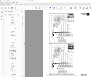
Lift Capacity Chart 6
Hydraulic System Specifications 7
John Deere 4045TF270 and Yanmar 4TNE106T-NS Specifications 9
Tightening Torques 11
Port Codes: Main Valve Block 11
Hydraulic Joints and Dry Assembly 14
Hydraulic Screw Joints and Dry Assembly 15
High Quality Screws and MA High Quality Screw Joints 17
Type Relative for High Quality Screw Joints 18
Oil Grades: Ambient Temperature 20
Chapter 2
Maintenance 21
Maintenance Chart 21
Check, Clean and Inspect 21
Fluid and Filter Changes 24
Air Conditioning 25
Functional Check 25
Leakage Check 25
Lubrication Check 26
Lubrication 27
Recommended Lubricants 27
Lubricants 28
General Information 28
Care and Servicing 28
Maintenance Safety 29
Hydraulic System 30
Hydraulic Pump Pressure Checklist 31
Hydraulic Pump Part Inspection 34
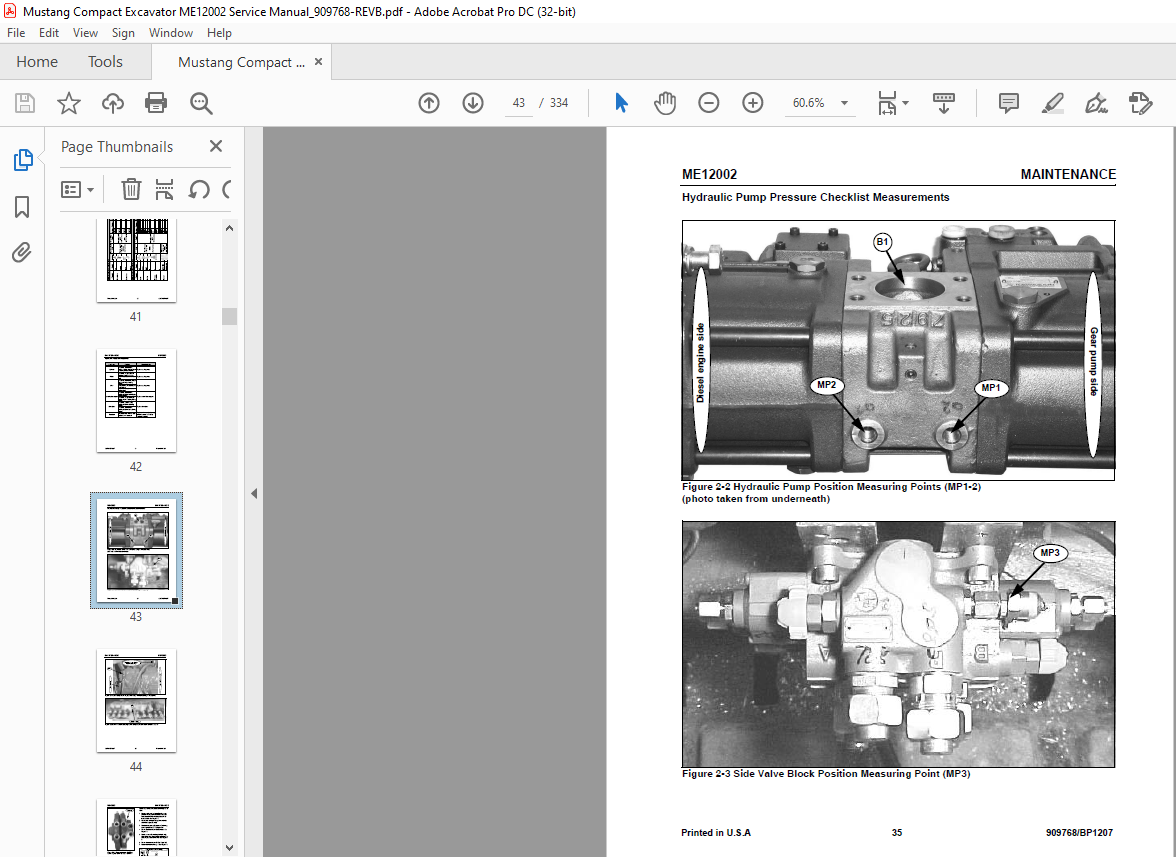
Hydraulic Pump Pressure Checklist Measurements 35
Checking Hydraulic Oil Level: New Style 38
Checking Hydraulic Oil Level: Old Style 39
Changing Hydraulic Oil: New Style 40
Changing Hydraulic Oil: Old Style 41
Diesel Engine 42
Engine Oil/Filter Change Maintenance Schedules 42
Fuel System 43
Air Cleaner 47
Air Cleaner (SN AC02633 and up) 47
TABLE OF CONTENTS
TABLE OF CONTENTS ME12002
909768/BP1207 ii Printed in USA
Air Cleaner (SN AB03158 and before) 48
Coolant System 48
Checking Coolant Level (SN AC02633 and up) 48
Checking Coolant Level (SN AB00473-AB03158) 49
Chapter 3
Hydraulic System 51
Hydraulic System Diagram 51
Hydraulic System Diagram Legend 51
Hydraulic System Diagram 52
Hydraulic System Component Positions 53
Hydraulic Pump Specifications 57
Hydraulic Pump Specifications
Diagram Legend 57
Hydraulic Pump Function Designation 59
Hydraulic Pump Port Codes 60
Hydraulic Pump Section Description 61
Hydraulic Pump Valve Designation 62
Testing Hydraulic Pressure 64
Hydraulic Pump Components 67
Hydraulic Schematic 67
Hydraulic Pump Rotation Group 68
Hydraulic Pump Regulator Functions 69
Hydraulic Pump Regulator Performance Diagrams 71
Power or Torque Summation and Negative Displacement Control 72
Function Torque Summation Control 73
Negative Control Regulation 79
Disassembling and Assembling the Hydraulic Pump 85
General Information 85
Tools 85
Disassembling the Hydraulic Pump 86
Assembling the Hydraulic Pump 91
Hydraulic Pump Tightening Torques 97
Regulator (front) 98
Power Shift Proportional Control 99
Regulator (rear) 100
Gear Pump 101
Hydraulic System 102
Hydraulic Diagram – Main Valve Block 103
Hydraulic Pump Port Codes 104
Hydraulic Pump Function Summation 106
Negative Control System 107
Functions 107
Valve Structure 108
Fine Metering 109
Spool Identification Codes 110
ME12002 TABLE OF CONTENTS
Printed in USA iii 909768/BP1207
Main Valve Block – Section A 110
Main Valve Block – Section B 110
Main Valve Block – Section C 111
Valves 112
Load Check Valve 112
Circuit Pressure Protection 113
Main Relief Valve 114
Shock Suction Valve 114
Operating Pilot Pressure 115
Operating Main Relief 116
Port Relief Valve 116
Boom 118
Boom Cylinders Port Connections 118
Raising the Boom (high speed operation) 120
Raising the Boom (low speed operation) 122
Lowering the Boom 123
Regeneration Circuit 124
Dipper Arm Section 126
Dipper Arm Control 128
Retracting the Dipper Arm Cylinder 129
Lowering the Dipper Arm Cylinder (with heavy loads) 131
Lowering the Dipper Arm Cylinder (with light loads) 132
Bucket Section 133
Swing Section 135
Boom Swing Control 136
Auxiliary Hydraulics Section 138
Auxiliary Hydraulics Function 139
Section Drive Left 140
Section Drive Right 140
Section Drive Counterbalancing
System (straight travel) 141
Drive Counterbalancing System
Function (straight travel) 141
Straight Travel Spool (no additional actuation) 143
Straight Travel Spool (with additional actuation) 144
Side Valve Block Regulation 146
Disassembling and Assembling the Control Valve 147
General Information 147
Tools 147
Disassembling the Control Valve 147
Inspecting the Control Valve 151
Assembling the Control Valve 151
Joystick 154
Joystick Structure 154
Hydraulic Piloting System 155
Joystick Pilot Valve Overview 155
Disassembling the Joystick 155
Assembling the Joystick 160
TABLE OF CONTENTS ME12002
909768/BP1207 iv Printed in USA
Joystick Tightening Torque 165
Hydraulic Pedals 166
General Information 166
Pilot Control Pedals: Control Valve for Auxiliary Hydraulics 167
Connection Ports, Driving Pedals 169
Pilot Control Pedals – Auxiliary Hydraulics, Dozer Blade 169
Port Connection – Dozer Blade Pedal 171
Disassembling the Pilot Control Pedal 171
Assembling the Pilot Control Pedal 176
Hydraulic System Components 181
Pilot Oil Supply Unit 181
Side Valve Block 182
Shuttle Valve Block 183
Switch Valve 184
Load Lowering Valve 185
Hydraulic Oil Tank 186
Breather Filter 186
Driving Unit 187
Swing Motor (Swivel Unit) 188
Hydraulic Diagram 188
Swing Motor Structure 189
Disassembling the Swing Motor 190
Assembling the Swing Motor 194
Chapter 4
John Deere Engine 4045TF270 (SN AC02633 and up) 203
John Deere Engine Model 4045TF270 Overview 203
Fuel System 205
Servicing the Components 206
Checking Valve Tip Clearance 206
Servicing the Cylinder Head 207
Removing the Cylinder Head 207
Installing the Cylinder Head 210
Servicing the Fuel Injection Pump 214
Removing the Fuel Injection Pump 214
Installing the Fuel Injection Pump 215
Servicing the Fuel Injection
Nozzles 217
Removing the Fuel Injection Nozzles 217
Testing the Fuel Injection Nozzles 218
Disassembling the Fuel Injection Nozzles 220
Assembling the Fuel Injection Nozzles 221
Checking Compression 225
Servicing the Thermostat 226
Inspecting the Thermostat 226
Servicing the Cooling System 227
Checking for Water Leakage 227
ME12002 TABLE OF CONTENTS
Printed in USA v 909768/BP1207
Chapter 5
Yanmar Engine 4TNE106T-NS (SN AB00473-AB03158) 229
Yanmar Engine Model 4TNE106T-NS Overview 229
Fuel System 233
Servicing the Components 234
Checking Valve Tip Clearance 234
Measuring Compression Pressure 236
Inspecting the Thermostat 236
Inspecting the Thermoswitch 237
Checking for Cooling System Water Leakage 237
Checking the V-belt Tension 238
Inspecting the Fuel Injection Valve and Spray Pattern 238
Coolant Circuit 243
Servicing the Water Pump 244
Adjusting the Radiator Fan 244
Servicing the Starter 245
Disassembling the Starter 245
Assembling the Starter 248
Servicing the Alternator 251
Removing the Alternator 251
Disassembling the Alternator 251
Assembling the Alternator 253
Installing the Alternator 254
Servicing the Fuel Feed Pump 254
Disassembling the Fuel Feed Pump 254
Inspecting Fuel Feed Pump Parts 255
Assembling the Fuel Feed Pump 255
Servicing the Fuel Injection Pump 256
Removing the Fuel Injection Pump 256
Disassembling the Fuel Injection Pump 257
Servicing the Fuel Injection Pump 257
Servicing the Fuel Injection Pump Gears 258
Assembling the Fuel Injection Pump 259
Installing the Fuel Injection Pump 259
Servicing the Governor 260
Disassembling the Governor Cover 260
Assembling the Governor Cover 260
Disassembling the Governor Housing 260
Assembling the Governor Housing 260
Servicing the Tappet and
Camshaft 261
Disassembling the Tappet and
Camshaft 261
Inspecting the Tappet and Camshaft Parts 262
Assembling the Tappet and Camshaft 264
Servicing the Cylinder Head 265
Disassembling the Cylinder Head 265
Assembling the Cylinder Head 266
TABLE OF CONTENTS ME12002
909768/BP1207 vi Printed in USA
Servicing the Gear Train and Camshaft 267
Disassembling the Gear Train and Camshaft 267
Assembling the Gear Train and Camshaft 267
Assembling the Camshaft 271
Servicing the Cylinder Block 272
Disassembling the Cylinder Block 272
Inspecting and Measuring Cylinder Block Parts 274
Assembling the Cylinder Block 275
Lubrication System 284
Servicing the Trochoid Pump 285
Servicing the Turbocharger 287
Turbocharger Overview 288
Turbocharger Components 288
Checking Waste Gate Valve Opening Pressure and Lift 289
Turbocharger Service Standards 290
Chapter 6
Troubleshooting 291
John Deere Engine Model 4045TF270 (SN AC02633 and up) 291
Yanmar Engine Model 4TNE106T-NS (SN AB00473-AB03158) 293
Troubleshooting the Starter 300
Troubleshooting the Alternator 301
General Information 302
Indicator Lamps 302
Seals and Hoses 302
Traveling Gear 302
Bucket, Boom and Dozer Blade 303
Hydraulic Pump 303
Inspecting Filter and Drain Oil 303
Inspecting for Abnormal Vibration and Noise 304
Measuring Pressure of Each Part 304
Chapter 7
Electrical System 307
Electric Wiring Diagram Legend 307
Electric Wiring Diagrams 309
Electric Wiring Connections 312
Right Armrest Connections 312
Right and Left Armrest Connections 314
Motor Cable Tree and Armrest Connections 315
Chassis and Armrest Connections 315
Engine RPM Controllers, Buttons, Motors and Pump Regulator Connections 316
Electric Speed Control Unit 317
Setting the Proportional Controller 318
Function 318
Adjustment 318
Time Ramp 318
IMAGES PREVIEW OF THE MANUAL:
More products