$36
Mustang Compact Excavator ME5002 ME6002 ME6502 Service Manual_918172 – PDF DOWNLOAD
Mustang Compact Excavator ME5002 ME6002 ME6502 Service Manual_918172 – PDF DOWNLOAD
FILE DETAILS:
Mustang Compact Excavator ME5002 ME6002 ME6502 Service Manual_918172 – PDF DOWNLOAD
Language : English
Pages : 158
Downloadable : Yes
File Type : PDF
Size: 7.87 MB
DESCRIPTION:
Mustang Compact Excavator ME5002 ME6002 ME6502 Service Manual_918172 – PDF DOWNLOAD
Introduction
- For your safety and continued proper operation, use only genuine Mustang® service parts. When ordering service parts, specify the correct part number, full description, quantity required, the unit model number, and serial number.
- The model and serial number decal for this unit is located on the left chassis upright. “Right” and “Left” are determined from a position sitting on the seat and facing forward. Mustang Company reserves the right to make changes or improvements in the design or construction of any part of the unit without incurring the obligation to install such changes on any previously delivered units.
- Refer to the abbreviations table located on this page for the various fastener descriptions. Standard attaching hardware torque values are also provided on the inside back cover. If a part requires lubrication or a nonstandard torque value, it will be specified behind the part number description in parenthesis.
- Items shown in the parts list that do not have part numbers are shown for reference purposes only and are NOT available for purchase. Dimensions are in inches unless otherwise specified.
TABLE OF CONTENTS:
Mustang Compact Excavator ME5002 ME6002 ME6502 Service Manual_918172 – PDF DOWNLOAD
Table of contents
A Technical data
Dimensions A2
Bucket and Geometry A4
Lift capacity charts A6
Hydraulic settings A12
Auxiliary hydraulics A13
Diesel engine settings A14
B Maintenance
Maintenance schedule B2
Maintenance – general B5
Lubricants B6
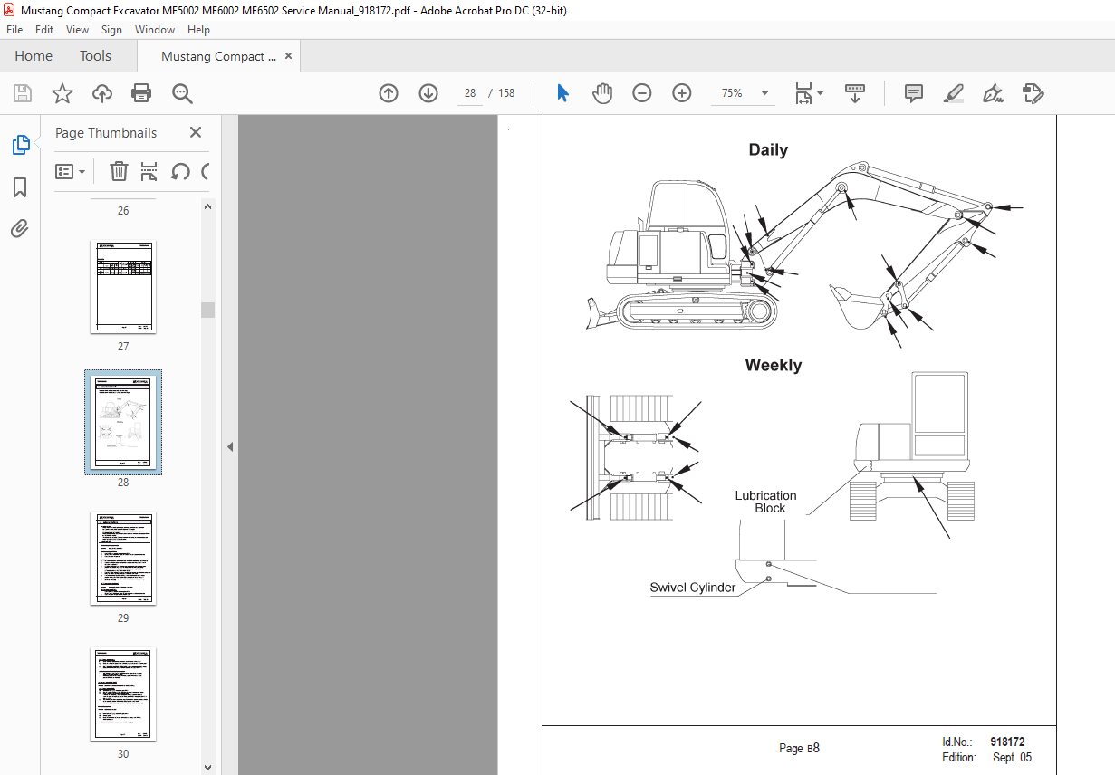
Lubrication chart B8
Hydraulic system B9
Hydraulic pump B20
Hose burst protection valve B21
Drive unit B22
Swivel unit B23
Diesel engine B24
Undercarriage B35
Hydraulic oil tank B36
C Hydraulic
Hydraulic system / diagrams C2
Position of components C6
Hydraulic pump C9
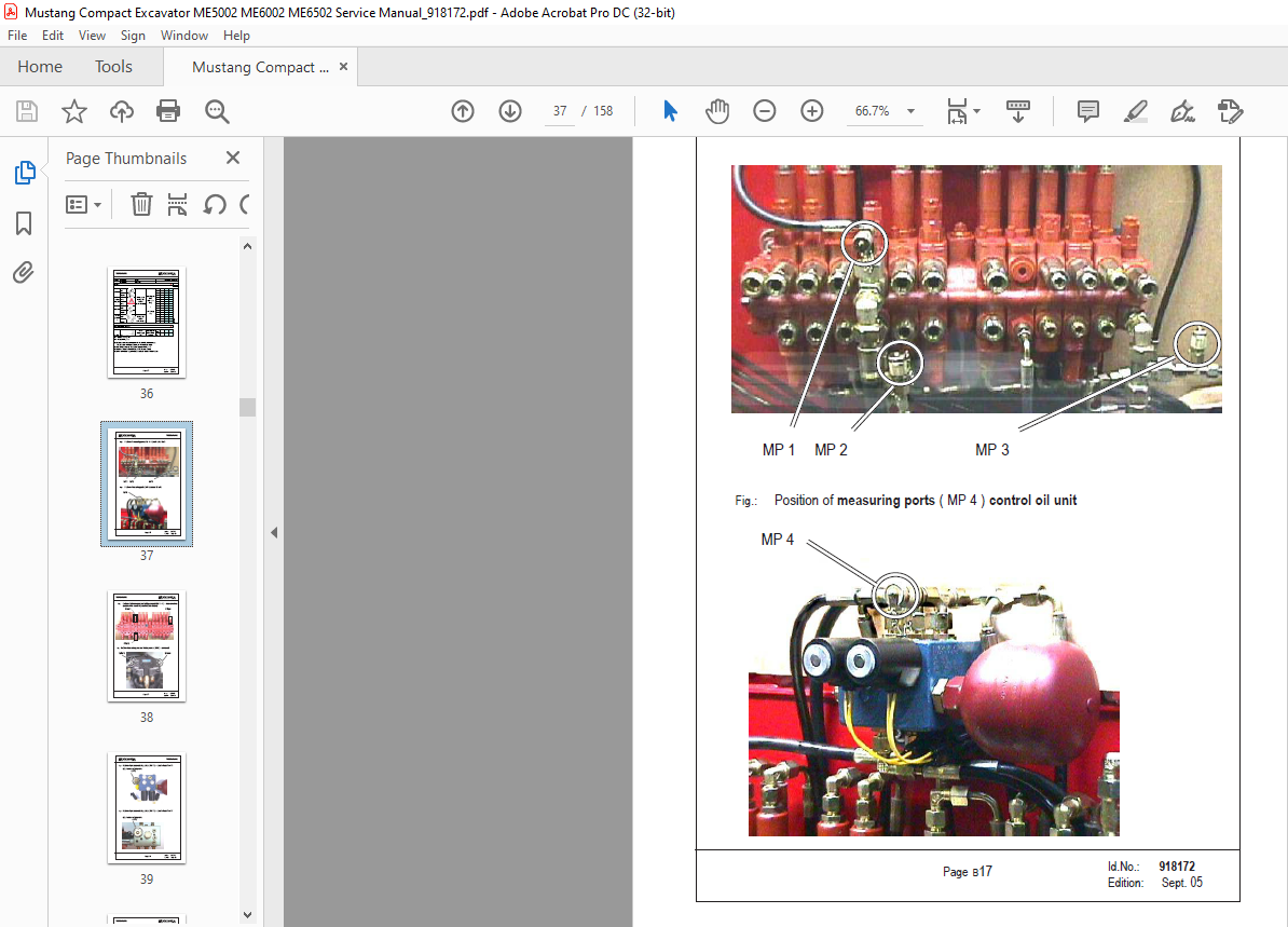
Pilot oil supply unit C12
Main valve block C17
Pilot control valves C32
Swivel unit C38
Shuttle valve block C44
Drive unit C47
Swivel joint C50
Switch valve C51
Tank C52
D Diesel Engine
Diesel engine specifications D2
Fuel line diagram D3
Battery D4
Radiator D5
Cylinder head bolt tightening / loosening order D5
E Electrical
Electrical system diagrams E2
Electrical system component positions E6
Electrical system diagrams E12
Electrical connections E21
Fuse box E27
F Operating Elements
Machine overview F2
Component description F3
Cab equipment and controls F4
Lifting the excavator F10
IMAGES PREVIEW OF THE MANUAL:
More products