$36
Mustang Compact Excavator ME6003 Service Manual (918175) – PDF DOWNLOAD
Mustang Compact Excavator ME6003 Service Manual (918175) – PDF DOWNLOAD
DESCRIPTION:
Mustang Compact Excavator ME6003 Service Manual (918175) – PDF DOWNLOAD
Introduction
- For your safety and continued proper operation, use only genuine MUSTANG® service parts. When ordering service parts, specify the correct part number, full description, quantity required, the unit model number and serial number. The model and serial number decal for this unit is located on the left chassis upright.
- “Right” and “Left” are determined from a position sitting on the seat and facing forward. Mustang Company reserves the right to make changes or improvements in the design or construction of any part of the unit without incurring the obligation to install such changes on any previously delivered units.
- Refer to the abbreviations table located on this page for the various fastener descriptions. Standard attaching hardware torque values are also provided on the inside back cover.
- If a part requires lubrication or a nonstandard torque value, it will be specified behind the part number description in parenthesis. Items shown in the parts list that do not have part numbers are shown for reference purposes only and are NOT available for purchase. Dimensions are in inches unless otherwise specified.
Operation
1.1 Important information about this service manual
This service manual contains important information about safely servicing the machine, correctly and economically. It serves as a reference for experienced users, helps to avoid hazardous situations, and reduces repair costs and downtimes. Additionally, the reliability and the service life of the machine will be increased by following the instructions in this
manual.
Proper and careful work is the best protection against accidents!
Operational safety and readiness of the machine depends not only upon operator skill, but also upon proper maintenance and service. Always use original Mustang service parts when performing maintenance and repair work. This ensures operational safety and readiness of the machine, and maintains its value
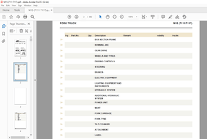
TABLE OF CONTENTS:
Mustang Compact Excavator ME6003 Service Manual (918175) – PDF DOWNLOAD
Operation
Important information about this service manual …………………………………………….. 1-1
Abbreviations/symbols ………………………………………………………………………………… 1-1
Identification of warnings and hazards ………………………………………………………….. 1-2
Designated use and exemption from liability ………………………………………………….. 1-2
Type labels and component numbers ……………………………………………………………. 1-3
Machine: overview ……………………………………………………………………………………… 1-5
Cab Equipment and Controls ……………………………………………………………………….. 1-6
Instrument panel, switches and indicators ……………………………………………………… 1-8
Engine compartment …………………………………………………………………………………. 1-10
Chassis: overview …………………………………………………………………………………….. 1-11
SAE/ISO operating controls selector valve …………………………………………………… 1-12
Tilting the cab ………………………………………………………………………………………….. 1-13
SAE operating controls (standard) ………………………………………………………………. 1-14
ISO operating controls (selectable) …………………………………………………………….. 1-15
Boom slew/auxiliary hydraulics pedal ………………………………………………………….. 1-16
Dozer blade …………………………………………………………………………………………….. 1-17
Throttle lever ……………………………………………………………………………………………. 1-17
Operator’s seat adjustments ………………………………………………………………………. 1-18
Ventilation ……………………………………………………………………………………………….. 1-19
Cab door latch release ………………………………………………………………………………. 1-20
Interior light ……………………………………………………………………………………………… 1-21
Tool kit and cab jack handle ………………………………………………………………………. 1-21
Cab heat control ………………………………………………………………………………………. 1-21
Recirculated air mode ……………………………………………………………………………….. 1-22
Hydraulics/swiveling and boom rotation pedal adjustment ……………………………… 1-22
Battery master switch ……………………………………………………………………………….. 1-22
Specifications
Chassis …………………………………………………………………………………………………….. 2-1
Engine ………………………………………………………………………………………………………. 2-1
Capacities ……………………………………………………………………………………………. 2-2
Engine Tightening Torques ……………………………………………………………………. 2-2
Hydraulic system ……………………………………………………………………………………….. 2-3
Auxiliary hydraulics oil flow* …………………………………………………………………… 2-3
Screwable hose burst valve ……………………………………………………………………. 2-3
Undercarriage/swivel unit ……………………………………………………………………………. 2-4
Dozer blade ………………………………………………………………………………………………. 2-4
Electrical system ………………………………………………………………………………………… 2-4
Sound levels ……………………………………………………………………………………………… 2-6
Fluid capacities ………………………………………………………………………………………….. 2-7
Coolant compound table ……………………………………………………………………………… 2-7
Specific tightening torques …………………………………………………………………………… 2-7
General tightening torques ………………………………………………………………………….. 2-8
Dimensions ……………………………………………………………………………………………… 2-10
Lift Capacities ………………………………………………………………………………………….. 2-11
Geometry ………………………………………………………………………………………………… 2-15
Maintenance
General information care and servicing …………………………………………………………. 3-1
Maintenance decal symbols ………………………………………………………………………… 3-3
Maintenance decal ……………………………………………………………………………………… 3-4
Maintenance schedule ………………………………………………………………………………… 3-5
General Maintenance …………………………………………………………………………………. 3-7
Cab interior ………………………………………………………………………………………….. 3-8
Exterior of the machine ………………………………………………………………………….. 3-8
I-2 918175/AP0605
Engine compartment ……………………………………………………………………………… 3-8
Screw connections and attachments ……………………………………………………….. 3-8
Pivots and hinges …………………………………………………………………………………. 3-8
Lubrication ………………………………………………………………………………………………… 3-9
Lubrication strip ………………………………………………………………………………….. 3-10
Engine …………………………………………………………………………………………………….. 3-10
Changing engine oil and filter …………………………………………………………………….. 3-11
Air cleaner service ……………………………………………………………………………………. 3-12
Fuel system ……………………………………………………………………………………………… 3-13
Coolant system ………………………………………………………………………………………… 3-16
Electrical system ………………………………………………………………………………………. 3-17
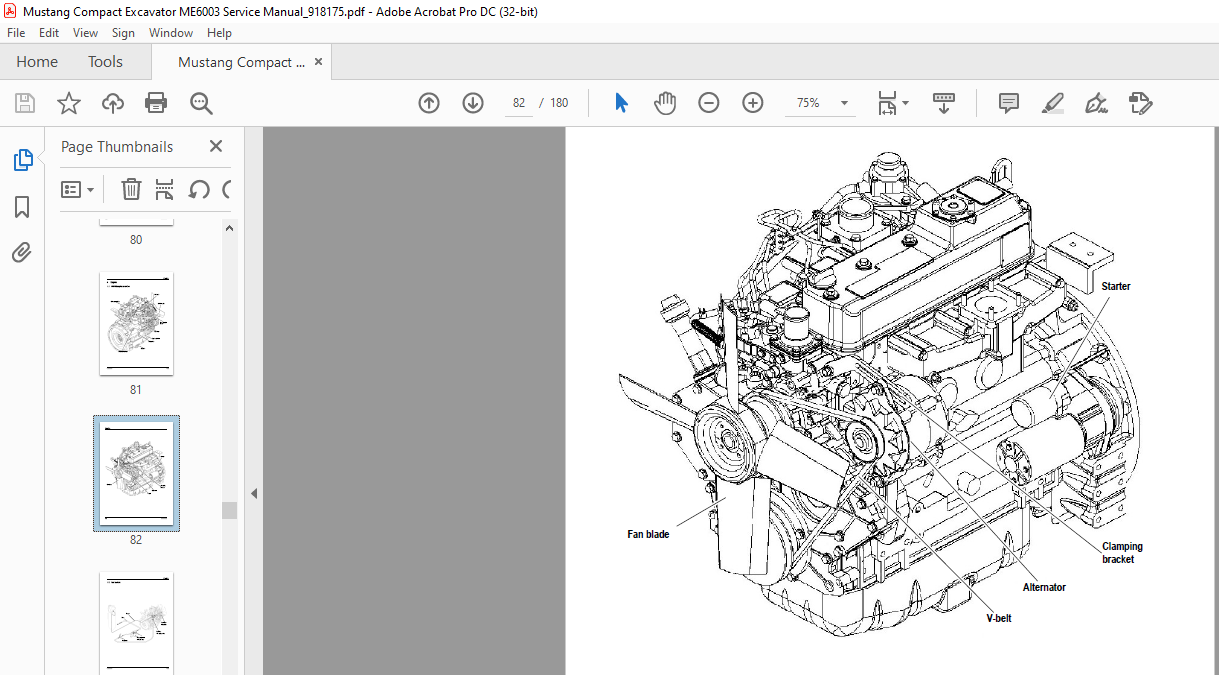
Alternator …………………………………………………………………………………………… 3-20
Checking & adjusting V-belt tension ……………………………………………………………. 3-20
Fluids and lubricants …………………………………………………………………………………. 3-23
Pressure check ………………………………………………………………………………………… 3-24
General ……………………………………………………………………………………………… 3-24
Pressure check of variable displacement pump P1 ………………………………….. 3-24
Pressure check of variable displacement pump P2 ………………………………….. 3-25
Checking the gear pump P3 pressure ……………………………………………………. 3-26
Checking pilot control pressure …………………………………………………………….. 3-27
Gear motor secondary pressure limiting valve ………………………………………… 3-28
Measuring ports: overview ……………………………………………………………………. 3-28
Primary pressure limiting valves ……………………………………………………………. 3-29
Test report ……………………………………………………………………………………………….. 3-30
Hydraulic system ………………………………………………………………………………………. 3-33
Cab heater filter ……………………………………………………………………………………….. 3-36
Replacing the inside heater filter …………………………………………………………… 3-36
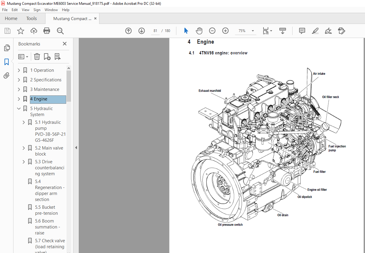
Engine
4TNV98 engine: overview ……………………………………………………………………………. 4-1
Fuel system ……………………………………………………………………………………………….. 4-3
Removing the cylinder-head cover ……………………………………………………………….. 4-4
Checking and adjusting valve tip clearance ……………………………………………………. 4-4
Cylinder head bolt tightening order ……………………………………………………………….. 4-6
Checking the injection nozzles ……………………………………………………………………… 4-6
Pressure check …………………………………………………………………………………….. 4-6
Checking the nozzle jet ……………………………………………………………………………….. 4-7
Injection timing …………………………………………………………………………………………… 4-8
Adjusting engine idle …………………………………………………………………………………… 4-9
Compression ……………………………………………………………………………………………… 4-9
Checking the coolant thermostat ………………………………………………………………… 4-10
Checking the thermal switch ………………………………………………………………………. 4-10
Oil pressure switch ……………………………………………………………………………………. 4-11
Checking the coolant circuit ……………………………………………………………………….. 4-11
Engine troubleshooting ……………………………………………………………………………… 4-12
Hydraulic System
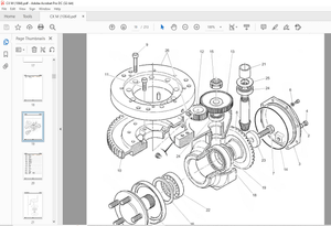
Hydraulic pump PVD-3B-56P-21G5-4626F ……………………………………………………. 5-1
Pump unit: exploded view ………………………………………………………………………. 5-3
Control oil unit ………………………………………………………………………………………. 5-4
Main valve block ………………………………………………………………………………………… 5-5
Ports …………………………………………………………………………………………………… 5-5
Legend ………………………………………………………………………………………………… 5-6
Main valve block diagram ………………………………………………………………………. 5-7
Pressure limiting valves …………………………………………………………………………. 5-8
Pump assignment …………………………………………………………………………………. 5-9
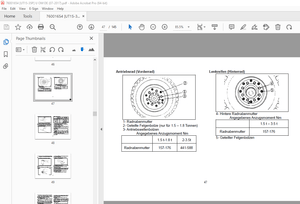
Drive counterbalancing system …………………………………………………………………… 5-10
Pump assignment for drive counterbalancing ………………………………………….. 5-10
918175/AP0605 I-3
Drive counter-balancing system diagram ……………………………………………….. 5-11
Regeneration – dipper arm section ……………………………………………………………… 5-12
Bucket pre-tension ……………………………………………………………………………………. 5-12
Boom summation – raise …………………………………………………………………………… 5-13
Check valve (load retaining valve) ………………………………………………………………. 5-14
Flow rate adjustment of auxiliary hydraulics …………………………………………………. 5-15
Secondary pressure limiting valves for the auxiliary hydraulics (option) …………… 5-16
Pilot valves ………………………………………………………………………………………………. 5-17
Joystick ……………………………………………………………………………………………… 5-17
Pilot valve (driving) ……………………………………………………………………………… 5-18
Pilot valve for auxiliary hydraulics ………………………………………………………….. 5-20
Pilot valve for dozer blade ……………………………………………………………………. 5-21
Valves …………………………………………………………………………………………………….. 5-22
7/3 directional valve (changeover valve) ………………………………………………… 5-22
4/3 directional valve …………………………………………………………………………….. 5-23
Shuttle valve block ………………………………………………………………………………. 5-24
Changeover valve for SAE/ISO controls (option) …………………………………….. 5-25
Travel drive ……………………………………………………………………………………………… 5-26
Function …………………………………………………………………………………………….. 5-27
2nd speed range function …………………………………………………………………….. 5-27
Swivel unit ……………………………………………………………………………………………….. 5-29
Parking brake function …………………………………………………………………………. 5-30
Swivel joint ………………………………………………………………………………………………. 5-33
Breather filter …………………………………………………………………………………………… 5-33
Troubleshooting in the hydraulic system ……………………………………………………… 5-34
Hydraulics diagram A4 ………………………………………………………………………………. 5-35
Hydraulics diagram (legend) ………………………………………………………………………. 5-36
Hydraulics diagram …………………………………………………………………………………… 5-37
Main valve block diagram ………………………………………………………………………….. 5-38
Hydraulics diagram with 3rd control circuit (option) ………………………………………. 5-39
Main valve block diagram with 3rd control circuit (option) ……………………………… 5-40
Electrical system
Ohm’s Law (current, voltage, resistance); power …………………………………………….. 6-1
Measuring equipment, measuring methods ……………………………………………………. 6-1
Cable color coding ……………………………………………………………………………………… 6-2
Relays ………………………………………………………………………………………………………. 6-3
Use, mode of function ……………………………………………………………………………. 6-3
Electric units ……………………………………………………………………………………………… 6-3
Fuse box in instrument panel ……………………………………………………………………….. 6-3
Main fuse box with relays ……………………………………………………………………………. 6-4
Relays ………………………………………………………………………………………………………. 6-4
Socket ………………………………………………………………………………………………………. 6-5
Tip switches on joystick ………………………………………………………………………………. 6-5
Left-hand side joystick …………………………………………………………………………… 6-5
Right-hand side joystick …………………………………………………………………………. 6-5
I-4 918175/AP0605
Instrument panel: overview ………………………………………………………………………….. 6-6
Switches: overview …………………………………………………………………………………….. 6-7
Alternator ………………………………………………………………………………………………….. 6-7
Starter ………………………………………………………………………………………………………. 6-8
Wiring harness 1000109629: cab roof …………………………………………………………… 6-9
Wiring diagram version 1 …………………………………………………………………………… 6-10
Wiring diagram version 1: legend ……………………………………………………………….. 6-11
Wiring diagram version 1 …………………………………………………………………………… 6-12
Wiring diagram version 2: legend ……………………………………………………………….. 6-13
Wiring diagram version 2 …………………………………………………………………………… 6-14
Wiring harness 1000109624 (legend): engine – chassis ………………………………… 6-15
Wiring harness 1000109624: engine – chassis …………………………………………….. 6-16
Wiring harness 1000109630 (legend) version 1: switches ……………………………… 6-17
Wiring harness 1000109630 version 1: switches …………………………………………… 6-18
Wiring harness (legend) version 2: switches A4 ……………………………………………. 6-19
Wiring harness version 2: switches ……………………………………………………………… 6-20
Wiring harness 1000109628: armrest ………………………………………………………….. 6-21
Wiring harness 1000116138: boom working light ………………………………………….. 6-22
Options
Air conditioning ………………………………………………………………………………………….. 7-1
Specific safety instructions …………………………………………………………………….. 7-1
Installation: overview …………………………………………………………………………….. 7-2
Components ………………………………………………………………………………………… 7-2
Counterweight ……………………………………………………………………………………………. 7-8
Specifications ……………………………………………………………………………………….. 7-8
Extended dipper arm …………………………………………………………………………………… 7-8
Specifications ……………………………………………………………………………………….. 7-8
Control circuit hydraulic coupling connections ………………………………………………… 7-9
3rd control circuit connections ……………………………………………………………………… 7-9
Auxiliary hydraulics connections …………………………………………………………………. 7-10
Fuel-filling pump ……………………………………………………………………………………….. 7-11
Ports …………………………………………………………………………………………………. 7-12
Central lubrication system ………………………………………………………………………….. 7-12
Safe load indicator D (safety valve for boom) ……………………………………………….. 7-17
Safe load indicator F (safety valves for boom and dipper arm) ……………………….. 7-19
Position ……………………………………………………………………………………………… 7-19
IMAGES PREVIEW OF THE MANUAL:
More products