$35
Mustang Compact Excavator ME7503ZT Service Manual_918165 – PDF DOWNLOAD
Mustang Compact Excavator ME7503ZT Service Manual_918165 – PDF DOWNLOAD
DESCRIPTION:
Mustang Compact Excavator ME7503ZT Service Manual_918165 – PDF DOWNLOAD
Introduction
- For your safety and continued proper operation, use only genuine MUSTANG® service parts. When ordering service parts, specify the correct part number, full description, quantity required, the unit model number and serial number. The model and serial number decal for this unit is located on the left chassis upright. ‘
- “Right” and “Left” are determined from a position sitting on the seat and facing forward. Mustang Company reserves the right to make changes or improvements in the design or construction of any part of the unit without incurring the obligation to install such changes on any previously delivered units.
- Refer to the abbreviations table located on this page for the various fastener descriptions. Standard attaching hardware torque values are also provided on the inside back cover.’
- If a part requires lubrication or a nonstandard torque value, it will be specified behind the part number description in parenthesis. Items shown in the parts list that do not have part numbers are shown for reference purposes only and are NOT available for purchase. Dimensions are in inches unless otherwise specified. NOTE
TABLE OF CONTENTS:
Mustang Compact Excavator ME7503ZT Service Manual_918165 – PDF DOWNLOAD
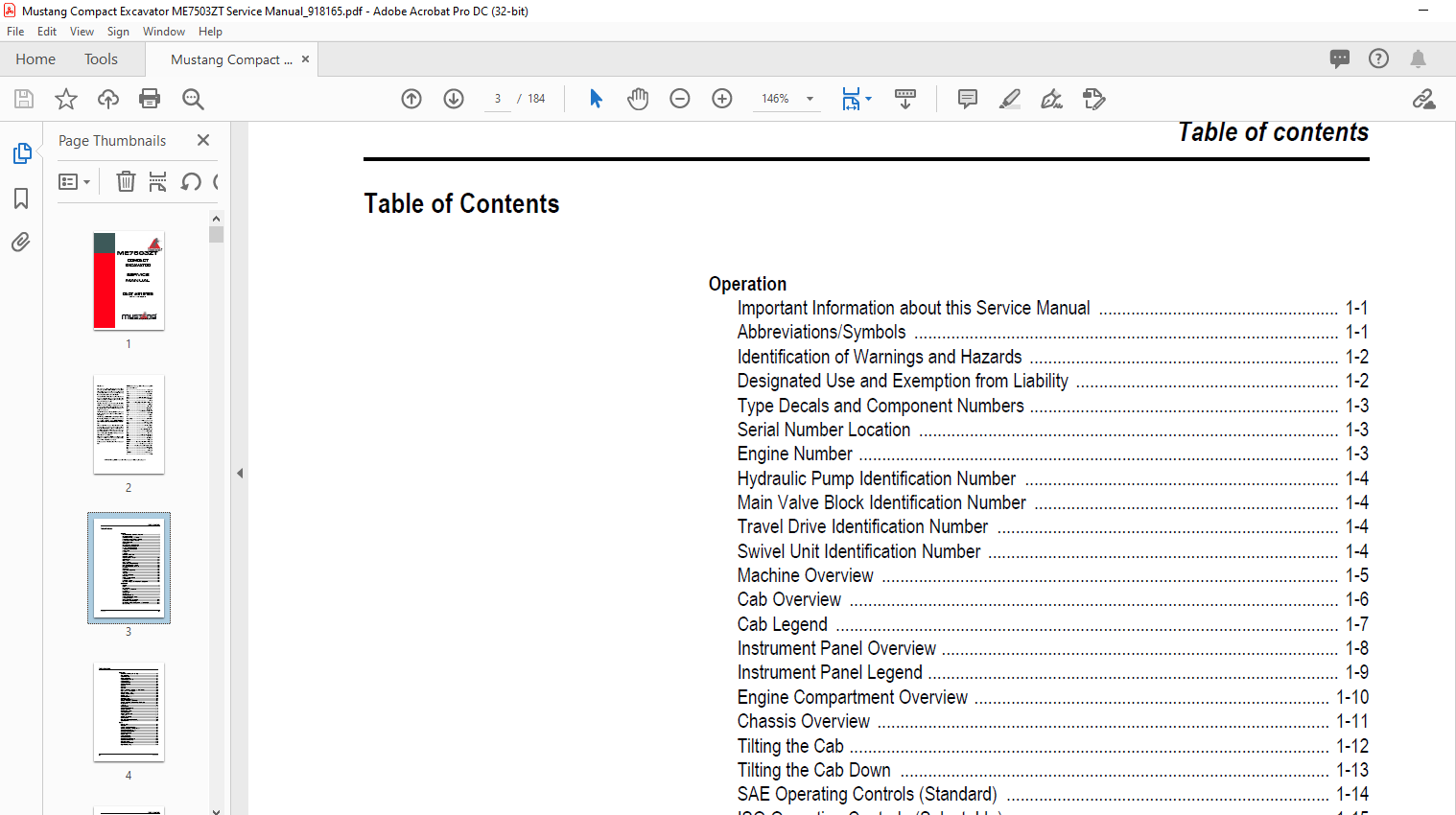
Operation
Important Information about this Service Manual ……………………………………………. 1-1
Abbreviations/Symbols ……………………………………………………………………………….. 1-1
Identification of Warnings and Hazards …………………………………………………………. 1-2
Designated Use and Exemption from Liability ………………………………………………… 1-2
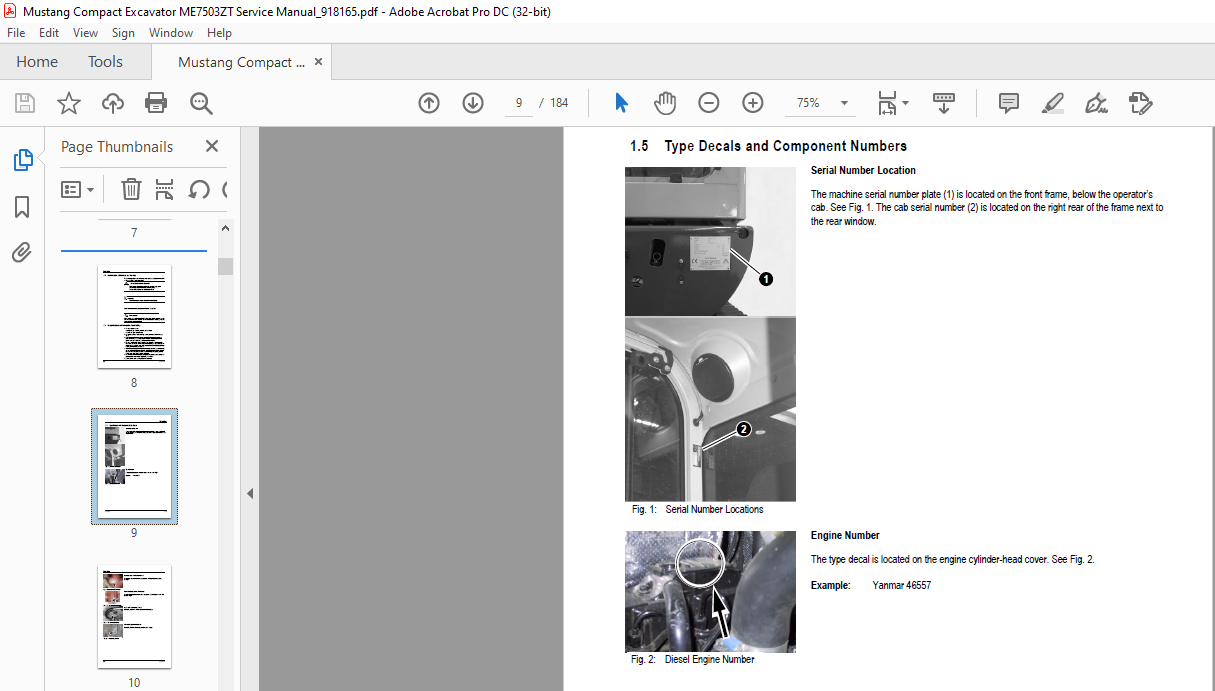
Type Decals and Component Numbers …………………………………………………………. 1-3
Serial Number Location ………………………………………………………………………………. 1-3
Engine Number ………………………………………………………………………………………….. 1-3
Hydraulic Pump Identification Number ………………………………………………………….. 1-4
Main Valve Block Identification Number ………………………………………………………… 1-4
Travel Drive Identification Number ……………………………………………………………….. 1-4
Swivel Unit Identification Number …………………………………………………………………. 1-4
Machine Overview ……………………………………………………………………………………… 1-5
Cab Overview ……………………………………………………………………………………………. 1-6
Cab Legend ………………………………………………………………………………………………. 1-7
Instrument Panel Overview ………………………………………………………………………….. 1-8
Instrument Panel Legend …………………………………………………………………………….. 1-9
Engine Compartment Overview ………………………………………………………………….. 1-10
Chassis Overview …………………………………………………………………………………….. 1-11
Tilting the Cab ………………………………………………………………………………………….. 1-12
Tilting the Cab Down ………………………………………………………………………………… 1-13
SAE Operating Controls (Standard) ……………………………………………………………. 1-14
ISO Operating Controls (Selectable) …………………………………………………………… 1-15
Boom Slew/Auxiliary Hydraulics Pedal ………………………………………………………… 1-16
Dozer Blade …………………………………………………………………………………………….. 1-16
Throttle Lever …………………………………………………………………………………………… 1-17
Operator’s Seat Adjustments ……………………………………………………………………… 1-18
Ventilation ……………………………………………………………………………………………….. 1-20
Windshield ………………………………………………………………………………………………. 1-20
Cab Door Latch Release …………………………………………………………………………… 1-21
Interior Light …………………………………………………………………………………………….. 1-21
Tool Kit and Cab Jack Handle ……………………………………………………………………. 1-21
Cab Heat Control ……………………………………………………………………………………… 1-22
Recirculated Air Mode ………………………………………………………………………………. 1-22
Hydraulics/Swiveling and Boom Rotation Pedal Adjustment …………………………… 1-23
Specifications
Chassis …………………………………………………………………………………………………….. 2-1
Engine ………………………………………………………………………………………………………. 2-1
Hydraulic System ……………………………………………………………………………………….. 2-3
Undercarriage and Swivel Unit …………………………………………………………………….. 2-4
Dozer Blade ………………………………………………………………………………………………. 2-4
Electrical System ……………………………………………………………………………………….. 2-5
Sound Levels ……………………………………………………………………………………………. 2-7
Coolant Compound Table ……………………………………………………………………………. 2-7
Model-Specific Tightening Torques ………………………………………………………………. 2-7
General Specifications ………………………………………………………………………………… 2-8
Extended Dipper Arm Lift Capacities …………………………………………………………… 2-10
Lift Capacities with Counterweight ………………………………………………………………. 2-11
Lift Capacities with Extended Dipper Arm and Counterweight ………………………… 2-12
Bucket Geometry ……………………………………………………………………………………… 2-13
Table of contents
I-2 918165/AP0905
Table of contents
Maintenance
General Information Care and Servicing ………………………………………………………… 3-1
Care and Servicing …………………………………………………………………………………….. 3-1
Maintenance Safety ……………………………………………………………………………………. 3-2
Fluids and Lubricants …………………………………………………………………………………. 3-3
Maintenance Decal Symbols ……………………………………………………………………….. 3-5
Maintenance Decal …………………………………………………………………………………….. 3-6
Maintenance Schedule ……………………………………………………………………………….. 3-7
General Maintenance ………………………………………………………………………………… 3-10
Lubrication ………………………………………………………………………………………………. 3-12
Fuel System …………………………………………………………………………………………….. 3-13
Fuel Filter ………………………………………………………………………………………………… 3-14
Fuel Shut-Off Valve, Fuel Prefilter and Water Separator ………………………………… 3-14
Purging Air from the Fuel System ……………………………………………………………….. 3-15
Engine Lubrication System ………………………………………………………………………… 3-16
Changing Engine Oil and Filter …………………………………………………………………… 3-16
Coolant System ………………………………………………………………………………………… 3-18
Checking Coolant Level …………………………………………………………………………….. 3-18
Air Cleaner Service …………………………………………………………………………………… 3-19
Dust Valve Functional Check ……………………………………………………………………… 3-20
Checking and Adjusting V-Belt Tension ……………………………………………………….. 3-21
Checking and Adjusting Air Conditioning V-Belt Tension ……………………………….. 3-22
Pressure Check ……………………………………………………………………………………….. 3-23
Test Report ……………………………………………………………………………………………… 3-29
Hydraulic System ……………………………………………………………………………………… 3-32
Checking Hydraulic Oil Level ……………………………………………………………………… 3-32
Changing Hyraulic Oil ……………………………………………………………………………….. 3-34
Hydraulic Cooling System ………………………………………………………………………….. 3-34
Adding Hydraulic Oil …………………………………………………………………………………. 3-35
Specific Safety Instructions ………………………………………………………………………… 3-36
Track System …………………………………………………………………………………………… 3-37
Changing Final Drive Oil ……………………………………………………………………………. 3-37
Electrical System ……………………………………………………………………………………… 3-40
Using a Booster Battery (Jump-Starting) ……………………………………………………… 3-41
Cab Heater Filter ………………………………………………………………………………………. 3-43
Engine
Engine Overview ………………………………………………………………………………………… 4-1
Fuel System ………………………………………………………………………………………………. 4-3
Removing the Cylinder Head Cover ……………………………………………………………… 4-4
Checking and Adjusting Valve Tip Clearance …………………………………………………. 4-4
Cylinder Head Bolt Tightening Order …………………………………………………………….. 4-6
Checking the Injection Nozzles …………………………………………………………………….. 4-6
Checking the Nozzle Jet ……………………………………………………………………………… 4-7
Injection Timing ………………………………………………………………………………………….. 4-8
Adjusting Engine RPM ………………………………………………………………………………… 4-9
Checking Compression ……………………………………………………………………………….. 4-9
Checking the Coolant Thermostat ………………………………………………………………. 4-10
Checking the Thermal Switch …………………………………………………………………….. 4-10
Oil Pressure Switch …………………………………………………………………………………… 4-11
Checking the Coolant Circuit ……………………………………………………………………… 4-11
Engine Troubleshooting …………………………………………………………………………….. 4-12
918165/AP0905 I-3
Table of contents
Hydraulic System
Hydraulic Pump …………………………………………………………………………………………. 5-1
Main Valve Block ……………………………………………………………………………………….. 5-6
Drive Counterbalancing System …………………………………………………………………. 5-11
Regeneration — Dipper Arm Section ………………………………………………………….. 5-13
Bucket Pre-Tension ………………………………………………………………………………….. 5-13
Boom Raise …………………………………………………………………………………………….. 5-14
Check Valve (Load Retaining Valve) …………………………………………………………… 5-15
Raising the Boom …………………………………………………………………………………….. 5-15
Lowering the Boom …………………………………………………………………………………… 5-15
Dipper Arm Cylinder, Extend ……………………………………………………………………… 5-16
Secondary Pressure Limiting Valves for the Auxiliary Hydraulics (Option) ……….. 5-17
Pilot Valves ……………………………………………………………………………………………… 5-18
Valves …………………………………………………………………………………………………….. 5-23
Travel Drive …………………………………………………………………………………………….. 5-28
Travel Drive …………………………………………………………………………………………….. 5-30
Swivel Unit ………………………………………………………………………………………………. 5-34
Swivel Joint ……………………………………………………………………………………………… 5-39
Breather Filter ………………………………………………………………………………………….. 5-40
Troubleshooting the Hydraulic System ………………………………………………………… 5-41
Main Valve Block Diagram …………………………………………………………………………. 5-43
Hydraulic Diagram) …………………………………………………………………………………… 5-44
Hydraulic Diagram ……………………………………………………………………………………. 5-45
Main Valve Block Diagram with 3rd Control Circuit ……………………………………….. 5-46
Electrical System
Ohm’s Law (Current, Voltage, Resistance); Power …………………………………………. 6-1
Measuring Equipment, Measuring Methods …………………………………………………… 6-1
Cable Color Coding ……………………………………………………………………………………. 6-2
Relays ………………………………………………………………………………………………………. 6-3
Electric Units ……………………………………………………………………………………………… 6-3
Fuse Box in Instrument Panel ………………………………………………………………………. 6-3
Main Fuse Box with Relays …………………………………………………………………………. 6-4
Relays ………………………………………………………………………………………………………. 6-4
Lubrication Block Accessory Power Socket ……………………………………………………. 6-5
Joystick Tip Switches ………………………………………………………………………………….. 6-5
Instrument Panel Overview ………………………………………………………………………….. 6-6
Switch Overview ………………………………………………………………………………………… 6-7
Alternator ………………………………………………………………………………………………….. 6-8
Starter ………………………………………………………………………………………………………. 6-8
Boom Working Light Wiring Harness …………………………………………………………….. 6-9
Wiring Diagram Legend …………………………………………………………………………….. 6-10
Wiring Diagram ………………………………………………………………………………………… 6-11
Engine — Chassis Wiring Harness ……………………………………………………………… 6-12
Engine — Chassis Wiring Harness ……………………………………………………………… 6-13
Wiring Harness: Switches ………………………………………………………………………….. 6-14
Wiring Harness: Switches ………………………………………………………………………….. 6-15
Cab Roof Wiring Harness ………………………………………………………………………….. 6-16
Armrest Wiring Harness …………………………………………………………………………….. 6-17
Air Conditioning ………………………………………………………………………………………….. 7-1
Counterweight ……………………………………………………………………………………………. 7-9
Extended Dipper Arm ………………………………………………………………………………….. 7-9
Control Circuit Hydraulic Coupling Connections ……………………………………………. 7-10
3rd Control Circuit Connections ………………………………………………………………….. 7-10
Auxiliary Hydraulics Connections ………………………………………………………………… 7-11
Automatic Idling Speed ……………………………………………………………………………… 7-12
IMAGES PREVIEW OF THE MANUAL:
More products