Starting from:
$36
Mustang Compact Excavator ME8002 Service Manual(918173) – PDF DOWNLOAD
Mustang Compact Excavator ME8002 Service Manual(918173) – PDF DOWNLOAD
FILE DETAILS:
Mustang Compact Excavator ME8002 Service Manual(918173) – PDF DOWNLOAD
Language : English
Pages : 156
Downloadable : Yes
File Type : PDF
Size: 7.94 MB
DESCRIPTION:
Mustang Compact Excavator ME8002 Service Manual(918173) – PDF DOWNLOAD
Introduction:
- For your safety and continued proper operation, use only genuine MUSTANG® service parts. When ordering service parts, please specify the correct part number, full description, quantity required, unit model number, and serial number. The model and serial number decal for this unit can be found on the left chassis upright. “Right” and “Left” are determined from a sitting position on the seat and facing forward. Mustang Company reserves the right to make changes or improvements in the design or construction of any part of the unit without incurring the obligation to install such changes on any previously delivered units.
- Please refer to the abbreviations table located on this page for the various fastener descriptions. Standard attaching hardware torque values are also provided on the inside back cover. If a part requires lubrication or a non-standard torque value, it will be specified behind the part number description in parentheses. Items shown in the parts list without part numbers are for reference purposes only and are NOT available for purchase. Dimensions are in inches unless otherwise specified.
TABLE OF CONTENTS:
Mustang Compact Excavator ME8002 Service Manual(918173) – PDF DOWNLOAD
Technical data:
- Dimensions A2
- Bucket and Geometry A4
- Lift Capacity Chart A6
- Hydraulic System A8
- Diesel Engine Specifications A10
B Maintenance:
- Maintenance Chart B2
- Maintenance General B5
- Lubricants B6
- Lubrication Chart (points) B8
- Hydraulic System B9
- Hydraulic Pump B18
- Hose Burst Protection Valve B19
- Drive Unit B19
- Swivel Unit B20
- Diesel Engine B21
- Undercarriage B31
- Hydraulic Oil Tank B32
- Fuel Tank B34
C Hydraulic:
- Hydraulic System / Diagrams C2
- Position of Components C5
- Hydraulic Pump C8
- Pilot Oil Supply Unit C16
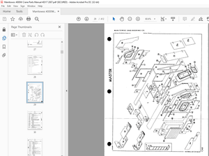
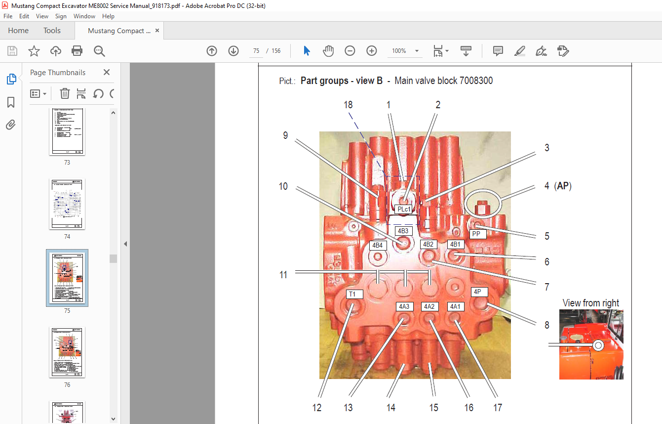
- Main Valve Block C22
- Second Valve Block C48
- Pilot Control Valves C51
- Swivel Unit C57
- Shuttle Valves (swivel motor brake) C64
- Drive Unit C65
- Swivel Joint C68
- Switch Valve C69
- Load Lowering Valve C70
- Hydraulic Oil Tank C71
D Diesel Engine:
- Diesel Engine Specifications D2
E Electrical:
- Electrical Wiring Diagram (up to serial number AB00473) E2
- Relay Position E6
- Solenoid Stop E7
- Glow Control Lamp Relay Plug E8
- Fuse Box E9
- Electrical Wiring Diagram (from serial number AB00473) E12
- Armrest Connections E14
F Operating Elements:
- Component Designation F2
- Joystick Consoles Component Designation F5
- Joystick Functions F7
- Auxiliary Hydraulics / Arm Swing F9
- Lifting the Excavator F10
- Torque Specifications
IMAGES PREVIEW OF THE MANUAL:
More products