$36
Mustang Compact Excavators 2803ZT Service Manual(918279) – PDF DOWNLOAD
Mustang Compact Excavators 2803ZT Service Manual(918279) – PDF DOWNLOAD
FILE DETAILS:
Mustang Compact Excavators 2803ZT Service Manual(918279) – PDF DOWNLOAD
Language : English
Pages : 154
Downloadable : Yes
File Type : PDF
Size: 10.1 MB
DESCRIPTION:
Mustang Compact Excavators 2803ZT Service Manual(918279) – PDF DOWNLOAD
Introduction
1.1 General Information
- Your decision to purchase the Mustang compact excavator was a good one. We are sure that your decision was carefully considered, and that you are looking forward to many years of reliable performance from the machine.
- Mustang Manufacturing Co., Inc. has invested much time and effort in developing its lines of equipment. The machine you have purchased is built with a great deal of pride and designed to provide long life, efficient operation, durability, and dependability.
- Modern machinery has become more sophisticated, and with that in mind, Mustang Manufacturing Co., Inc. asks that you read and completely understand the contents of this manual and become familiar with the new machine before attempting to service it.
- This manual was developed specifically for the machine you have purchased. The information within is for your assistance in preparing, adjusting, maintaining, and servicing the machine. More importantly, this manual provides a service plan for safe and proper servicing of the machine. Refer to the Table of Contents for an outline (by chapters) of this manual. Use the Index, located at the back of this manual, for specific chapter and topic/page number references.
- If the machine was purchased “used,” or if the owner’s address has changed, please provide your Mustang dealer or Mustang Manufacturing Co., Inc. with the owner’s name and current address, along with the machine model and serial number. This will allow the registered owner information to be updated, so that the owner can be notified directly in case of an important product issue, such as a safety update program.
- “Right” and “left” are determined from the position of sitting in the operator’s seat, facing forward.
- Mustang Manufacturing Co., Inc. reserves the right to make changes or improvements in the design or construction of any part without incurring the obligation to install such changes on any unit previously delivered.
- Throughout this manual, information is provided that is introduced by the words “NOTE” or “IMPORTANT”. Be sure to read carefully and comply with the message or directive given. Following this information will improve your maintenance efficiency, help you to avoid costly breakdowns or unnecessary damage, and extend the machine’s life.
- Operational safety and readiness of the machine depend partially on maintenance and service. This is why regular maintenance and service work is absolutely necessary. Extensive maintenance and repair work must always be carried out by a qualified technician with appropriate training. Insist on using Mustang original service parts when carrying out maintenance and repair work. This ensures operational safety and readiness of the machine, and maintains its value.
- Our wide dealership network stands ready to provide any assistance required, including genuine Mustang service parts. All parts should be obtained from or ordered through your Mustang dealer. Give complete information about the part, as well as the model number and serial number of your machine. Record numbers in the spaces provided, as a handy record for quick reference.
TABLE OF CONTENTS:
Mustang Compact Excavators 2803ZT Service Manual(918279) – PDF DOWNLOAD
Introduction
General Information 1-1
Serial number locations, type decals and component numbers 1-2
Designated uses and exemption from liability 1-4
Abbreviations/symbols 1-4
Identification of warnings and dangers 1-5
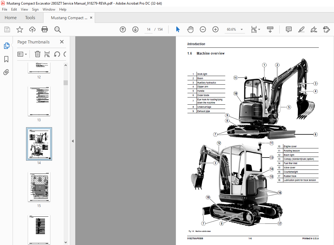
Machine overview 1-6
Cab overview 1-7
Cab legend 1-8
Instrument panel overview 1-9
Instrument panel legend 1-10
Engine compartment overview 1-11
Chassis overview 1-12
Valve compartment 1-13
Overview of open engine and valve compartment 1-14
Specifications
Chassis 2-1
Engine 2-1
Fuel injection pump 2-2
Engine capacities 2-2
Engine tightening torques 2-2
Hydraulic system 2-2
Work hydraulics 2-2
Auxiliary hydraulics oil flow 2-3
Undercarriage and swivel unit 2-3
Dozer blade 2-3
Electric system 2-3
Fuse box 2-4
Noise levels 2-5
Vibration 2-5
Coolant compound table 2-5
Model-specific tightening torques 2-6
General tightening torques 2-6
Tightening torques for hydraulic screw connections (dry assembly) 2-6
Tightening torques for high-resistance screw connections 2-8
Dimensions 2-9
Lift capacity table 2-10
Lift capacity table with optional counterweight 2-11
Bucket geometry 2-12
Maintenance
Fluids and lubricants 3-1
Additional oil change and filter replacement (hydraulics) 3-2
Maintenance label 3-3
Explanation of symbols on the maintenance label 3-3
Maintenance schedule 3-5
Check, clean or inspect 3-5
Fluid and filter changes 3-6
Functional check 3-6
Leakage check 3-6
Daily lubrication 3-7
Service package 3-8
Introduction 3-8
Fuel system 3-9
Specific safety instructions 3-9
Refueling 3-9
Stationary fuel pumps 3-10
Bleeding the fuel system 3-10
Emptying the fuel tank 3-11
Diesel fuel specification 3-11
Fuel shut-off valve and water separator 3-11
Replacing the fuel filter 3-12
Engine lubrication system 3-13
Checking the oil level 3-13
Adding engine oil 3-14
Changing engine oil and filter 3-15
Cooling system 3-16
Specific safety instructions 3-16
Checking/adding coolant 3-17
Draining coolant 3-18
Air filter 3-19
Replacing the filter 3-20
Functional check of the dust valve once a week 3-21
V-belt 3-22
Checking V-belt tension 3-22
Tightening the V-belt 3-23
Pressure checks 3-24
General 3-24
Pilot control pressure check 3-24
Variable-displacement pump P1 pressure check 3-25
Variable-displacement pump P2 pressure check 3-26
Gear pump P3 pressure check 3-27
Gear motor secondary pressure limiting valve pressure check 3-28
Test ports overview 3-28
Primary pressure limiting valves 3-29
Test report 3-31
Hydraulic system 3-33
Specific safety instructions 3-33
Checking the hydraulic oil level 3-34
Adding hydraulic oil 3-35
Changing hydraulic oil 3-35
Monitoring the hydraulic oil return filter 3-36
Checking hydraulic pressure lines 3-37
Travel drive 3-38
Checking the oil level and adding oil 3-38
Draining oil 3-38
Tracks 3-39
Checking track tension 3-39
Track tension 3-39
Lubrication 3-41
Dozer blade 3-41
Lubrication points on the swivel console 3-41
Boom lubrication points 3-42
Lubrication points on the dipper arm 3-42
Lubrication strip 3-43
Maintenance of attachments 3-43
Electrical system 3-44
Specific safety instructions 3-44
Regular service/maintenance 3-45
Specific component instructions 3-45
Alternator 3-45
Battery 3-46
Jump-starting the engine 3-47
Cab 3-48
Replacing the cab filter 3-48
General maintenance 3-49
Cleaning 3-49
General instructions for all areas 3-49
Inside the cab 3-50
Seat belt 3-50
Exterior of the machine 3-50
Engine compartment 3-50
Screw connections and attachments 3-50
Pivots and hinges 3-50
Engine
3TNV76-NNS engine overview 4-1
Fuel system 4-3
Checking and adjusting valve tip clearance 4-4
Tightening order for cylinder head bolts 4-4
Checking the injection nozzles 4-5
Pressure check 4-5
Checking the nozzle jet 4-5
Injection time 4-6
Checking and adjusting injection time 4-6
Fuel injection pump replacement 4-7
Adjusting engine rpm 4-8
Compression 4-8
Checking the coolant thermostat 4-8
Checking the thermal switch 4-9
Oil pressure switch 4-9
Checking the coolant circuit 4-10
Engine troubleshooting 4-10
Hydraulic system
Hydraulic pump PVD-0B-23BP-8G3-5083A 5-1
Pump unit: exploded view 5-3
Pilot oil supply unit 5-4
Main valve block 5-5
Ports 5-5
Legend 5-6
Main valve block diagram 5-7
Pressure limiting valves 5-8
Pump assignment 5-9
Drive counterbalancing system 5-10
Pump assignment for drive counterbalancing 5-10
Regeneration – dipper arm section 5-11
Bucket pre-tension 5-11
Flow rate adjustment of auxiliary hydraulics 5-12
Pilot valves 5-13
Joystick 5-13
Pilot valve (driving) 5-14
Pilot valve for auxiliary hydraulics 5-16
Changeover valve for SAE/ISO controls (option) 5-17
Proportional valve (option) 5-17
Travel drive 5-18
Function 5-19
Swivel unit 5-21
Swivel unit brake 5-22
Swivel joint 5-25
Sealing 5-25
Breather filter 5-26
Troubleshooting the hydraulic system 5-27
Hydraulics diagram: legend 5-28
Hydraulics diagram 5-29
Hydraulics diagram for options 5-30
Main valve block diagram 5-31
Electric system
Ohm’s Law (current, voltage, resistance); power 6-1
Measuring equipment, measuring methods 6-1
Cable color coding 6-3
Relays 6-3
Use, mode of function 6-3
Socket 6-3
Electric units 6-4
Fuse box 6-4
Switches: overview 6-5
Instrument panel legend 6-5
Alternator 6-6
Starter 6-6
Wiring diagram legend 6-7
Wiring diagram 6-8
Engine wiring harness legend 6-9
Engine wiring harness diagram 6-10
Cab wiring harness 6-11
Proportional controls (option) 6-12
Table of Contents
Printed in USA 1-5 918279/AP0508
Options
Counterweight 7-1
Specifications 7-1
Connecting auxiliary hydraulics 7-1
Attachments 7-2
Auxiliary hydraulics connections 7-2
Proportional controls 7-3
Function 7-3
Ports 7-4
Measures to be taken in case of malfunctions 7-4
Joystick 7-4
Boom swivel controls 7-5
Auxiliary hydraulics 7-5
Hammer operation 7-5
Adjusting control response 7-6
Characteristic curves – status display 7-6
Wiring harness 7-7
Control valve plug assignment 7-8
Safety features 7-9
Measures to be taken in case of malfunctions 7-9
Diagnostic display 7-9
IMAGES PREVIEW OF THE MANUAL:
More products