$35
Mustang Skid Steer Loader 2042 2044 2054 Service Manual(000-78025) – PDF DOWNLOAD
Mustang Skid Steer Loader 2042 2044 2054 Service Manual(000-78025) – PDF DOWNLOAD
FILE DETAILS:
Mustang Skid Steer Loader 2042 2044 2054 Service Manual(000-78025) – PDF DOWNLOAD
Language : English
Pages : 143
Downloadable : Yes
File Type : PDF
Size: 11.8 MB
DESCRIPTION:
Mustang Skid Steer Loader 2042 2044 2054 Service Manual(000-78025) – PDF DOWNLOAD
INTRODUCTION
- This manual was prepared to assist the experienced mechanic in troubleshooting and repair of MUSTANG loader Models 2042, 2044 and 2054. It contains information for proper service procedures and adjustments. For detailed information on the engine, hydrostatic pump, hydraulic pump, and drive motor repair, refer to the individual manufacturer’s service manual.
- When referred to, the left and right sides of the machine are determined as if sitting in the operator’s seat facing forward. All MUSTANG products are designed with operator safety as top priority. In some cases safety equipment must be removed for access to major components. Photos may show removal of safety equipment to complete repairs.
- Be sure to replace all safety equipment and be sure of proper operation when servicing is complete. Always provide the model and serial number when ordering parts or requesting service information.
- The serial number plate on older model units is located on the right rear upright, and, on newer units the serial number plate is located on the left rear upright [A]. MUSTANG MANUFACTURING COMPANY is continually striving to make improvements. We therefore reserve the right to make changes in product and/or specifications without notice and are under no obligation to make changes to previously manufactured equipment
General Precautions
- The safety alert symbol shown means: ATTENTION! BECOME ALERT! YOUR SAFETY IS INVOLVED! It stresses an attitude of “Heads Up for Safety” and can be found throughout this Service Manual and on the decals on the machine.
- Before operating or working on this machine, read and study the following safety information. In addition, be sure that everyone who operates or works with this equipment is familiar with these safety precautions. It is essential to have competent and careful operators, who are not physically or mentally impaired, and who are thoroughly trained in the safe operation of the machine and handling of loads. It is recommended that the operator be capable of obtaining a valid motor vehicle operator’s license.
- The use of skid steer loaders is subject to certain hazards that cannot be eliminated by mechanical means, but only by exercising intelligence, care and common sense. Such hazards include, but are not limited to, hillside operation, overloading, instability of the load, poor maintenance and using the equipment for a purpose for which it is not intended or designed.
- The Mustang Company ALWAYS considers the operator’s safety when designing its machinery and guards exposed moving parts for the operator’s protection. However, some areas cannot be guarded or shielded in order to assure proper operation. Furthermore, the Operator’s Manual and the decals on the machine warn of additional hazards and should be read and observed carefully.
- This section of the manual includes procedures, which when followed, will allow safe performance of service procedures: Mandatory Safety Shutdown Procedure, Lift arm Stops, Roll Over Protective Structure (ROPS)/Falling Object Protective Structure (FOPS), Safety Interlocks, Parking Brake, Lift Arm Bypass Switch, Loader Raising and Lowering Procedures.
TABLE OF CONTENTS:
Mustang Skid Steer Loader 2042 2044 2054 Service Manual(000-78025) – PDF DOWNLOAD
INTRODUCTION i
Serial Number System ii
SPECIFICATIONS
Specifications 2042 0-1
Specifications 2044 0-3
Specifications 2054 0-5
SAFETY
General Precautions 1-1
Safety Equipment 1-4
Lift Arm Stops 1-5
Roll Over Protective Structure – Removal and
Installation 1-6
Safety Interlocks 1-9
Lift Arm Bypass Switch 1-10
Parking Brake 1-11
Neutral Start Switches 1-16
Loader Lifting Procedure 1-17
GENERAL INFORMATION
System Contamination Control 2-1
Hydraulic Fluid 2-2
Maintenance Chart 2-3
Pre-delivery Check List 2-4
50 Hour Check List 2-5
Access Panels 2-6
Standard Torque Value Specifications 2-8
Metric Torque Value Specifications 2-9
Torque Specifications and Procedures
Hoses and Fittings 2-10
Special Tools 2-11
STEERING CONTROLS
General Information 3-1
Troubleshooting 3-2
Neutral Centering Device – Adjustments 3-4
Neutral Centering Device –
Service and Repair 3-5
Steering Controls – T-Bar 3-7
Steering Controls – Dual Lever 3-9
HYDRAULIC SYSTEM
General Information 4-1
Hi-Flow 4-2
Troubleshooting 4-4
Flow Diagram 4-7
Controls 4-9
Lift Circuit Leak-Down Test 4-11
Tilt Circuit Leak-Down Test 4-12
Hydraulic Cylinder Testing 4-13
Hydraulic Cylinder Service and Repair 4-14
Pressure and Flow Check 4-18
Gear Pump R & I 4-19
Control Valve 4-20
Self-Level Valve 4-22
HYDROSTATIC DRIVE SYSTEM
General Information5-1
Troubleshooting 5-2
Flow Diagram 5-3
Flow Schematic 5-5
System Checks
Charge Pressure 5-8
Power Check 5-10
Directional Check/Relief Valve 5-11
Hydrostatic Pump, Removal and Installation5-15
Drive Motor, Removal and Installation 5-17
CHAIN CASE
General Information – 2042/20446-1
Drive Chain – 2042/20446-2
Drive Axle and Sprocket – 2042/20446-3
General Information – 20546-5
Axle Housing R&I – 2054 6-6
Drive Chain & Sprocket R&I – 20546-10
Troubleshooting6-14
ENGINE
General Information7-1
Specifications 7-2
Troubleshooting 7-3
Engine / Hydrostatic Pump –
Removal and Installation 7-4
Cooling System 7-7
Troubleshooting 7-8
Fuel System7-9
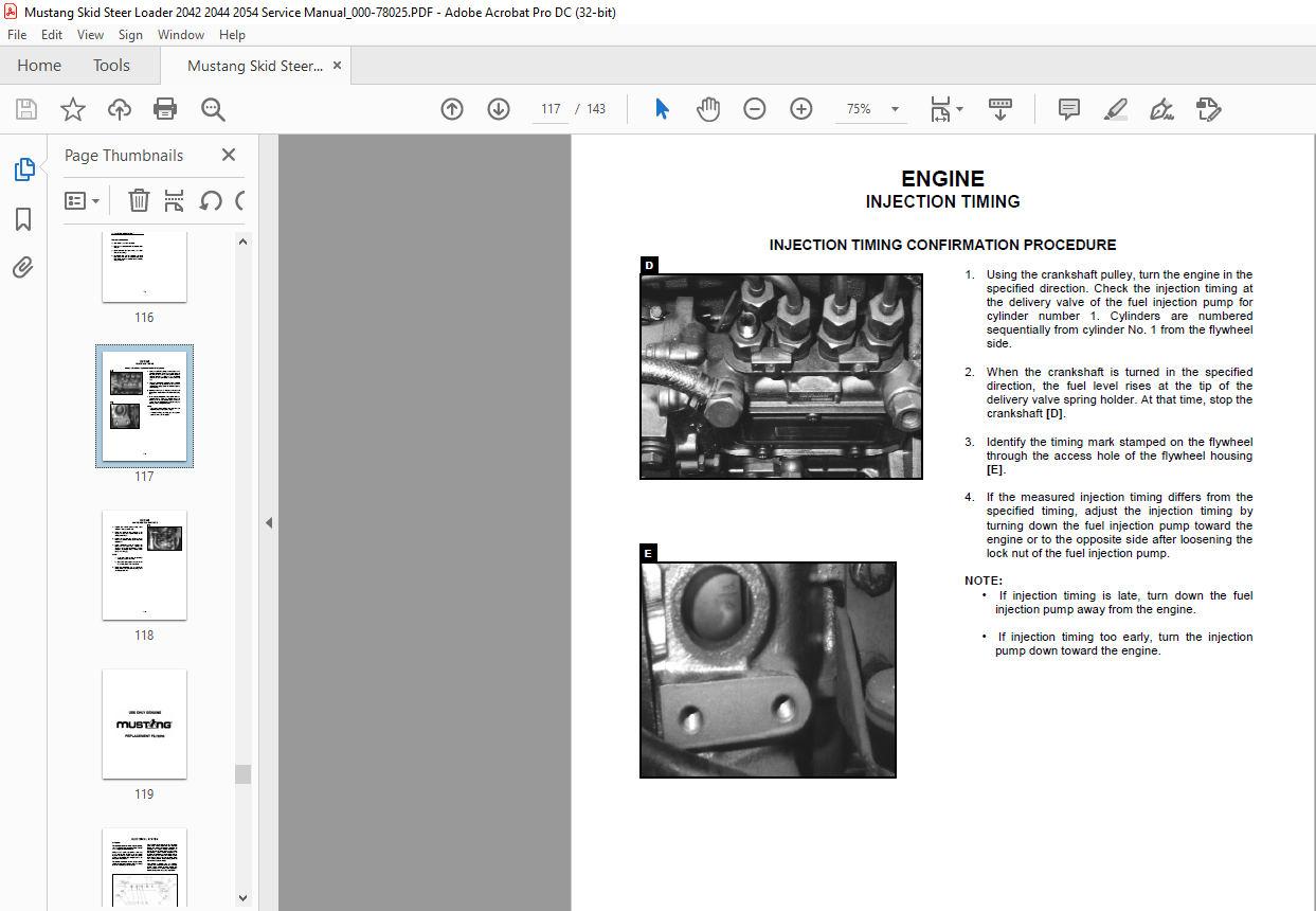
Injection Timing 7-10
Valve Clearance Adjustment 7-11
ELECTRICAL SYSTEM
General Information 8-1
Instrument Panel 8-2
Interlock Circuit 8-3
Interlock Circuit Wiring Diagram 8-4
Control Module Tests 8-5
Brake Circuit Wiring Diagram8-7
Troubleshooting8-8
Charging Circuit Diagram 8-14
Starter Circuit 8-15
Starter Circuit Wiring Diagram 8-17
Wiring Diagram Insert
Components 8-18
ACCESSORIES
Cab Door 9-1
Cabin Heater 9-1
Accessory Outlet / Int Light / Beacon9-2
Backup Alarm9-3
Auto Shutdown9-4
IMAGES PREVIEW OF THE MANUAL:
More products