$35
Mustang Skid Steer Loader 2066 2076 2086 Service Manual (917098) – PDF DOWNLOAD
Mustang Skid Steer Loader 2066 2076 2086 Service Manual (917098) – PDF DOWNLOAD
DESCRIPTION:
Mustang Skid Steer Loader 2066 2076 2086 Service Manual (917098) – PDF DOWNLOAD
INTRODUCTION
- With correct maintenance and proper use, Mustang skid-steer loaders will give years of dependable service. This service manual is intended to be a guide in the assembly and disassembly, installation and removal, adjustment and testing, troubleshooting and replacement of components that together make up the Mustang 2066/76/86 family of skid-steer loaders.
- In many of the procedures found within, the installation steps are the exact opposite of the removal steps and vice versa, and therefore, the opposite procedure is not written. Instead, a note to reverse the procedure will be stated. This reduces redundancy and excessive pages in the manual.
- In cases though, where the assembly and disassembly or removal and installation procedures differ and additional steps or safety concerns are paramount, the entire reverse procedure will be written out to include the new information. The Table of Contents and Index can be used to make the procedure you need to find an easier process.
- Also, there are black tabs extending off the pages highlighting the chapters for those who prefer to thumb through the manual. Many schematics, photographs, and lineart drawings are used to help perform the necessary repairs, tests or adjustments that the 2066/76/86 skid-steer loaders need to keep them in good running condition.
- If you have any additional questions, please contact your authorized Mustang dealer or call the Mustang Service Department for assistance.
IMAGES PREVIEW OF THE MANUAL:
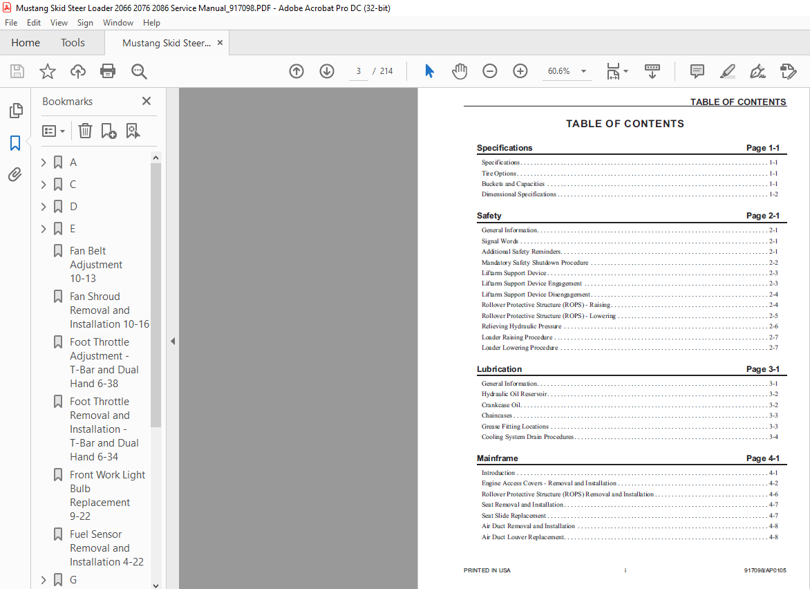
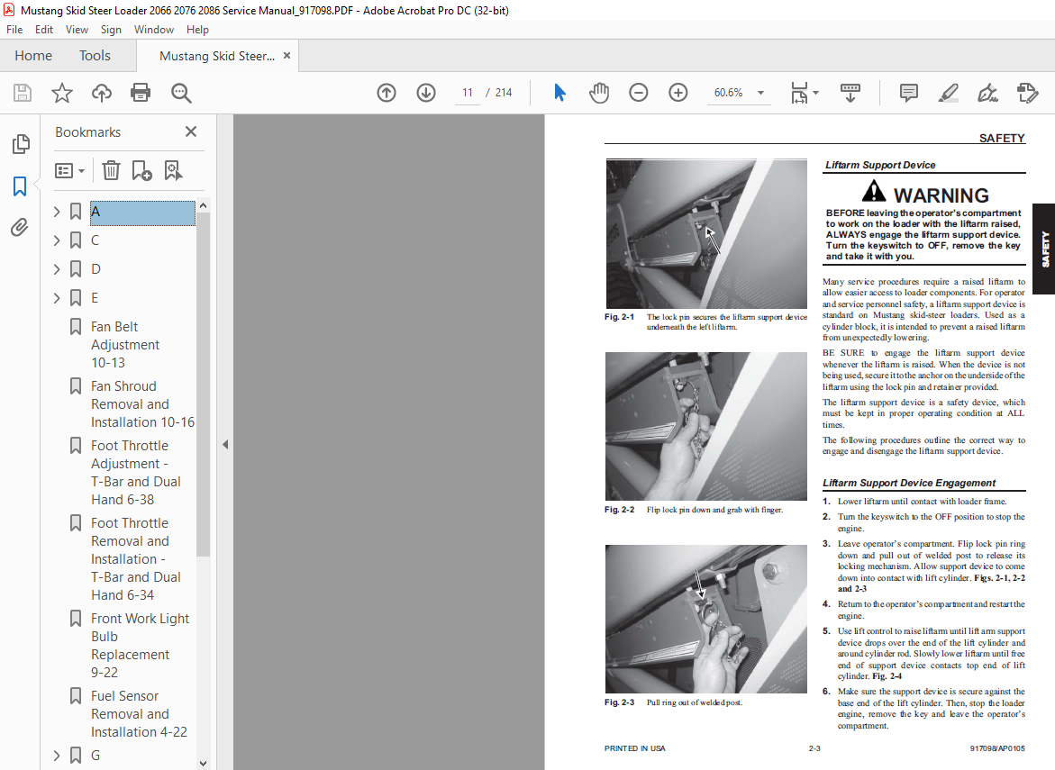
TABLE OF CONTENTS:
Mustang Skid Steer Loader 2066 2076 2086 Service Manual (917098) – PDF DOWNLOAD
Specifications Page 1-1
Specifications 1-1
Tire Options 1-1
Buckets and Capacities 1-1
Dimensional Specifications 1-2
Safety Page 2-1
General Information 2-1
Signal Words 2-1
Additional Safety Reminders 2-1
Mandatory Safety Shutdown Procedure 2-2
Liftarm Support Device 2-3
Liftarm Support Device Engagement 2-3
Liftarm Support Device Disengagement 2-4
Rollover Protective Structure (ROPS) – Raising 2-4
Rollover Protective Structure (ROPS) – Lowering 2-5
Relieving Hydraulic Pressure 2-6
Loader Raising Procedure 2-7
Loader Lowering Procedure 2-7
Lubrication Page 3-1
General Information 3-1
Hydraulic Oil Reservoir 3-2
Crankcase Oil 3-2
Chaincases 3-3
Grease Fitting Locations 3-3
Cooling System Drain Procedures 3-4
Mainframe Page 4-1
Introduction 4-1
Engine Access Covers – Removal and Installation 4-2
Rollover Protective Structure (ROPS) Removal and Installation 4-6
Seat Removal and Installation 4-7
Seat Slide Replacement 4-7
Air Duct Removal and Installation 4-8
Air Duct Louver Replacement 4-8
PRINTED IN USA i 917098/AP0105
TABLE OF CONTENTS
Rollover Protective Structure (ROPS) Rear Window Removal and Installation 4-9
Restraint Bar Removal and Installation 4-11
All-Tach™ Hitch Removal and Installation 4-14
Liftarm Removal and Installation 4-15
Liftarm and Cylinder Bushing Replacement 4-18
Liftarm Stop Installation and Adjustment 4-19
Control Cover, Floor Cover Removal and Installation 4-19
Crossmember Removal and Installation 4-20
Fuel Sensor Removal and Installation 4-22
Rear Grille Removal and Installation 4-23
Rear Grille Latch Removal and Installation 4-23
Wheel Drives Page 5-1
Introduction 5-1
Drive Chain Adjustment 5-2
Axle Housing Assembly Removal and Installation 5-3
Drive Chain Removal and Installation 5-4
Axle and Wheel Bearing Disassembly and Assembly 5-6
Controls Page 6-1
Introduction 6-1
Control Handle Removal and Installation 6-6
Control Handle Position Adjustment 6-7
Control Handle Tracking Adjustment, Drive Controls 6-8
T-Bar Control Handle Assembly 6-9
Hand/Foot Control Handle Assembly 6-11
Dual Hand Control Handle Assembly 6-12
Pivot Tube Removal and Installation – T-Bar, Hand/Foot and Dual Hand 6-16
Neutral Centering Device Adjustment 6-18
Control Arm Assembly Removal and Installation 6-19
Lift/Tilt Control Removal and Installation 6-20
Lift/Tilt Control Adjustment 6-23
Auxiliary Hydraulics Cable Removal and Installation – T-Bar and Dual Hand 6-27
Auxiliary Hydraulics Cable Adjustment – T-Bar and Dual Hand 6-28
Auxiliary Hydraulics Cable Removal and Installation – Hand/Foot 6-29
Auxiliary Hydraulics Cable Adjustment – Hand/Foot 6-30
Hand Throttle, Rod and Cable Removal and Installation – T-Bar and Dual Hand 6-33
Foot Throttle Removal and Installation – T-Bar and Dual Hand 6-34
Hand Throttle Tension Adjustment 6-35
917098/AP0105 ii PRINTED IN USA
TABLE OF CONTENTS
All-Tach and Hydraglide are trademarks of the Gehl Company
Hand Throttle and Throttle Cable Removal and Installation – Hand/Foot 6-36
Hand Throttle Adjustment – Hand/Foot 6-37
Foot Throttle Adjustment – T-Bar and Dual Hand 6-38
Hydrostatic System Page 7-1
Introduction 7-1
Troubleshooting Guide 7-3
Charge Pressure Test and Adjustment 7-7
Hydrostatic Pump Relief Valves 7-8
Hydrostatic Pump Removal and Installation 7-8
Hydrostatic Pump Drive Coupling Removal and Installation 7-10
Drive Motor Removal and Installation 7-11
Hydraulic System Page 8-1
Introduction 8-1
Troubleshooting Guide 8-1
Pressure Tests, Control Valve and High-Flow 8-13
Tilt Cylinder Test 8-15
Self-Leveling Valve Test 8-17
Lift Cylinder Test 8-18
Solenoid Valve Test – Tilt, Lift, Brake and Two-Speed 8-19
Hydraulic Oil Filter Element Replacement 8-21
Tilt Cylinder Removal and Installation 8-23
Lift Cylinder Removal and Installation 8-25
Lift and Tilt Cylinder Disassembly and Assembly 8-28
Gear Pump Removal and Installation 8-30
Self-Leveling Valve Removal and Installation 8-32
Self-Leveling Valve Adjustment 8-34
Safety Lock Valves – Removal and Installation 8-35
Lift and Tilt Solenoid Valves – Disassembly and Assembly 8-37
Control Valve Removal and Installation 8-38
High-Flow Manifold Valve Removal and Installation 8-42
High-Flow Manifold Valve Disassembly and Assembly 8-43
Pilot Valve Removal and Installation – Hand/Foot 8-44
Control Valve Disassembly and Assembly 8-46
Relief Valve Removal and Installation 8-46
Spool Lock Solenoid Removal and Installation 8-47
Hydraglide™ Accumulator Removal and Installation 8-49
Hydraulic/Hydrostatic System Schematic, 2066/76/86 Models 8-51
PRINTED IN USA iii 917098/AP0105
TABLE OF CONTENTS
Electrical System Page 9-1
Introduction 9-1
Description of Operation – Right and Left Instrument Panels 9-1
Troubleshooting Guide 9-3
Module and Relay Test and Operation 9-8
Seat Switch Removal and Installation 9-17
Restraint Bar Switch Removal and Installation 9-19
Engine Disconnect Switch – Remote Battery Terminal Removal and Installation 9-20
Front Work Light Bulb Replacement 9-22
Rear Work Light Bulb Replacement 9-22
Dome Light Bulb Replacement 9-23
Electrical System Schematic – ROPS/FOPS 9-24
Electrical System Schematic – Chassis 9-25
HVAC Schematic 9-26
Heater Schematic 9-27
Engine Page 10-1
Introduction 10-1
Troubleshooting Guide 10-1
Oil Filter Element Removal and Installation 10-7
Air Cleaner Assembly Removal and Installation 10-8
Air Filter Element Removal and Installation 10-9
Battery Removal and Installation 10-10
Starter Removal and Installation 10-11
Exhaust Assembly Removal and Installation 10-12
Fan Belt Adjustment 10-13
Cooler Radiator Removal and Installation 10-14
Fan Shroud Removal and Installation 10-16
Engine Removal and Installation 10-17
Index
More products