$36
Mustang Skid Steer Loader 2099 2107(EU) 2109 Service Manual (917036) – PDF DOWNLOAD
Mustang Skid Steer Loader 2099 2107(EU) 2109 Service Manual (917036) – PDF DOWNLOAD
DESCRIPTION:
Mustang Skid Steer Loader 2099 2107(EU) 2109 Service Manual (917036) – PDF DOWNLOAD
INTRODUCTION
With correct maintenance and proper use, Mustang skid-steer loaders will give years of dependable service. This
service manual is intended to be a guide in the assembly and disassembly, installation and removal, adjustment and
testing, troubleshooting and replacement of components that together make up the Mustang 2099, 2107 and 2109
skid-steer loaders.
IMPORTANT
For 2107 (EU) service information, follow procedures for 2099 skid-steer loaders, except where
noted separately.
- In many of the procedures found within, the installation steps are the exact opposite of the removal steps and vice versa, and therefore, the opposite procedure is not written. Instead, a note to reverse the procedure will be stated. This reduces redundancy and excessive pages in the manual.
- In cases though, where the assembly and disassembly or removal and installation procedures differ and additional steps or safety concerns are paramount, the entire reverse procedure will be written out to include the new information. The Table of Contents and Index can be used to make the procedure you need to find an easier process.
- Also, there are black tabs extending off the pages highlighting the chapters for those who prefer to thumb through the manual. Many schematics, photographs, and line art drawings are used to help perform the necessary repairs, tests, or adjustments that the Mustang skid-steer loader needs to keep it in good running condition.
- If you have any additional questions, please contact your authorized Mustang dealer or call the Mustang Service Department for assistance.
General Information
- The above safety alert symbol means: ATTENTION! BECOME ALERT! YOUR SAFETY IS INVOLVED! It stresses an attitude of “Heads Up for Safety” and can be found throughout this service manual and on the decals on the machine.
- Before operating or working on this machine, read and study the following safety information. In addition, be sure that every one who operates or works on this equipment is familiar with these safety precautions
- . It is essential to have competent and careful operators, who are not physically or mentally impaired, and who are thoroughly trained in the safe operation of the machine and the handling of loads.
- It is recommended that the operator be capable of obtaining a valid motor vehicle operator’s license. The use of skid steer loaders is subject to certain hazards that cannot be eliminated bymechanical means, but only by exercising intelligence, care and common sense.
- Such hazards include, but are not limited to, hillside operation, overloading, instability of the load, poor maintenance and using the equipment for a purpose for which it is not intended or designed. The Mustang Company ALWAYS considers the operator’s safety when designing its machinery and guards exposed moving parts for the operator’s protection. However, some areas cannot be guarded or shielded in order to assure proper operation.
- Furthermore, the Operator’s Manual and the decals on the machine warn of additional hazards and should be read and observed closely.
- This section of the manual includes procedures, which when followed, will allow safe performance of service procedures: Mandatory Safety Shutdown Procedure, Lift Cylinder Liftarm Support Device, Roll Over Protective Structure (ROPS)/Falling Object Protective Structure (FOPS) Lock Mechanism, Loader Raising and Lowering Procedures, and Relieving Hydraulic Pressure.
IMAGES PREVIEW OF THE MANUAL:
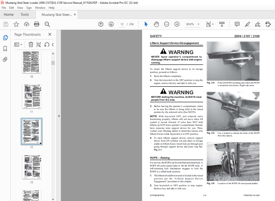
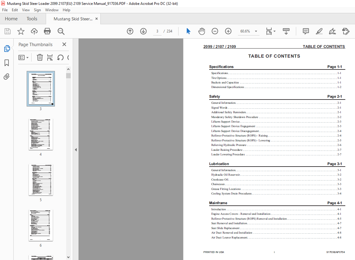
TABLE OF CONTENTS:
Mustang Skid Steer Loader 2099 2107(EU) 2109 Service Manual (917036) – PDF DOWNLOAD
Specifications Page 1-1
Specifications 1-1
Tire Options 1-1
Buckets and Capacities 1-1
Dimensional Specifications 1-2
Safety Page 2-1
General Information 2-1
Signal Words 2-1
Additional Safety Reminders 2-1
Mandatory Safety Shutdown Procedure 2-2
Liftarm Support Device 2-3
Liftarm Support Device Engagement 2-3
Liftarm Support Device Disengagement 2-4
Rollover Protective Structure (ROPS) – Raising 2-4
Rollover Protective Structure (ROPS) – Lowering 2-5
Relieving Hydraulic Pressure 2-6
Loader Raising Procedure 2-7
Loader Lowering Procedure 2-7
Lubrication Page 3-1
General Information 3-1
Hydraulic Oil Reservoir 3-2
Crankcase Oil 3-2
Chaincases 3-3
Grease Fitting Locations 3-3
Cooling System Drain Procedures 3-4
Mainframe Page 4-1
Introduction 4-1
Engine Access Covers – Removal and Installation 4-1
Rollover Protective Structure (ROPS) Removal and Installation 4-5
Seat Removal and Installation 4-7
Seat Slide Replacement 4-7
Air Duct Removal and Installation 4-8
Air Duct Louver Replacement 4-8
PRINTED IN USA i 917036/AP0704
2099 / 2107 / 2109 TABLE OF CONTENTS
Rollover Protective Structure (ROPS) Rear Window Removal and Installation 4-8
Restraint Bar Removal and Installation 4-9
All-Tach™, Power-A-Tach™ Hitch Removal and Installation 4-11
Liftarm Removal and Installation 4-15
Rear Link Removal and Installation 4-20
Timing Link Removal and Installation 4-22
Links and Liftarm Bushing Replacement 4-23
Control Console Removal and Installation 4-24
Floor Cover/Battery Cover Removal and Installation 4-25
Crossmember Removal and Installation 4-26
Fuel Sensor Removal and Installation 4-27
Rear Grille Removal and Installation 4-28
Rear Grille Bracket, Latch and Grille Removal and Installation 4-29
Rear Bumper Removal and Installation 4-30
Wheel Drives Page 5-1
Introduction 5-1
Drive Chain Adjustment 5-2
Axle Housing Assembly Removal and Installation 5-3
Drive Chain Removal and Installation 5-4
Axle and Wheel Bearing Disassembly and Assembly 5-6
Controls Page 6-1
Introduction 6-1
Control Handle Removal and Installation 6-6
Control Handle Position Adjustment 6-7
Control Handle Tracking Adjustment, Drive Controls 6-8
T-Bar Control Handle Assembly 6-9
Hand/Foot Control Handle Assembly 6-11
Dual Hand Control Handle Assembly 6-12
Pivot Tube Removal and Installation – T-Bar, Hand/Foot and Dual Hand 6-16
Neutral Centering Device Adjustment 6-18
Control Arm Assembly Removal and Installation 6-19
Lift/Tilt Control Removal and Installation 6-20
Lift/Tilt Control Adjustment 6-23
Auxiliary Hydraulics Cable Removal and Installation – T-Bar and Dual Hand 6-26
Auxiliary Hydraulics Cable Adjustment – T-Bar and Dual Hand 6-27
Auxiliary Hydraulics Cable Removal and Installation – Hand/Foot 6-28
Auxiliary Hydraulics Cable Adjustment – Hand/Foot 6-29
917036/AP0704 ii PRINTED IN USA
TABLE OF CONTENTS 2099 / 2107 / 2109
All-Tach is a trademark of the Gehl Company
Throttle Cable Removal and Installation 6-34
Throttle Sensor Removal and Installation 6-35
Hand Throttle Removal and Installation 6-35
Foot Throttle Removal and Installation – T-Bar and Dual Hand 6-36
Hand Throttle Tension Adjustment 6-37
Hand Throttle Adjustment – Hand/Foot 6-38
Foot Throttle Adjustment – T-Bar and Dual Hand 6-39
HIGH Idle Adjustment 6-40
Hydrostatic System Page 7-1
Introduction 7-1
Troubleshooting Guide 7-5
Charge Pressure Test and Adjustment 7-9
Hydrostatic Pump Relief Valves 7-10
Hydrostatic Pump Removal and Installation 7-10
Hydrostatic Pump Drive Coupling Removal and Installation 7-12
Drive Motor Removal and Installation 7-13
Hydraulic System Page 8-1
Introduction 8-1
Troubleshooting Guide 8-1
Pressure Tests, System and Load-Sense Standby 8-11
Tilt Cylinder Test 8-14
Self-Leveling Valve Test 8-15
Lift Cylinder Test 8-16
Solenoid Valve Test – Safety Lock, Brake and Two-Speed 8-18
Hydraulic Oil Filter Element Replacement 8-19
Tilt Cylinder Removal and Installation 8-21
Lift Cylinder Removal and Installation 8-23
Lift and Tilt Cylinder Disassembly and Assembly 8-26
Load-Sense Axial Piston Pump Removal and Installation 8-28
Self-Leveling Valve Removal and Installation 8-30
Self-Leveling Valve Adjustment 8-32
Safety Lock Valves – Removal and Installation 8-33
Lift, Tilt and Safety Lock Valves – Disassembly and Assembly 8-35
Control Valve Removal and Installation 8-36
Control Valve Disassembly and Assembly 8-40
Load-Sense Shuttle Cleaning Procedure 8-41
Control Valve Spool Seal Replacement 8-42
Anti-Cavitation Relief Valve Removal and Installation 8-43
Spool Lock Solenoid Removal and Installation 8-44
PRINTED IN USA iii 917036/AP0704
2099 / 2107 / 2109 TABLE OF CONTENTS
Hydraulic Tank Removal and Installation 8-45
Hydraglide™ Accumulator Removal and Installation 8-46
Hydraulic System Schematic 8-49
Engine Page 9-1
Introduction 9-1
Troubleshooting Guide 9-1
Oil Filter Element Removal and Installation 9-9
Air Cleaner Assembly Removal and Installation 9-10
Air Filter Element Removal and Installation 9-11
Battery Removal and Installation 9-12
Starter Removal and Installation 9-14
Exhaust Assembly Removal and Installation 9-15
Fan Belt Adjustment 9-16
Cooler Radiator Removal and Installation 9-17
Fan Shroud Removal and Installation 9-18
Fan Shroud Adjustment 9-19
Engine Removal and Installation 9-21
Fuel Tank Removal and Installation 9-24
Electrical System Page 10-1
Introduction 10-1
Description of Operation – Right and Left Instrument Panels 10-1
Troubleshooting Guide 10-4
Module and Relay Test and Operation 10-12
Seat Switch Removal and Installation 10-21
Restraint Bar Switch Removal and Installation 10-23
Engine Disconnect Switch – Remote Battery Terminal Removal and Installation 10-24
Front Work Light Bulb Replacement 10-26
Rear Work Light Bulb Replacement 10-26
Dome Light Bulb Replacement 10-27
Circuit Breaker and Fuse Replacement 10-28
Electric ROPS Lift Assist Pump Removal and Installation 10-29
Electrical System Schematics 10-33
Index
More products