$33
Mustang Skid Steer Loader 920 930A Service Manual (008-12909) – PDF DOWNLOAD
Mustang Skid Steer Loader 920 930A Service Manual (008-12909) – PDF DOWNLOAD
DESCRIPTION:
Mustang Skid Steer Loader 920 930A Service Manual (008-12909) – PDF DOWNLOAD
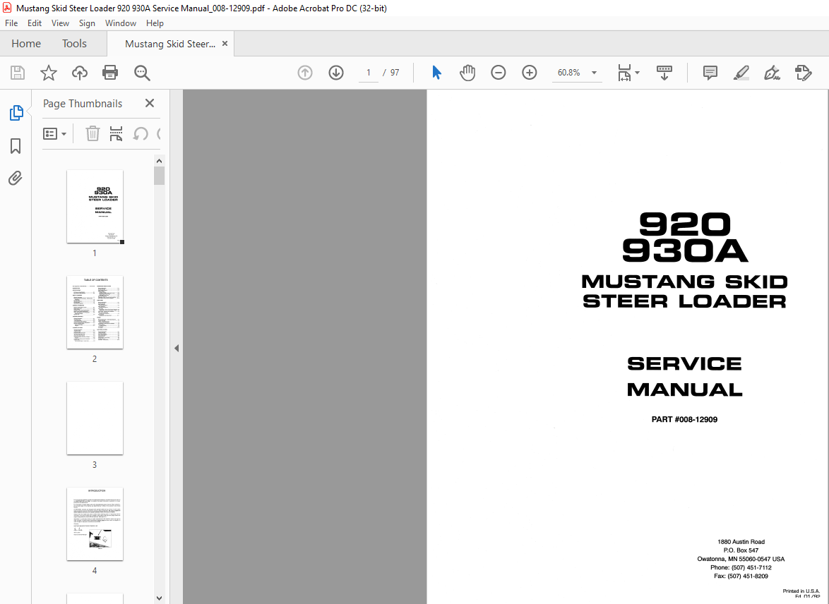
INTRODUCTION
- This manual was prepared to assist the experienced mechanic in troubleshooting and repair of the MUSTANG 920 and 930A. It contains the latest information available for proper procedures and adjustments. For information on engine repair, refer to the manufacturers service manual.
- When referred to, left and right sides of the machine are determined as if sitting in the operator’s seat facing forward. All MUSTANG products are designed with operator safety as top priority. In some cases safety equipment must be removed for access to major components.
- Be sure to replace all safety equipment and be sure of proper operation when servicing is complete. Always have the model and serial number when ordering parts or requesting service information.
- The serial number tag is located on the inside of the right rear upright, above the engine compartment lid, near the lift arm pivot pin. (See figure 0-1) MUSTANG is continually striving to make improvements. We therefore reserve the right to make changes in product and/or specifications without notice and are under no obligation to make changes to equipment manufactured previously.
TABLE OF CONTENTS:
Mustang Skid Steer Loader 920 930A Service Manual (008-12909) – PDF DOWNLOAD
New Equipment Limited Warranty ………… Front Cover
INTRODUCTION
SPECIFICATIONS
920 General Specifications …………………………. 0-1
930A General Specifications ………………………. 0-2
SAFETY EQUIPMENT
General Information …………………………………… 1-1
Roll Over Protective Structure – Removal and
Installation ……………………………………………. 1-2
Lift Arm Stops …………………………………………… 1-4
Seat Belt Lock-Out ……………………………………… 1-5
Parking Brake …………………………………………… 1-7
Neutral Start Switches ……………………………….. 1-8
GENERAL INFORMATION
System Contamination Control ……………………. 2-1
Maintenance Chart ……………………………………. 2-3
Access Panels ………………………………………….. 2-4
Standard Torque Value Specifications ………….. 2-6
Metric Torque Value Specifications ………………. 2-7
Torque Specifications and Procedures …………. 2-8
Hoses and Fittings
Special Tools ……………………………………………. 2-9
STEERING CONTROLS
General Information …………………………………… 3-1
Troubleshooting ………………………………………… 3-2
T-Bar Adjustments …………………………………….. 3-3
T-Bar Removal and Installation …………………… 3-4
Neutral Centering Device Adjustments …………. 3-5
Neutral Centering Device
Service and Repair ………………………………… 3-6
Diagram ……………………………………………….. 3-7
HYDRAULIC SYSTEM
General Information …………………………………… 4-1
Troubleshooting ………………………………………… 4-2
Pressure Check ………………………………………… 4-4
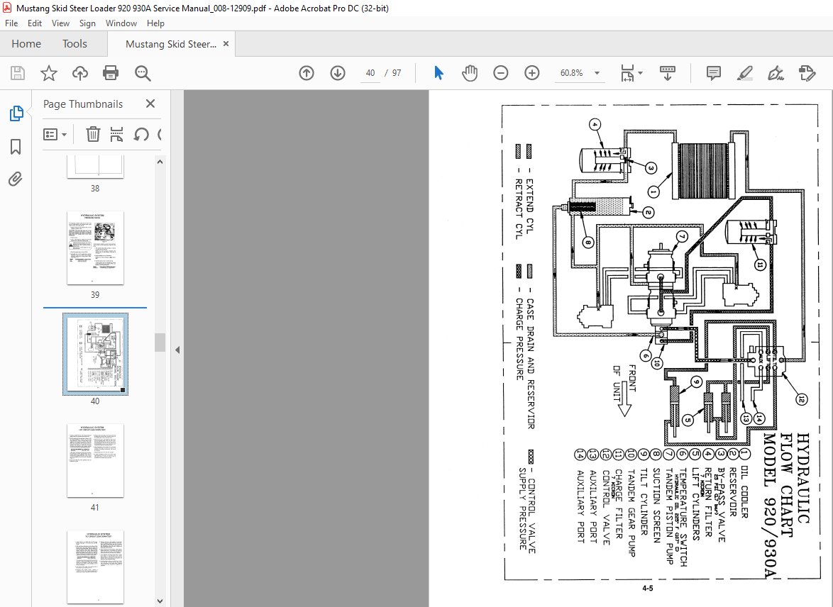
Model 920/930A Flow Chart ……………………….. 4-5
Lift Circuit Leak Down Test …………………………. 4-6
Tilt Circuit Leak Down Test …………………………. 4-7
Hydraulic Cylinder Testing ………………………….. 4-8
Hydraulic Cylinder Service and Repair …………. 4-9
Diagram ……………………………………………… 4-12
Control Valve Removal and Installation ………. 4-13
Control Valve
Service and Repair – Dukes Valve ………….. 4-14
HYDROSTATIC DRIVE SYSTEM
General Information …………………………………… 5-1
Trouble Shooting ………………………………………. 5-2
Drive System Diagram ……………………………….. 5-3
System Checks
Charge Pressure …………………………………… 5-4
Directional Check/ Relief Valve Comb. .. ……. 5-5
Closed Loop, Piston Pump ……………………… 5-6
Hydrostatic Drive Motor ………………………….. 5-7
Start Up Procedures ………………………………….. 5-9
Hydrostatic Pump, Removal and Installation .. 5-11
Drive Motor, Removal and Installation ………… 5-12
CHAIN CASE
General Information …………………………………… 6-1
Trouble Shooting ………………………………………. 6-2
Brake Assembly
Service and Repair I ………………………………. 6-3
Brake Assembly
Service and Repair II ……………………………… 6-5
Drive Chain
Adjustments / Chain Case Covers Removed 6-6
Adjustments / Chain Case Covers in Place .. 6-7
Drive Chain – Removal and Installation ………… 6-8
Drive Axle and Sprocket
Removal and Installation ………………………… 6-9
Idler Sprocket
Replacement and Adjustment ………………… 6-11
ENGINE
General Information – Model Specifications …… 7-1
Trouble Shooting ………………………………………. 7-2
Engine / Hydrostatic Pump
Removal and Installation ………………………… 7-3
Components – Removal and Installation ……….. 7-5
Cooling System ………………………………………… 7 -7
Trouble Shooting …………………………………… 7-8
Fuel System ……………………………………………… 7-9
Air Cleaner ……………………………………………… 7-10
ELECTRICAL SYSTEM
General Information …………………………………… 8-1
Trouble Shooting ………………………………………. 8-2
920 Wiring Diagram …………………………………… 8-4
930A Wiring Diagram ………………………………… 8-5
Instrument Panel ………………………………………. 8-6
Starting Circuit ………………………………………….. 8-7
Starter Motor – Disassembly ……………………….. 8-8
Charging Circuit ………………………………………… 8-9
Alternator – Disassembly ………………………….. 8-1 O
IMAGES PREVIEW OF THE MANUAL:
More products