$30
Mustang Wheel Loader ML28 Service Manual(918133)- PDF DOWNLOAD
Mustang Wheel Loader ML28 Service Manual(918133)- PDF DOWNLOAD
FILE DETAILS:
Mustang Wheel Loader ML28 Service Manual(918133)- PDF DOWNLOAD
Language : English
Pages : 172
Downloadable : Yes
File Type : PDF
Size: 2.50 MB
TABLE OF CONTENTS:
Mustang Wheel Loader ML28 Service Manual(918133)- PDF DOWNLOAD
Specifications
Type decals and component numbers ………………………………………………………………………………………………….TD-1
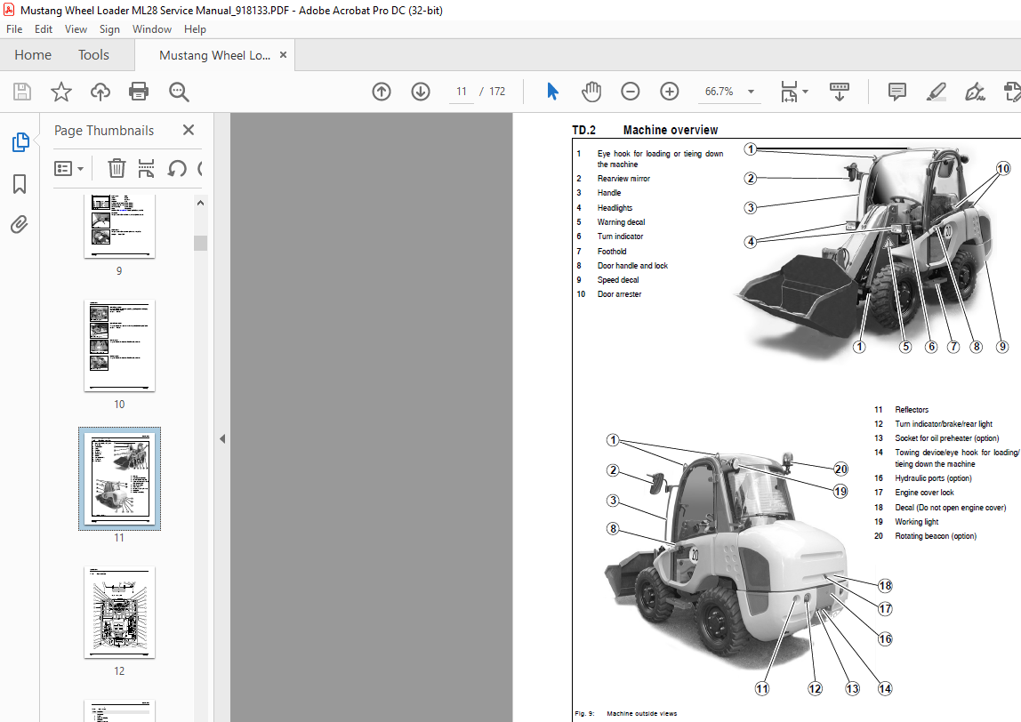
Machine overview ………………………………………………………………………………………………………………………………TD-3
Cab overview …………………………………………………………………………………………………………………………………….TD-4
Cab overview ………………………………………………………………………………………………………………………………..TD-5
Instrument panel, multifunctional lever and drive lever ……………………………………………………………………………TD-6
Instrument panel, multifunctional lever and drive lever: overview …………………………………………………………TD-7
Machine specifications ……………………………………………………………………………………………………………………….TD-8
Frame ………………………………………………………………………………………………………………………………………….TD-8
Engine …………………………………………………………………………………………………………………………………………TD-8
Power train …………………………………………………………………………………………………………………………………..TD-9
Axles ………………………………………………………………………………………………………………………………………….TD-10
Brakes ……………………………………………………………………………………………………………………………………….TD-10
Steering ……………………………………………………………………………………………………………………………………..TD-11
Work hydraulics …………………………………………………………………………………………………………………………..TD-11
Pilot control …………………………………………………………………………………………………………………………………TD-11
Additional control circuit + 4th control circuit (option) ………………………………………………………………………..TD-12
Loader unit …………………………………………………………………………………………………………………………………TD-12
Electrical system …………………………………………………………………………………………………………………………TD-13
Fuse box in control lever base ………………………………………………………………………………………………………TD-13
Main fuse box with relays in the engine compartment ………………………………………………………………………TD-13
Relays ……………………………………………………………………………………………………………………………………….TD-14
Tires ………………………………………………………………………………………………………………………………………….TD-15
Weights ……………………………………………………………………………………………………………………………………..TD-15
Sound levels ………………………………………………………………………………………………………………………………TD-15
Vibration ……………………………………………………………………………………………………………………………………TD-16
Coolant compound table ………………………………………………………………………………………………………………TD-16
General torques …………………………………………………………………………………………………………………………..TD-16
Specific torques ………………………………………………………………………………………………………………………….TD-16
Dimensions …………………………………………………………………………………………………………………………………TD-17
Maintenance
Fluids and lubricants …………………………………………………………………………………………………………………………..00-1
Explanation of symbols for the maintenance decal ………………………………………………………………………………….00-2
Maintenance decal …………………………………………………………………………………………………………………………00-3
Maintenance schedule (overview) …………………………………………………………………………………………………………00-4
Maintenance items ……………………………………………………………………………………………………………………………..00-7
Refueling …………………………………………………………………………………………………………………………………………..00-8
Stationary fuel pumps ……………………………………………………………………………………………………………………..00-8
Fuel prefilter (water separator) ……………………………………………………………………………………………………………..00-9
Cleaning the fuel filter ………………………………………………………………………………………………………………………..00-10
Bleeding the fuel system ……………………………………………………………………………………………………………………00-11
Engine lubrication system …………………………………………………………………………………………………………………..00-12
Checking the oil level ……………………………………………………………………………………………………………………00-12
Changing engine oil ………………………………………………………………………………………………………………………00-13
Changing the engine oil filter cartridge …………………………………………………………………………………………….00-14
Checking/filling up the coolant level …………………………………………………………………………………………………….00-15
Air filter ……………………………………………………………………………………………………………………………………………00-16
Replacing the filter cartridge …………………………………………………………………………………………………………..00-17
V-belt ………………………………………………………………………………………………………………………………………………00-18
918133/AP0405
Checking the V-belt tension …………………………………………………………………………………………………………..00-18
Tightening the V-belt …………………………………………………………………………………………………………………….00-18
Hydraulic system ………………………………………………………………………………………………………………………………00-19
Specific safety instructions …………………………………………………………………………………………………………….00-19
Checking the hydraulic oil level ………………………………………………………………………………………………………00-20
Adding hydraulic oil ………………………………………………………………………………………………………………………00-20
Changing hydraulic oil …………………………………………………………………………………………………………………..00-21
Use of biodegradable oil ………………………………………………………………………………………………………………..00-22
Replacing the hydraulic oil return filter …………………………………………………………………………………………….00-23
Replacing the filler and breather filter ………………………………………………………………………………………………00-23
Checking hydraulic pressure lines …………………………………………………………………………………………………..00-24
Gearboxes and axles …………………………………………………………………………………………………………………………00-25
Rear axle transfer gearbox …………………………………………………………………………………………………………….00-25
Front and rear axle differentials ………………………………………………………………………………………………………00-27
Lubricating the rear axle oscillation-type bearing ………………………………………………………………………………00-28
Front and rear axle planetary drives ………………………………………………………………………………………………..00-28
Loader unit ……………………………………………………………………………………………………………………………………….00-29
Lubricating the pivots on the loader unit …………………………………………………………………………………………..00-29
Tire care ………………………………………………………………………………………………………………………………………….00-30
Tire check ……………………………………………………………………………………………………………………………………00-31
Wheel change ……………………………………………………………………………………………………………………………..00-31
Electrical system ……………………………………………………………………………………………………………………………….00-32
Specific safety instructions …………………………………………………………………………………………………………….00-32
Service and maintenance work at regular intervals ……………………………………………………………………………00-32
Instructions concerning specific components ……………………………………………………………………………………00-33
Battery ………………………………………………………………………………………………………………………………………..00-34
General maintenance work …………………………………………………………………………………………………………………00-35
Cleaning ……………………………………………………………………………………………………………………………………..00-35
Screw connections ……………………………………………………………………………………………………………………….00-37
Pivots and hinges …………………………………………………………………………………………………………………………00-37
Engine
Specifications …………………………………………………………………………………………………………………………………….01-1
Description of engine type decal ……………………………………………………………………………………………………….01-2
Engine overview (front driving direction) ………………………………………………………………………………………………..01-3
Engine overview (rear driving direction) …………………………………………………………………………………………………01-4
Fuel injection system …………………………………………………………………………………………………………………………..01-5
Fuel injection nozzle ……………………………………………………………………………………………………………………………01-6
Engine valve tip clearance ……………………………………………………………………………………………………………………01-7
Engine cooling: overview ……………………………………………………………………………………………………………………..01-8
Fuel system: overview …………………………………………………………………………………………………………………………01-9
Engine trouble ………………………………………………………………………………………………………………………………….01-10
Power train
Description: Variable displacement pump A 10 VG 28 DA ………………………………………………………………………..22-1
Description: Hydraulic motor VM 45 EZ 6 ………………………………………………………………………………………………22-2
Fuel system: overview …………………………………………………………………………………………………………………………22-3
Measuring points: variable displacement pump ………………………………………………………………………………………22-4
Overview: hydraulic motor ……………………………………………………………………………………………………………………22-5
Diagram: hydraulic speed range ……………………………………………………………………………………………………………22-6
Table of contents
918133/AP0405
Check and adjustment instructions ………………………………………………………………………………………………………..22-7
Towing ………………………………………………………………………………………………………………………………………….22-7
Test report model …………………………………………………………………………………………………………………………..22-8
Adjusting boost pressure …………………………………………………………………………………………………………………22-9
Adjusting pilot pressure …………………………………………………………………………………………………………………22-10
Adjusting starting speeds ………………………………………………………………………………………………………………22-11
Adjusting the hydraulic resistance curve on the transposition screw ……………………………………………………22-12
Readjusting the hydraulic resistance curve ………………………………………………………………………………………22-13
Adjusting variable displacement pump output …………………………………………………………………………………..22-14
Adjusting high pressure/pressure cut-off ………………………………………………………………………………………….22-15
Pressure cut-off: exploded view ……………………………………………………………………………………………………..22-16
Adjusting control piston pressure of hydraulic motor ………………………………………………………………………….22-17
Axles
Type decal – axle ……………………………………………………………………………………………………………………………….23-1
Drain, fill and check plug ……………………………………………………………………………………………………………………..23-2
Tightening values lb-ft (Nm) …………………………………………………………………………………………………………………23-3
Screw connections ……………………………………………………………………………………………………………………………..23-4
Sealing work ………………………………………………………………………………………………………………………………………23-5
Differential – front axle ……………………………………………………………………………………………………………………23-5
Overview: Planetary carrier – double drive shaft …………………………………………………………………………………23-6
Sealing: Planetary carrier ………………………………………………………………………………………………………………..23-6
Overview: Planetary drive ……………………………………………………………………………………………………………..23-11
Sealing: Planetary drive ………………………………………………………………………………………………………………..23-11
Sealing: Axle carrier ……………………………………………………………………………………………………………………..23-13
Sealing: Axle carrier – differential ……………………………………………………………………………………………………23-15
Sealing: Gearbox – input flange ……………………………………………………………………………………………………..23-16
Overview: Self-locking differential ……………………………………………………………………………………………………….23-17
Brakes
Overview: Brake system ………………………………………………………………………………………………………………………24-1
Readjustment: Parking brake ……………………………………………………………………………………………………………….24-2
Replacing brake linings …………………………………………………………………………………………………………………..24-3
Basic setting: Cables …………………………………………………………………………………………………………………………..24-4
Cable for inching ……………………………………………………………………………………………………………………………24-4
Cable – parking brake …………………………………………………………………………………………………………………….24-5
Cable for parking brake …………………………………………………………………………………………………………………..24-6
Steering
Overview – steering circuit …………………………………………………………………………………………………………………..27-1
Steering diagram ………………………………………………………………………………………………………………………………..27-2
Hydraulic circuit: Steered to the left ……………………………………………………………………………………………………….27-3
Hydraulic circuit: Steered to the right ……………………………………………………………………………………………………..27-4
Hydraulic ports on servostat …………………………………………………………………………………………………………………27-5
Adjustment: Pressure relief valve – servostat …………………………………………………………………………………………27-5
Sealing steering cylinders …………………………………………………………………………………………………………………….27-6
Adjustment: Pressure relief valve – servostat …………………………………………………………………………………………27-5
Sealing steering cylinders …………………………………………………………………………………………………………………….27-6
918133/AP0405
Electrical system
Ohm’s Law (current, voltage, resistance); power …………………………………………………………………………………….33-1
Measuring equipment, measuring methods ……………………………………………………………………………………………33-1
Terminal description ……………………………………………………………………………………………………………………………33-3
Cable color coding ………………………………………………………………………………………………………………………………33-6
Relays ……………………………………………………………………………………………………………………………………………….33-7
Use, mode of function …………………………………………………………………………………………………………………….33-7
Terminal description on relay ………………………………………………………………………………………………………….33-7
Types of relays used ………………………………………………………………………………………………………………………33-8
Overview: Relays …………………………………………………………………………………………………………………………..33-8
Three-phase alternator, starter ……………………………………………………………………………………………………………..33-8
Battery ………………………………………………………………………………………………………………………………………………33-8
Fuse box in control lever base ………………………………………………………………………………………………………………33-9
Main fuse box with relays in the engine compartment ………………………………………………………………………………33-9
Overview: Board ……………………………………………………………………………………………………………………………….33-10
Plug and socket connection: Wiring harness 209336 frame – cab ……………………………………………………………33-11
Plug and socket connection: Wiring harness 209336 instrument panel …………………………………………………….33-12
Plug and socket connection: wiring harness 207414
– working light/rotating beacon ……………………………………………………………………………………………………………33-13
Wiring harness 207404 ………………………………………………………………………………………………………………………33-15
Cab – wiring harness 207412………………………………………………………………………………………………………………33-16
Roof – wiring harness 209336 ……………………………………………………………………………………………………………33-17
Roof – wiring harness 207414 ……………………………………………………………………………………………………………33-17
Wiring diagram 207406 ……………………………………………………………………………………………………………………..33-18
Cable colors: Steering-column control lever S2 and S3 to plugs 10.1, 10.2 and X9 ……………………………………33-21
Cable routing from steering-column control lever S3 on left, starting plug X9 …………………………………………….33-23
Cable routing from steering-column control lever S2 on right, starting plug 10.1 ………………………………………..33-24
Cable routing from steering-column control lever S2 on right, starting plug 10.2 ………………………………………..33-25
Hydraulics
Hydraulics diagram – pilot control …………………………………………………………………………………………………………36-1
Hydraulics diagram – float position ………………………………………………………………………………………………………..36-2
Hydraulic circuit: Pump – control valve – tank …………………………………………………………………………………………36-3
Overview: Control valve ……………………………………………………………………………………………………………………….36-4
Hydraulic ports on control valve ……………………………………………………………………………………………………………36-5
Hydraulic circuit pilot control …………………………………………………………………………………………………………………36-6
Sealing the lift cylinder …………………………………………………………………………………………………………………………36-7
Sealing the tilt cylinder …………………………………………………………………………………………………………………………36-8
Sealing the quickhitch cylinder ……………………………………………………………………………………………………………..36-9
Sealing: Quickhitch cylinder piston rod ……………………………………………………………………………………………36-10
Assembly tools …………………………………………………………………………………………………………………………….36-10
Overview: Loader unit ………………………………………………………………………………………………………………………..36-11
Hydraulic circuit 4th control circuit ……………………………………………………………………………………………………….36-12
Hydraulics diagram: 4th control circuit – solenoid valve no contact (neutral circulation) ………………………………36-13
Table of contents
918133/AP0405
Hydraulics diagram: 4th control circuit – solenoid valve with contact ………………………………………………………..36-14
Hydraulics diagram: 3rd + 4th control circuit – solenoid valve with contact ……………………………………………….36-15
Test and setting instructions for work hydraulics ……………………………………………………………………………………36-16
Test report …………………………………………………………………………………………………………………………………..36-16
Legend for hydraulics diagram ……………………………………………………………………………………………………………36-17
Hydraulics diagram ……………………………………………………………………………………………………………………….37-18
Heating
Heating circuit: overview ………………………………………………………………………………………………………………………41-IMAGES PREVIEW OF THE MANUAL:
More products