$33
Mustang Wheel Loader ML48T Service Manual(918139) – PDF DOWNLOAD
Mustang Wheel Loader ML48T Service Manual(918139) – PDF DOWNLOAD
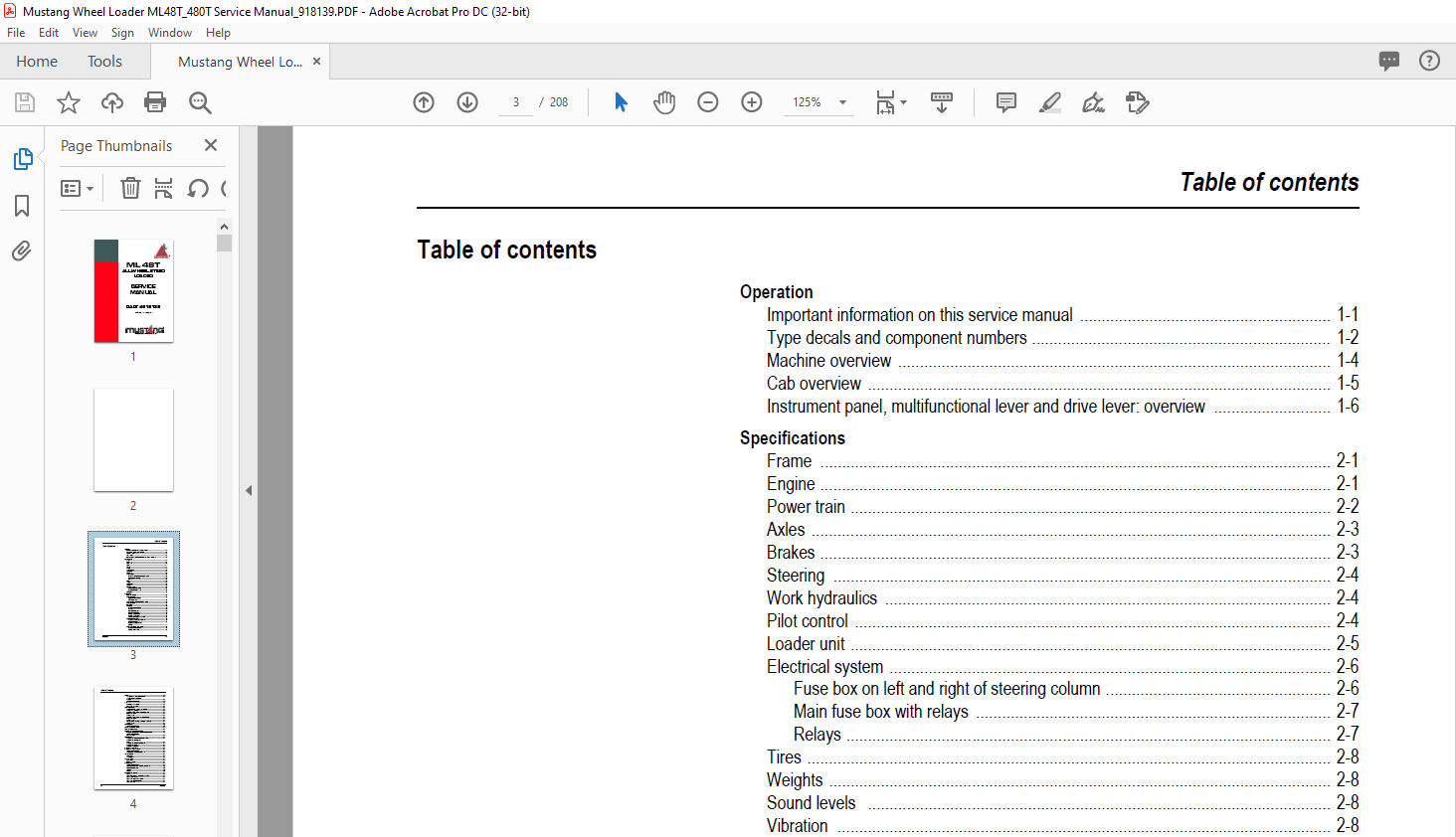
TABLE OF CONTENTS:
Mustang Wheel Loader ML48T Service Manual(918139) – PDF DOWNLOAD
Operation
Important information on this service manual …………………………………………………. 1-1
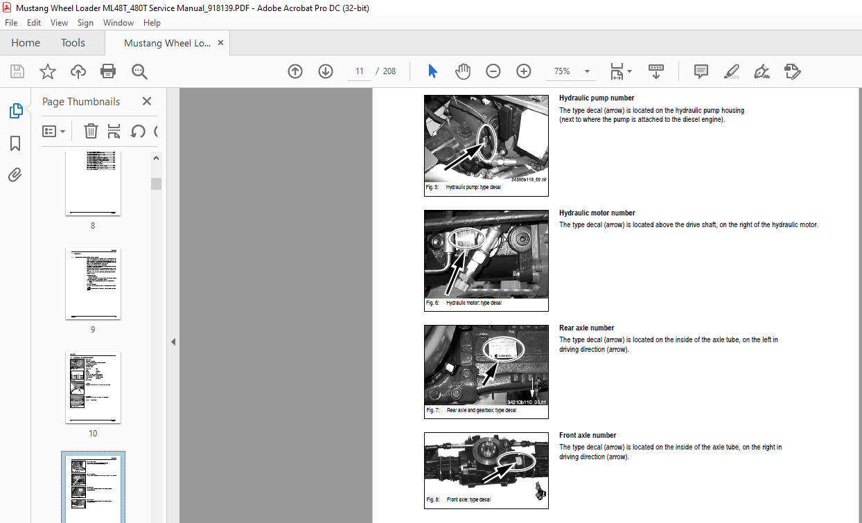
Type decals and component numbers …………………………………………………………… 1-2
Machine overview ………………………………………………………………………………………. 1-4
Cab overview …………………………………………………………………………………………….. 1-5
Instrument panel, multifunctional lever and drive lever: overview ……………………… 1-6
Specifications
Frame ………………………………………………………………………………………………………. 2-1
Engine ………………………………………………………………………………………………………. 2-1
Power train ………………………………………………………………………………………………… 2-2
Axles ………………………………………………………………………………………………………… 2-3
Brakes ………………………………………………………………………………………………………. 2-3
Steering ……………………………………………………………………………………………………. 2-4
Work hydraulics …………………………………………………………………………………………. 2-4
Pilot control ……………………………………………………………………………………………….. 2-4
Loader unit ………………………………………………………………………………………………… 2-5
Electrical system ………………………………………………………………………………………… 2-6
Fuse box on left and right of steering column ……………………………………………. 2-6
Main fuse box with relays ………………………………………………………………………. 2-7
Relays …………………………………………………………………………………………………. 2-7
Tires …………………………………………………………………………………………………………. 2-8
Weights …………………………………………………………………………………………………….. 2-8
Sound levels …………………………………………………………………………………………….. 2-8
Vibration …………………………………………………………………………………………………… 2-8
Tightening torques ……………………………………………………………………………………… 2-9
General tightening torques …………………………………………………………………….. 2-9
Specific tightening torques ……………………………………………………………………. 2-9
Dimensions ……………………………………………………………………………………………… 2-10
Maintenance
Fluids and lubricants ………………………………………………………………………………….. 3-1
Maintenance decal ……………………………………………………………………………………… 3-2
Explanation of symbols on
maintenance decal ……………………………………………………………………………….. 3-2
Maintenance schedule Model 480T (overview) ……………………………………………… 3-4
Maintenance items ……………………………………………………………………………………… 3-7
Introduction ……………………………………………………………………………………………….. 3-7
Fuel system ………………………………………………………………………………………………. 3-8
Specific safety instructions …………………………………………………………………….. 3-8
Refuelling …………………………………………………………………………………………….. 3-8
Stationary fuel pumps ……………………………………………………………………………. 3-8
Diesel fuel specification …………………………………………………………………………. 3-8
Bleeding the fuel system ……………………………………………………………………….. 3-9
Replacing the fuel filter ………………………………………………………………………….. 3-9
Cleaning the fuel pump screen filter ………………………………………………………… 3-9
Engine lubrication system ………………………………………………………………………….. 3-11
Checking and filling up the oil level ……………………………………………………….. 3-11
Changing engine oil …………………………………………………………………………….. 3-12
Replacing the engine oil filter
cartridge …………………………………………………………………………………………….. 3-13
Engine and hydraulic cooling system ………………………………………………………….. 3-14
Specific safety instructions …………………………………………………………………… 3-14
Cleaning the oil cooler …………………………………………………………………………. 3-14
Table of contents
I-2 918139/AP0905
Table of contents
Air filter ……………………………………………………………………………………………………. 3-15
Weekly check of air filter contamination …………………………………………………. 3-15
Weekly functional check of the
dust valve …………………………………………………………………………………………… 3-16
Replacing the filter cartridge …………………………………………………………………. 3-16
V-belt ………………………………………………………………………………………………………. 3-17
Checking the V-belt tension ………………………………………………………………….. 3-17
Re-tensioning the V-belt ………………………………………………………………………. 3-17
Gearboxes and axles ………………………………………………………………………………… 3-18
Checking and filling up the gearbox oil level ……………………………………………. 3-18
Changing the gearbox oil ……………………………………………………………………… 3-19
Checking the oil level in the rear axle differential …………………………………….. 3-20
Filling up the oil level …………………………………………………………………………… 3-20
Changing the oil ………………………………………………………………………………….. 3-20
Checking the oil level in the front axle differential …………………………………….. 3-21
Filling up the oil level …………………………………………………………………………… 3-21
Changing the oil ………………………………………………………………………………….. 3-21
Planetary drives: Checking and filling up the oil level ……………………………….. 3-22
Changing the oil ………………………………………………………………………………….. 3-22
Hydraulic system ………………………………………………………………………………………. 3-23
Specific safety instructions …………………………………………………………………… 3-23
Checking the hydraulic oil level …………………………………………………………………… 3-24
Filling up the hydraulic oil …………………………………………………………………………… 3-24
Monitoring the hydraulic oil return filter ………………………………………………………… 3-25
Important information for the use of biodegradable oil ……………………………… 3-25
Specific safety instructions
for pressure lines ………………………………………………………………………………… 3-26
Lubrication work ……………………………………………………………………………………….. 3-27
Lubricating the rear axle oscillation-type bearing …………………………………….. 3-27
Lubricating the planetary drive
bearing ………………………………………………………………………………………………. 3-27
Lubricating the pivots on the loader unit …………………………………………………. 3-28
Lubricating the loader unit ……………………………………………………………………. 3-28
Checking the wear pads ………………………………………………………………………. 3-28
Maintenance of attachments ………………………………………………………………………. 3-29
Maintenance of the brake system ……………………………………………………………….. 3-29
Specific safety instructions …………………………………………………………………… 3-29
Checking/filling up the brake fluid level …………………………………………………… 3-29
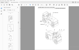
Tire maintenance ……………………………………………………………………………………… 3-30
Daily checks ……………………………………………………………………………………….. 3-30
Weekly checks ……………………………………………………………………………………. 3-30
Changing wheels …………………………………………………………………………………….. 3-31
Disassembly ………………………………………………………………………………………. 3-31
Fitting the wheels ………………………………………………………………………………… 3-31
Electrical system ………………………………………………………………………………………. 3-32
Specific safety instructions …………………………………………………………………… 3-32
Service and maintenance work at regular intervals ………………………………….. 3-33
Cables, bulbs and fuses ………………………………………………………………………. 3-33
Alternator …………………………………………………………………………………………… 3-33
Battery ………………………………………………………………………………………………. 3-33
General maintenance work ………………………………………………………………………… 3-34
Cleaning …………………………………………………………………………………………….. 3-34
General instructions for all areas of the machine …………………………………….. 3-34
Cleaning inside the cab ……………………………………………………………………….. 3-35
Cleaning the outside of the machine ……………………………………………………… 3-35
Cleaning the engine compartment …………………………………………………………. 3-35
Screw connections ………………………………………………………………………………. 3-35
918139/AP0905 I-3
Table of contents
Pivots and hinges ……………………………………………………………………………….. 3-36
Heating …………………………………………………………………………………………………… 3-36
Cleaning the dust filter of the heating system ………………………………………….. 3-36
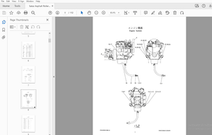
Engine
BF4M 2011/ F4M 2011 engine: overview ………………………………………………………. 4-1
Engine oil cooling ……………………………………………………………………………………….. 4-2
Fuel system ………………………………………………………………………………………………. 4-3
Engine level 2 (Tier II) …………………………………………………………………………………. 4-4
Checking and adjusting valve tip clearance ……………………………………………………. 4-5
Replacing the fuel injection pump …………………………………………………………………. 4-6
Turning off minus compensation …………………………………………………………… 4-11
Heating connection ……………………………………………………………………………… 4-11
Removing/mounting the cylinder head ………………………………………………………… 4-12
Sealing the bleeder valve …………………………………………………………………….. 4-15
Intake/exhaust manifold ……………………………………………………………………….. 4-15
Engine trouble …………………………………………………………………………………………. 4-15
Power train
Variable-displacement pump 12.5 mph (20 km/h) …………………………………………… 5-1
Hydraulic motor – hydraulic connections 12.5 mph (20 km/h) …………………………… 5-2
Hydraulic motor – control element 12.5 mph (20 km/h) ……………………………………. 5-3
Power train circuit with cooling 12.5 mph (20 km/h) ………………………………………… 5-4
Power train diagram 12.5 mph (20 km/h) ………………………………………………………. 5-5
Inching valve (left-hand side access) …………………………………………………………….. 5-6
Inching valve (component parts) …………………………………………………………………… 5-7
Test report 12.5 mph (20 km/h) ……………………………………………………………………. 5-8
Towing and transporting the machine ……………………………………………………………. 5-9
Safety instructions ………………………………………………………………………………… 5-9
Towing ………………………………………………………………………………………………… 5-9
Adjustment work on power train …………………………………………………………………. 5-10
Starting speeds …………………………………………………………………………………… 5-10
Adjusting boost pressure ……………………………………………………………………… 5-10
Adjusting pilot pressure ……………………………………………………………………….. 5-10
Hydraulic resistance (characteristic curve) of the pump…………………………….. 5-11
High pressure/drive pressure ……………………………………………………………….. 5-12
Secondary valves Fwd. – Rev. ……………………………………………………………… 5-13
Pump output/diesel output ……………………………………………………………………. 5-13
Control initiation on hydraulic motor ………………………………………………………. 5-14
Adjustment for wheel speed 12.5 mph (20 km/h) …………………………………….. 5-15
ECO speed 25 mph (40 km/h high speed) …………………………………………………… 5-16
Variable-displacement pump (40 km/h) ………………………………………………….. 5-16
Variable-displacement pump test ports ………………………………………………….. 5-17
ECO speed hydraulic motor …………………………………………………………………. 5-18
Positions of test port set screws ……………………………………………………………. 5-19
I-4 918139/AP0905
Table of contents
ECO speed power train 25 mph (40 km/h): diagram ……………………………………… 5-20
25 mph (40 km/h) test report ………………………………………………………………………. 5-21
Control initiation M3: settings ……………………………………………………………………… 5-22
Control initiation M4: settings ……………………………………………………………………… 5-23
Wheel speed: settings ……………………………………………………………………………….. 5-24
Axles
Type decal – axle ……………………………………………………………………………………….. 6-1
Front axle screw connections ………………………………………………………………………. 6-2
Rear axle screw connections ……………………………………………………………………….. 6-3
Drain, fill and check plug – front axle …………………………………………………………….. 6-4
Drain, fill and check plug – rear axle ……………………………………………………………… 6-5
Tightening torques lb.-ft. (Nm) – front axle …………………………………………………….. 6-6
Tightening torques lb.-ft. (Nm) – rear axle ……………………………………………………… 6-7
Sealing work ……………………………………………………………………………………………… 6-8
Input flange – front axle: sealing work ……………………………………………………… 6-8
Input flange – rear axle: sealing work ………………………………………………………. 6-9
Brake cylinder – front axle ……………………………………………………………………. 6-10
Planetary carrier – planetary drive: sealing work ……………………………………… 6-13
Planetary carrier – axle tube: sealing work ……………………………………………… 6-16
Sealing ring in axle tube: sealing work …………………………………………………… 6-18
Gearbox 12.5 mph (20 km/h):
sealing work ……………………………………………………………………………………….. 6-21
Differential lock ………………………………………………………………………………………… 6-22
Self-locking differential …………………………………………………………………………. 6-22
Differential cage with lock …………………………………………………………………….. 6-23
Brakes
Brake circuit ………………………………………………………………………………………………. 7-1
Brake diagram ……………………………………………………………………………………… 7-2
Bleeding the service brake …………………………………………………………………………… 7-3
Important information on the brake system ………………………………………………. 7-3
Bleeding the brake system with bleed equipment ……………………………………… 7-3
Parking brake: overview ………………………………………………………………………………. 7-4
Steering
12.5 mph (20 km/h) steering circuit ……………………………………………………………….. 8-1
12.5 mph (20 km/h) steering diagram ……………………………………………………………. 8-2
25 mph (40 km/h) steering circuit ………………………………………………………………….. 8-3
25 mph (40 km/h) steering diagram ………………………………………………………………. 8-4
Hydraulic connections on servostat ………………………………………………………………. 8-5
Pressure relief valve – servostat: settings ……………………………………………………… 8-5
Sealing the steering cylinder 12.5 mph/25 mph (20 km/h/40 km/h) ……………………. 8-6
Adjusting the steering sensors 25 mph (40 km/h) ……………………………………………. 8-7
Hydraulic system
Test report …………………………………………………………………………………………………. 9-1
Control valve connections ……………………………………………………………………………. 9-2
Priority valve for work hydraulics and steering ………………………………………….. 9-2
Control valve (position) ………………………………………………………………………….. 9-3
918139/AP0905 I-5
Table of contents
Work hydraulics circuit ………………………………………………………………………………… 9-4
Connections: frame – loader unit disconnect ………………………………………………….. 9-5
Loader unit hose routing ……………………………………………………………………………… 9-6
Pilot control unit: design ………………………………………………………………………………. 9-7
Pilot control circuit ………………………………………………………………………………………. 9-8
Valve positions …………………………………………………………………………………………… 9-9
Valve block for 3rd control circuit ………………………………………………………………… 9-10
Hose burst valve with load stabilizer: connections ………………………………………… 9-11
Load stabilizer diagram ……………………………………………………………………………… 9-12
Load stabilizer with hose burst valve: diagram ……………………………………………… 9-13
Tilt and lift cylinder: sealing…………………………………………………………………………. 9-14
Compensating and push-out cylinder: sealing……………………………………………….. 9-15
Control cylinder (quickhitch frame): sealing…………………………………………………… 9-16
Work hydraulics diagram …………………………………………………………………………… 9-17
Electrical system
Ohm’s Law (current, voltage, resistance); power …………………………………………… 10-1
Measuring equipment, measuring methods ………………………………………………….. 10-1
Terminal description …………………………………………………………………………………. 10-3
Cable color coding ……………………………………………………………………………………. 10-6
Other color codes (identical to IEC 757, edition 1983) ……………………………… 10-7
Relays …………………………………………………………………………………………………….. 10-7
Use, mode of function ………………………………………………………………………….. 10-7
Terminal description on relay ………………………………………………………………. 10-7
Fuse box, relays: overview ………………………………………………………………………… 10-8
Fuse box on left and right of steering column ………………………………………….. 10-8
Main fuse box with relays …………………………………………………………………….. 10-9
Relays ……………………………………………………………………………………………….. 10-9
Setting the safe load indicator ………………………………………………………………….. 10-10
Description ……………………………………………………………………………………….. 10-10
Qualification ……………………………………………………………………………………… 10-10
Necessary tools ………………………………………………………………………………… 10-10
General safety instructions …………………………………………………………………. 10-10
Description ……………………………………………………………………………………….. 10-11
Overview ………………………………………………………………………………………….. 10-11
Calibration ……………………………………………………………………………………….. 10-12
Setting the 0% point ………………………………………………………………………….. 10-12
Setting the 100% point ………………………………………………………………………. 10-13
Calibration values …………………………………………………………………………….. 10-14
Adjusting signal volume ……………………………………………………………………… 10-15
Functional check ……………………………………………………………………………….. 10-15
Troubleshooting ………………………………………………………………………………… 10-16
Steering electronics ………………………………………………………………………………… 10-17
Instrument panel, fuse box, relays: overview ………………………………………………. 10-18
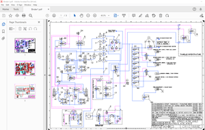
Wiring diagram: legend ……………………………………………………………………………. 10-20
Wiring diagram ……………………………………………………………………………………….. 10-21
Wiring harness 208587 engine – frame 12.5 mph (20 km/h): legend ……………… 10-22
Wiring harness: 208587 engine – frame 12.5 mph (20 km/h)…………………………. 10-23
Wiring harness 208689 engine – frame 25 mph (40 km/h): legend ……………….. 10-24
Wiring harness: 208689 engine – frame 25 mph (40 km/h) …………………………… 10-25
Wiring harness 208659 for cab: legend ……………………………………………………… 10-26
Wiring harness 208659 for cab ………………………………………………………………… 10-27
Wiring harness 208701 for cab (high speed) ………………………………………………. 10-28
Wiring harness 208700 for roof ………………………………………………………………… 10-29
Wiring harness for roof ……………………………………………………………………………. 10-30
I-6 918139/AP0905
Table of contents
Wiring harness 208562 on control lever base ……………………………………………… 10-31
Wiring harness 207409 for rear/clearance lights …………………………………………. 10-32
Wiring harness 1000103376 Telescopic …………………………………………………….. 10-33
Wiring harness 208111 for additional circuit (Optional) ………………………………… 10-34
Wiring harness 208609 (joystick) ………………………………………………………………. 10-35
Electronics between joystick and wiring harness 208609 ……………………………… 10-35
Wiring harness 208589 for load stabilizer ………………………………………………….. 10-36
Wiring harness 208676 for load stabilizer solenoid valve (option) …………………. 10-37
Wiring harness 207410 for control lever lock for long-haul travel ………………….. 10-38
Wiring harness 207407 for lock for long-haul travel, instrument panel …………… 10-39
Wiring harness 207411 for HighFlow additional hydraulics (option) ……………… 10-40
Wiring harness 207997 for front socket (option) ………………………………………… 10-41
Wiring harness 207999 for safe load sensor …………………………………………….. 10-42
Plug and socket connection: steering electronics –
steering-column control lever ……………………………………………………………………. 10-44
Plug and socket connection: fuse box and left-hand side relays ……………………. 10-45
Relay assignment (center) ……………………………………………………………………….. 10-46
Plug and socket connection: fuse box and right-hand side relays ………………….. 10-47
Plug and socket connection: cab ………………………………………………………………. 10-48
DESCRIPTION:
Mustang Wheel Loader ML48T Service Manual(918139) – PDF DOWNLOAD
1 Operation
1.1 Important information on this service manual
- This service manual contains important information on how to service your machine safely, correctly and economically. Therefore, it aims not only at new users, but also serves as a reference for experienced users. It helps to avoid hazardous situations and reduce repair costs and downtimes.
- Furthermore, the reliability and the service life of the machine will be increased by following the instructions in the Operator’s Manual. Careful and prudent work is the best way to avoid accidents! Operational safety and readiness of the machine do not only depend on your skill, but also on maintenance and service of the machine. Insist on using original authorized service parts when performing maintenance and repair work.
- This ensures operational safety and readiness of your machine, and maintains its value. Your authorized dealer will be pleased to answer any questions regarding the machine or this service manual.
IMAGES PREVIEW OF THE MANUAL:
More products