$45
New Holland 5610S, 6610S, 7010, 7610S, 7810S, 8010 Repair Manual - PDF DOWNLOAD
New Holland 5610S, 6610S, 7010, 7610S, 7810S, 8010 Repair Manual
FILE DETAILS:
New Holland 5610S, 6610S, 7010, 7610S, 7810S, 8010 Repair Manual
Size: 36.3 MB
Format: PDF
Language: English
Number of Pages: 706 pages
Brand: New Holland
Type of document: Repair Manual
Model: 5610S, 6610S, 7010, 7610S, 7810S, 8010
Part No: 87032901
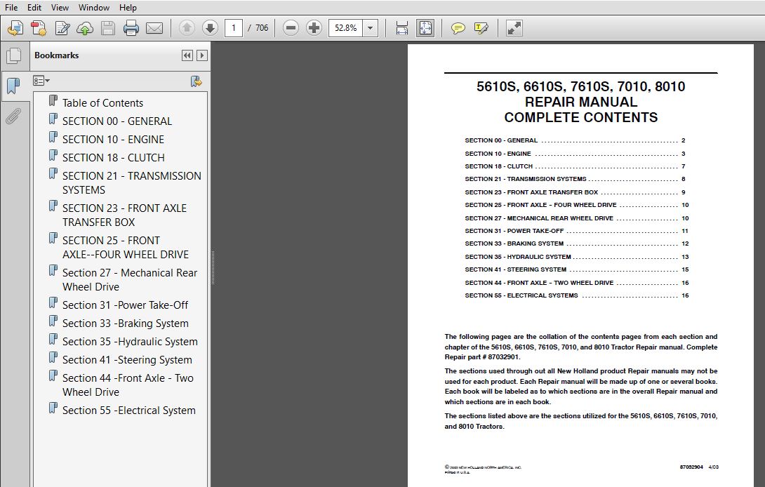
TABLE OF CONTENTS:
New Holland 5610S, 6610S, 7010, 7610S, 7810S, 8010 Repair Manual
SECTION 00 – GENERAL
BOOK 1 – 87032902
Chapter 1 — General
CONTENTS
Description Page
HEALTH AND SAFETY PRECAUTIONS 2
ACIDS AND ALKALIS 3
ADHESIVES AND SEALERS — see Fire 3
ANTIFREEZE — see Fire, Solvents eg Isopropanol, Ethylene Glycol, Methanol 3
ARC WELDING — see Welding 4
BATTERY ACIDS — see Acids and Alkalis4
BRAKE AND CLUTCH FLUIDS (Polyalkylene Glycols) — see Fire4
BRAZING — see Welding 4
CHEMICAL MATERIALS — GENERAL — see Legal Aspects 4
DOS4
DO NOTS5
CORROSION PROTECTION MATERIALS — see Solvents, Fire 5
DUSTS 5
ELECTRIC SHOCK5
EXHAUST FUMES6
FIBRE INSULATION — see Dusts 6
FIRE — see Welding, Foams, Legal Aspects 6
FIRST AID 6
FOAMS — Polyurethane — see Fire 6
FUELS — see Fire, Legal Aspects, Chemicals — General, Solvents 7
GAS CYLINDERS — see Fire 7
GENERAL WORKSHOP TOOLS AND EQUIPMENT 8
LEGAL ASPECTS 8
LUBRICANTS AND GREASES 8
PAINTS — see Solvents and Chemical Materials — General 9
SOLDER — see Welding 9
SOLVENTS — see Chemical Materials — General Fuels (Kerosene), Fire10
SUSPENDED LOADS10
WELDING — see Fire, Electric Shock, Gas Cylinders 10
3
SECTION 10 – ENGINE
BOOK 1 – 87032902
Chapter 1 – Diesel Engines
CONTENTS
Section Description Page
Specifications 2
Fault Finding 12
Description and Operation 17
Cylinder Head Assembly 17
Camshaft Assembly 17
Crankshaft Assembly 17
Connecting Rods 17
Pistons 17
Manifolds18
Cylinder Block Assembly 18
Timing Gears 18
Lubrication System19
Diesel Engine Strip-down 19
Separating the Tractor 21
Disassembly and Overhaul 26
Cylinder Head, Valves, and Related Parts26
Rocker Shaft 29
Cylinder Head29
Valve Inserts 32
Valve Guides 34
New Valve Guide Stem Seals 34
Valve Springs 36
Rocker Shaft 37
Cylinder Head38
Engine Front Cover and Timing Gear39
Oil Pan 43
Connecting Rods, Bearings, Pistons, and Rings 43
Connecting Rod Bushings 45
Cylinder Block47
Cylinder Bore 49
Sleeves 50
Balancer 58
Main Bearing 60
Flywheel 61
Rear Cover Plate 62
4
SECTION 10 – ENGINE
BOOK 1 – 87032902
Chapter 1 – Diesel Engines (Continued)
CONTENTS
Section Description Page
Oil Pump 64
Oil Filter Support Assembly 66
Crankshaft 68
Balancer Gear69
Timing Gear 70
Crankshaft 71
Camshaft73
Camshaft Bearings74
Overhaul 76
Intake Manifold 76
Exhaust Manifold 77
Testing 78
Engine Break-in (Low Hp Application)78
Engine Break-in (Other Than Low Hp Application) 79
SECTION 10 – ENGINE
BOOK 1 – 87032902
Chapter 2 – Engine Cooling System
CONTENTS
Section Description Page
Description and Operation2
Cooling System Overhaul3
Radiator 4
Thermostat 6
Water Pump7
5
SECTION 10 – ENGINE
BOOK 1 – 87032902
Chapter 3 – Air Cleaning System
CONTENTS
Section Description Page
Specifications 2
Torque Values 2
Fault Finding 2
Description and Operation2
Inner Element 6
SECTION 10 – ENGINE
BOOK 1 – 87032902
Chapter 4 – Fuel System
CONTENTS
Section Description Page
Specifications 2
Torque Values 2
Special Tools 2
Fault Finding 3
Diesel Engines 3
Fuel System6
Description and Operation6
Injectors 15
Fuel Injection Pump Adjustments 15
Idle Speed Adjustment 16
Maximum No-load Speed Adjustment17
DPS Fuel Injection Pump — Removal 18
DPS Fuel Injection Pump Timing (Non-Emissionized Engine)20
DPS Fuel Injection Pump — Installation 22
DP 200 Series Fuel Injection Pump 24
Special Tools 25
DP200 Series Fuel Injection Pump 28
6
SECTION 10 – ENGINE
BOOK 1 – 87032902
Chapter 4 – Fuel System (Continued)
CONTENTS
Section Description Page
DP200 Series Fuel Injection Pump Shaft Lock Timing 32
Alternative Method for Removing the DP200 Series Fuel
Injection Pump37
Alternative Method for Installing the DP200 Series Fuel
Injection Pump45
Fuel Injectors 47
Overhaul 47
Fuel Injector Testing 48
Inspection and Repair 51
Electric Lift Pump 54
Main Fuel Tank 55
Auxiliary Fuel Tank56
SECTION 10 – ENGINE
BOOK 1 – 87032902
Chapter 5 – Turbocharger
CONTENTS
Section Description Page
Specifications 2
Turbocharger 3
Fault Finding 5
Overhaul 7
7
SECTION 18 – CLUTCH
BOOK 1 – 87032902
Chapter 1 – Single Clutches
CONTENTS
Section Description Page
Description and Operation2
Operation 4
Adjustments5
Overhaul 5
Single Clutch Setting Procedure 10
Inspection and Repair 13
Installation 14
SECTION 18 – CLUTCH
BOOK 1 – 87032902
Chapter 2 – Servicing Clutch Associated Parts
CONTENTS
Section Description Page
Specifications and Special Tools 2
Torque Values 2
Clutch Pedal Free-play (Travel) 2
Special Tools 3
Clutch Pilot Bearing 4
Clutch Release Bearing 5
Clutch Release Shaft Bushings6
Clutch Pedal Bushings 6
8
SECTION 21 – TRANSMISSION SYSTEMS
BOOK 1 – 87032902
Chapter 1 – 8 x 2 Transmission
CONTENTS
Section Description Page
Specifications, Tightening Torques and Special Tools 2
8×2 Non-synchromesh Transmission 2
Torque Values 2
Special Tools 3
Tractor Specifications4
Ground Speeds 4
Transmission – Description and Operation 8
Introduction to Transmission Overhaul 10
Gear Shift Levers and Covers – Overhaul 10
Start Inhibitor Switch 12
Transmission Front End – Overhaul 12
Inspection and Repair 18
SECTION 21 – TRANSMISSION SYSTEMS
BOOK 1 – 87032902
Chapter 2 – 16 x 4 Dual Command (Dual Power) Transmission
CONTENTS
Section Description Page
Specifications 2
Torque Values 2
Special Tools 2
Fault Finding 3
Dual Command Transmission – Description and Operation5
Disassembly 12
Planetary Gear Set Shimming Procedure 17
Pressure Testing 19
9
SECTION 21 – TRANSMISSION SYSTEMS
BOOK 1 – 87032902
Chapter 3 – Reduction Gearbox Assembly
CONTENTS
Section Description Page
Specifications, Tightening Torqes, and Special Tools 2
Specifications 2
Tightening Torques 2
Special Tools 2
Reduction Gearbox – Description and Operation 3
Reduction Gearbox Overhaul 5
SECTION 23 – FRONT AXLE TRANSFER BOX
BOOK 1 – 87032902
Chapter 1 – Front Axle Transfer Box
CONTENTS
Section Description Page
Specifications 2
Clearances and Tolerances 2
Shim Thickness Available2
Oil Capacity2
Special Tools 2
Torque Values 2
Description and Operation3
Overhaul 5
10
SECTION 25 – FRONT AXLE–FOUR WHEEL DRIVE
BOOK 1 – 87032902
Chapter 1 – Four Wheel Drive
CONTENTS
Section Description Page
Specifications 2
Clearances and Tolerances 2
Shim Thickness Available2
Oil Capacity3
Special Tools 3
Torque Values 3
Description and Operation4
Adjustment 6
Hub and Planetary Reduction Gear Assembly – Overhaul 7
Axle Shafts – Overhaul 15
Steering Swivel Pin Bearings – Overhaul 19
Steering Cylinder and Track Rods Overhaul 24
Front Axle Removal and Installation28
Differential Crown Wheel and Pinion Assembly Overhaul 31
Drive Shaft – Overhaul 44
SECTION 27 – MECHANICAL REAR WHEEL DRIVE
BOOK 2 – 87032903
Chapter 1 – Rear Axle
CONTENTS
Section Description Page
Specifications 2
Rear Axle Shaft Bearing Pre-load Spacers 2
Differential Bearing Pre-load Spacers 2
Clearances and Tolerances 2
Torque Values 3
Oil Capacity3
Special Tools 4
11
SECTION 27 – MECHANICAL REAR WHEEL DRIVE
BOOK 2 – 87032903
Chapter 1 – Rear Axle (Continued)
CONTENTS
Section Description Page
Maximum Permissible Rear Axle Loading with Ballast and Mounted Equipment 4
Fault Finding 5
Description and Operation6
Final Reduction Gear Assembly (Planetary Gear)8
Separating the Tractor Between the Front Transmission and the Rear Axle 9
Rear Axle Shaft Assembly Overhaul10
Planetary Gear Assembly and Axle Housing Overhaul14
Differential and Differential Lock Assembly Overhaul 17
Differential Lock Control Linkage Overhaul 20
Drive Pinion Assembly Overhaul 22
Adjustments 25
Rear Axle Assembly Final Reduction Drop Trumpet (Drop Box) — Component
Overhaul 30
SECTION 31 – POWER TAKE-OFF
BOOK 2 – 87032903
Chapter 1 – Power Take-Off Systems
CONTENTS
Section Description Page
Specifications 2
Clearances and Tolerances 2
Shim Thickness Available2
Torque Values 2
Special Tools 3
PTO — Fault Finding 4
Description and Operation6
Mechanically Operated PTO Clutch 7
PTO Clutch Oil Flow Disengaged 7
12
SECTION 31 – POWER TAKE-OFF
BOOK 2 – 87032903
Chapter 1 – Power Take-Off Systems (Continued)
CONTENTS
Section Description Page
PTO Clutch Oil Flow – Engaged 9
PTO Pressure Test 12
Pressure Regulating Valve Test 12
Cooling and Lubrication Circuit Relief Valve Test 13
PTO Clutch Overhaul 13
PTO Shafts and Gears Overhaul 19
Single Speed Shafts and Gears – Overhaul 19
Two-speed Shafts and Gears Overhaul 21
16×4 Dual Command (Power) Transmission 28
SECTION 33 – BRAKING SYSTEM
BOOK 2 – 87032903
Chapter 1 – Braking System
CONTENTS
Section Description Page
Specifications 2
Special Tools 2
Fault Finding 2
Torque Values 2
Description and Operation3
Disc Brake Assembly Overhaul 5
Parking Brake Assembly Overhaul 6
Brake Pedal and Linkage Overhaul 7
13
SECTION 35 – HYDRAULIC SYSTEM
BOOK 2 – 87032903
Chapter 1 – Hydraulic Circuits
CONTENTS
Section Description Page
Specifications 2
Special Tools 4
Clearances and Tolerances 5
Torque Values 6
Fault Finding 7
Description and Operation9
Hydraulic Component — General Description 33
SECTION 35 – HYDRAULIC SYSTEM
BOOK 2 – 87032903
Chapter 2 – Hydraulic Pumps
CONTENTS
Section Description Page
Fixed Displacement Transmission Mounted (Tandem Gear) Type Pump 2
Description and Operation 2
Overhaul 4
Fixed Displacement Engine Mounted (Single Gear) Type Pump 11
Description and Operation 11
Overhaul 12
14
SECTION 35 – HYDRAULIC SYSTEM
BOOK 2 – 87032903
Chapter 3 – Remote Control Circuit
CONTENTS
Section Description Page
Description and Operation2
Remote Valve Circuit Oil Flow 3
Remote Control Valve — Overhaul 22
Remote Control Valve Coupler — Overhaul30
SECTION 35 – HYDRAULIC SYSTEM
BOOK 2 – 87032903
Chapter 4 – Component Overhaul
CONTENTS
Section Description Page
Oil Cooler — Overhaul2
Pressure Regulating Valve — Overhaul 2
Hydraulic Lift Cover — Overhaul 6
Priority Valve Pack — Overhaul 11
Hydraulic Lift Cylinder Assembly — Overhaul 14
SECTION 35 – HYDRAULIC SYSTEM
BOOK 2 – 87032903
Chapter 5 – Adjustments and Testing
CONTENTS
Section Description Page
Draft Control Main Spring Adjustment 2
Draft Control Linkage Adjustment 2
Position Control Linkage Adjustment 3
Remote Control Valve External Linkage Adjustment 4
Pressure Testing4
15
SECTION 41 – STEERING SYSTEM
BOOK 2 – 87032903
Chapter 1 – Hydrostatic Steering System
CONTENTS
Section Description Page
Specifications 2
Fault Finding 5
Description and Operation6
Oil Flow 10
SECTION 41 – STEERING SYSTEM
BOOK 2 – 87032903
Chapter 2 – Component Overhaul
CONTENTS
Section Description Page
Steering Motor 2
Steering Cylinder Two Wheel Drive 13
Steering Cylinder Four Wheel Drive19
Flow Control Valve — Power Steering Pump (Where Installed) 23
Transmission Mounted Tandem Pump24
Engine Mounted Power Steering Pump (Where Installed) 30
Steering System Testing 32
16
SECTION 44 – FRONT AXLE–TWO WHEEL DRIVE
BOOK 2 – 87032903
Chapter 1 – Two Wheel Drive
CONTENTS
Section Description Page
Specifications 2
Clearances and Tolerances 2
Front Axle Track Adjustment 2
Shim Thickness Available2
Special Tools 2
Torque Values 2
Description and Operation3
Adjustments4
Front Wheel Spindle – Overhaul 7
Center Steering Arm – Overhaul 10
Front Axle – Overhaul 11
SECTION 55 – ELECTRICAL SYSTEMS
BOOK 2 – 87032903
Chapter 1 – Description, Operation and Overhaul
CONTENTS
Section Description Page
Specifications — Starting System 3
Components4
Lamps 5
Torque Values 5
Fault Finding 6
Lighting and Instrumentation Systems 6
Starting System 7
Charging System7
Alternator 8
Electrical System 11
Precautionary Statements 11
17
SECTION 55 – ELECTRICAL SYSTEMS
BOOK 2 – 87032903
Chapter 1 – Description, Operation and Overhaul (Continued)
CONTENTS
Section Description Page
Description and Operation 11
Wire Harnesses 12
Electrical Components — Description, Operation and Overhaul 24
Instrument Panel 24
Instrument Panel Gauges 25
Instrument Panel Warning Lights26
Instrument Panel Overhaul 28
Four–Wheel Drive Select Switch32
Dual Power Switch34
Key–Start Ignition Switch 36
Lights Switch 38
Horn Switch 40
Warning Flasher Switch41
Power Take Off Switch 42
Neutral Start Switch 44
Cold Advance Thermostatic Switch 45
Air Cleaner Restriction Switch 45
Fuel/Water Separator Warning Switch47
Work Lamp Switch47
Oil Pressure Sender Switch 49
Stop Lamp Switch 50
Turn Signal Switch50
Main Fuel Tank Sender51
Auxiliary Fuel Tank Sender 51
Instrument Panel Lights52
Headlamps 53
Fender Mounted Headlamp 53
External Headlamp Bulb 53
Tail/Warning Lamp54
Work Lamp Bulb 56
Grille Mounted Headlamps 57
18
SECTION 55 – ELECTRICAL SYSTEMS
BOOK 2 – 87032903
Chapter 2 – Alternator and Charging System
CONTENTS
Section Description Page
Description and Operation2
Alternator — Overhaul4
Alternator — Testing 8
Alternator — Component Testing 15
SECTION 55 – ELECTRICAL SYSTEMS
BOOK 2 – 87032903
Chapter 3 – Starting Motor and System
CONTENTS
Section Description Page
Description and Operation2
Starting System Testing 2
Starting System Circuit Resistance Test3
Starting Motor — Overhaul4
SECTION 55 – ELECTRICAL SYSTEMS
BOOK 2 – 87032903
Chapter 4 – Battery, Servicing and Testing
CONTENTS
Section Description Page
Description and Operation2
Battery — Overhaul 3
Inspection and Servicing 4
Installation 5
19
SECTION 55 – ELECTRICAL SYSTEMS
BOOK 2 – 87032903
Chapter 5 – Electrical System Diagrams
CONTENTS
Section Description Page
Legend 1 — Non-Emissionized Engine 2
Table 1 — Non-Emissionized Engine3
Legend 2 — Emissionized Engine Less Fuel/Water Separator Circuit3
Table 2 — Emissionized Engine Less Fuel/Water Separator Circuit 4
Legend 3 — Emissionized Engine 5
Table 3 — Emissionized Engine6
Table 4 — Electrical Diagram Symbols 7
VIDEO PREVIEW OF THE MANUAL:
IMAGES PREVIEW OF THE MANUAL:
More products