$45
New Holland MC22 MC28 MC35 Commercial Mower Repair Manual 87557971 - PDF DOWNLOAD
New Holland MC22 MC28 MC35 Commercial Mower Repair Manual
FILE DETAILS:
New Holland MC22 MC28 MC35 Commercial Mower Repair Manual
Size: 25.3 MB
Format: PDF
Language: English
Number of Pages: 896 pages
Brand: New Holland
Type of document: Repair Manual
Model: MC22 MC28 MC35
Part No: 87557971
DESCRIPTION:
New Holland MC22 MC28 MC35 Commercial Mower Repair Manual
GENERAL :
The MC22, MC28, and MC35 tractors have been built using metric hardware. NOTE: Be sure to use the hardware specified when using tapped holes, as trying to install ametric bolt in an inch thread, or an inch bolt in a metric thread, will damage the thread. Certain hardware must be tightened to specific torque specifications. If specific torque specifications are not noted, tighten the hardware to the standard torque chart specification listed in this manual.
- PLATING:Hardware used on New Holland mowers is plated with zinc chromate (gold color). Gold colored hardware has different torquing requirements from unplated or zinc plated (silver color) hardware because of the difference in the coefficient of friction of the plating material. The torque charts in this manual list the correct specifications for gold, silver, and unplated bolts.
- NUT TIGHTENING :Whenever possible, the nut should be tightened, not the head of the bolt. When tightening using the bolt head, the clamp load can be lost because some of the torque applied twists the bolt instead of tensioning (stretching) it. The tension on the bolt is what holds the joint together. Approximately 90% of the torque applied during assembly goes to overcoming friction between the parts. The other 10% is used to tension (stretch) the bolt. After assembly, the frictional forces disappear, which is the basis for the saying If it does not fail during assembly, it will not fail in service. The bolt may later fail due to other factors, but not from being overtightened.
- LOCKNUTS :Most locknuts are coated with a special lubricant that is dry to the touch. Any time a locknut is used, a lower than normal torque is required. Refer to the torque charts in this manual for specific values. JAM NUTS When using a jam nut to lock a regular nut, the jam nut should be installed first and tightened to one half the recommended torque, then held in place while installing a regular nut to the recommended torque.
- THREAD LUBRICATION:The addition of antiseize compound, Molykote, oil, graphite, or any other lubricant to a bolt decreases the friction between it and a nut. This makes it necessary to reduce the recommended torque to prevent overtensioning of the bolt. When using the torque charts in this manual, decrease the value by 20% whenever a lubricant is used.
TABLE OF CONTENTS:
New Holland MC22 MC28 MC35 Commercial Mower Repair Manual
SECTION 00 — GENERAL INFORMATION
BOOK 1 – 87557972
Chapter 1 — General Information
CONTENTS
Section Description Page
Introduction 2
Precautionary Statements 3
Personal Safety 3
Machine Safety 3
Technical Information — Hardware 4
General 4
Plating 4
Nut Tightening 4
Locknuts 4
Jam Nuts 4
Thread Lubrication 4
Safety Precautions 5
Commercial Mower 5
Servicing the Commercial Mower 5
Driving the Commercial Mower 6
Operating the Power Take Off (PTO) 6
Operating the Mower Deck 7
Diesel Fuel 8
Avoid High-pressure Fluids 8
Safety 9
Safety Decals 12
International Symbols 17
Specifications 18
Minimum Hardware Tightening Torques 25
Special Tools 27
Lubricants 28
Touch-up Paint 29
00 100 Pre-season and Predelivery Service 30
Check and Adjust as Required 30
Inoperative Service Checks 30
Safety Items Checks 30
Operative Service Checks 30
3
SECTION 10 — ENGINE AND FUEL SYSTEMS
BOOK 1 – 87557972
Chapter 1 — Engine Systems
CONTENTS
Section Description Page
Specifications 6
General Engine Specifications 6
Cylinder Block Specifications 6
Cylinder Head Specifications 7
Piston Specifications 7
Piston Wrist Pin Specifications 8
Piston Ring Specifications 8
Connecting Rod Specifications 9
Crankshaft Specifications 10
Camshaft Specifications 12
Valve Specifications 13
Pushrod Specifications 14
Rocker Arm Specifications 14
Lubrication System Specifications 14
Cooling System Specifications 15
Engine Bolt Torque Specifications 16
Engine Fuel System Bolt Torque Specifications 16
Metric Bolt Torque Specifications — All Models 17
Special Tools 18
Compression Test 19
Description of Operation — Engine 21
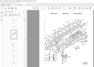
Cylinder Block 22
Cylinder Head And Valve Train Components 22
Troubleshooting 26
Overhaul — Engine 30
10 012 Engine 30
Removal 30
Fuel Injector and Glow Plug 35
Removal 35
Valve Cover/Air Intake — MC22 35
Removal 35
Air Intake Manifold Removal — MC28 and MC 35 35
Valve Cover — MC28 and MC35 36
Removal 36
4
SECTION 10 — ENGINE AND FUEL SYSTEMS
BOOK 1 – 87557972
Chapter 1 — Engine Systems (Continued)
CONTENTS
Section Description Page
Oil Transfer Tube 36
Removal 36
Water Pump Removal 36
Rocker Arm and Pushrod — MC22 37
Removal 37
Rocker Arm, Support Bracket, and Pushrod — MC28 and MC35 37
Removal 37
Exhaust Manifold 38
Removal 38
10 101 Engine Cylinder Head 38
Removal 38
Lifter (Valve Tappet) 39
Removal 39
Fuel Shutoff Solenoid 39
Removal 39
Timing Gear Cover 40
Removal 40
10 106 Timing Gears and Camshaft 41
Removal 41
10 102 Oil Pan and Pick-up 42
10 105 Removal 42
Connecting Rods, Bearings, and Piston 43
Removal 43
Backing Plate and Oil Seal 43
Removal 43
Front Crankshaft Gear 44
Removal 44
Crankshaft And Main Bearings 44
Removal 44
10 101 Cylinder Head 45
Disassembly 45
Inspection and Repair 45
Valve Seats 46
Inspection and Repair 46
Valves 47
Inspection and Repair 47
5
SECTION 10 — ENGINE AND FUEL SYSTEMS
BOOK 1 – 87557972
Chapter 1 — Engine Systems (Continued)
CONTENTS
Section Description Page
Valve Guides 48
Inspection and Replacement 48
Valve Springs 49
Inspection and Replacement 49
Rocker Arms — MC22 49
Inspection and Replacement 49
Rocker Arms — MC28 and MC35 50
Inspection and Replacement 50
Pushrods 51
Inspection and Replacement 51
Cylinder Head 51
Assembly 51
10 001 Cylinder Block 52
Inspection 52
10 105 Pistons 53
Disassembly and Inspection 53
Piston Rings 56
Inspection 56
Connecting Rods 57
Inspection 57
Connecting Rod Bearing Oil Clearance Check 59
Pistons, Rings, And Connecting Rod 60
Assembly 60
10 103 Main Bearing — MC22 61
Removal and Inspection 61
Main Bearing and Thrust Washer — MC28 and MC35 63
Removal and Inspection 63
Crankshaft — All Models 65
Inspection 65
Main Journal Number One Bearing (Bushing) 67
Inspection 67
Replacement 68
Crankshaft Front Gear, Main Bearings And Thrust Washers — MC28/MC35 68
Assembly 68
6
SECTION 10 — ENGINE AND FUEL SYSTEMS
BOOK 1 – 87557972
Chapter 1 — Engine Systems (Continued)
CONTENTS
Section Description Page
10 304 Oil Pump Port Block 69
Removal 69
Installation 70
Timing Gear 70
Inspection 70
Camshaft 71
Disassembly 71
Inspection 71
Assembly 72
10 103 Flywheel 73
Inspection And Repair 73
Timing Gear Housing 73
Front Oil Seal and Steering Pump Seal 73
Replacement 73
Crankshaft and Bearing Holder 74
Installation 74
Rear Oil Seal and Backing Plate 75
Installation 75
Piston and Connecting Rod 75
Installation 75
10 102 Oil Pick-up and Pan 76
Installation 76
Camshaft and Timing Gear 76
Installation 76
10 106 Oil Pump, Idler Gear, and Injection Timing 77
Installation 77
Timing Gear Cover 77
Installation 77
Crankshaft Pulley 77
Installation 77
Fuel Injection Pump 78
Installation 78
10 101 Head Gasket Selection 78
Cylinder Head 79
Assembly 79
7
SECTION 10 — ENGINE AND FUEL SYSTEMS
BOOK 1 – 87557972
Chapter 1 — Engine Systems (Continued)
CONTENTS
Section Description Page
Valve Clearance Adjustment 80
Exhaust Manifold 80
Installation 80
Oil Transfer Tube 81
Installation 81
Water Pump 81
Installation 81
Valve Cover/Air Intake — MC22 81
Installation 81
Air Intake Manifold — MC28 and MC 35 81
Installation 81
Valve Cover — MC28 and MC35 82
Installation 82
Fuel Injector and Glow Plug 82
Installation 82
Engine 82
Installation 82
Lubrication System Specifications 88
10 304 Description of Operation — Engine Lubrication System 89
10 306 Oil Filter 92
Construction and Function 92
Maintenance 92
Oil Pump 92
Removal 92
Inspection 92
Installation and Adjustment 93
Engine Oil Pressure Check 94
Oil Pressure Relief Valve 95
Removal 95
Installation 95
Oil Consumption 95
10 400 Description of Operation — Cooling System 96
Specifications 98
Maintenance 99
Coolant 99
8
SECTION 10 — ENGINE AND FUEL SYSTEMS
BOOK 1 – 87557972
Chapter 1 — Engine Systems (Continued)
CONTENTS
Section Description Page
Radiator Cap 99
10 402 Thermostat — MC22 100
Thermostat — MC28 and MC35 100
Water Pump 101
Cooling Fan 101
Overhaul — Cooling System 102
10 406 Radiator 102
Removal 102
Inspection 104
Installation 105
10 402 Water Pump — MC22 107
Removal 107
Water Pump — MC28 and MC35 109
Removal 109
Inspection 110
Water Pump — MC22 110
Installation — MC22 110
Water Pump — MC28 and MC35 111
Installation 111
10 402 Thermostat — MC22 113
Removal 113
Thermostat — MC28 and MC35 113
Removal 113
Inspection 114
Thermostat — MC22 114
Installation 114
Thermostat — MC28 and MC35 115
Installation 115
9
10
SECTION 10 — ENGINE AND FUEL SYSTEMS
BOOK 1 – 87557972
Chapter 2 — Fuel Systems
CONTENTS
Section Description Page
Specifications 3
Engine Fuel System Bolt Torque Specifications 3
Special Tools 3
10 242 Description of Operation — Injection Pump — MC22 4
Pumping Elements 6
Delivery Valves 8
Injection Pump — MC28 and MC35 — Description and Operation 10
10 242 Fuel Variation Mechanism 11
Delivery Valve Assembly 12
CTD (Compact Timing Device) Mechanism 12
Pumping Elements 15
Delivery Valves 17
Troubleshooting — General 19
Overhaul 20
Injection Pump 20
Removal 20
Repair 21
Installation 22
Spill-Timing and Governor Adjustments 23
New Injection Pump or Drive Component 23
Installation 23
Spill-Timing Procedure 24
Fuel System Bleeding 29
Automatic Bleeding 29
Fuel Flow Chart 29
Manual Bleeding 30
Smoke Screw and High Idle Adjustment 31
10 230 Description and Operation — Governor 31
Troubleshooting — Governor System 33
11
SECTION 10 — ENGINE AND FUEL SYSTEMS
BOOK 1 – 87557972
Chapter 2 — Fuel Systems (Continued)
CONTENTS
Section Description Page
10 230 Governor 36
Disassembly 36
Assembly 37
Governor Adjustments 39
10 218 Description and Operation — Fuel Injectors 40
Fuel Filter and Shutoff Valve 41
Troubleshooting — Fuel Injectors 42
10 218 Injectors 43
Removal 43
Disassembly 44
Assembly and Adjustment 44
Description of Operation — Engine Breather Valve 45
Engine Breather Valve 46
Removal 46
Installation 46
Troubleshooting — Engine Breather Valve 47
12
SECTION 25 — FOUR WHEEL DRIVE REAR AXLE
BOOK 2 – 87557973
Chapter 1 — Four Wheel Drive Rear Axle
CONTENTS
Section Description Page
Specifications 2
Rear to Front Axle Ration 3
Metric Bolt Torque Specifications 5
25 100 Description of Operation 6
25 104 Two-way (Sensitrack™) Clutch 9
Automatic Position – Clutch Engaged 10
Automatic Position – Clutch Disengaged 10
Fulltime FWD Position – Clutch Locked 10
Power Flow 11
Troubleshooting 12
Adjustment 13
Rear Wheel Toe-In 13
Overhaul 14
Rear Axle 14
Removal 14
Drop Box 15
Disassembly 15
Inspection 21
25 310 Assembly 21
Rear Axle and Differential 29
Disassembly 29
Inspection 34
25 102 Assembly 35
Installation 39
4WD Shift Shaft and Two-way (Sensitrack™) Clutch 41
Removal 41
Disassembly 43
Inspection 43
Assembly 44
Installation 45
13
SECTION 27 – DIFFERENTIAL, AXLES
BOOK 2 – 87557973
Chapter 1 – Differential, Axles
CONTENTS
Section Description Page
Specifications 3
Metric Bolt Torque Specifications 4
Special Tools 5
Description of Operation 6
Power Flow-Range Gear 9
Overhaul 11
Transaxle 11
Removal 11
Installation 17
Rear Transmission 21
Disassembly 21
Range Gear and Countershaft 23
Removal 23
Main PTO Gear 25
Removal 25
Side PTO Gear and Shaft 25
Removal 25
Main Shaft and Fixed Main Gears 26
Removal 26
Inspection 27
Assembly 27
Main PTO Gear 28
Installation 28
Side PTO Gear 29
Installation 29
Range Gear and Countershaft 30
Installation 30
Front Transmission 34
Disassembly 34
Inspection 38
Assembly 39
14
SECTION 27 – DIFFERENTIAL, AXLES
BOOK 2 – 87557973
Chapter 1 – Differential, Axles (Continued)
CONTENTS
Section Description Page
27 126 Axle 42
Removal 42
Disassembly 43
Inspection 46
Assembly 46
Installation 51
27 106 Differential 52
Removal 52
27 106 Disassembly 55
Inspection 56
Assembly 57
Installation 59
27 110 Differential Lock 63
Removal/Disassembly 63
Inspection 63
Assembly/Installation 63
Calibration 64
Backlash 64
Ring and Pinion Gear Tooth Contact Pattern 65
15
SECTION 29 — HYDROSTATIC DRIVE SYSTEM
BOOK 2 – 87557973
Chapter 1 — Hydrostatic Drive System
CONTENTS
Section Description Page
Specifications 2
Metric Bolt Torque Specifications 3
Special Tools 4
Description of Operation — Hydrostatic Transmission 5
29 218 Variable Displacement Pump Operation 6
Fixed Displacement Motor Operation 7
Hydraulic Fluid Flow 8
29 202 Neutral Position 8
29 202 Forward Position 9
29 202 Reverse Position 10
29 212 Hydrostatic Transmission Filter 11
Troubleshooting 12
Pressure Testing 14
High Pressure Relief 14
Charge Pressure Relief 17
Overhaul 19
hydrostatic transmission 20
Removal 20
29 218 Disassembly 27
Inspection 38
Assembly 43
Installation 55
29 100 Hydrostatic Transmission Adjustment 61
Neutral Position 61
29 100 Directional Control Pedal Linkage 64
HST Neutral Safety Switch 66
16
SECTION 31- POWER TAKE-OFF (PTO)
BOOK 3 – 87557974
Chapter 1 – Power Take-Off (PTO)
CONTENTS
Section Description Page
Specifications 3
Metric Bolt Torque Specifications 4
Special Tools 4
Description of Operation 5
Troubleshooting 8
Overhaul 9
31 220 PTO 9
Removal 9
Rear Transmission 9
Disassembly 9
Main PTO Gear 10
Removal 10
Side PTO Gear and Shaft 10
Removal 10
Front Transmission 11
Disassembly 11
Inspection 14
31 201 Assembly 14
Rear Transmission 17
Assembly 17
Main PTO Gear 17
Installation 17
Side PTO Gear 18
Installation 18
PTO Clutch 19
Disassembly 19
Inspection 22
Assembly 22
Installation 27
Automatic PTO Disengagement System 29
Removal 30
Disassembly 31
17
SECTION 31- POWER TAKE-OFF (PTO)
BOOK 3 – 87557974
Chapter 1 – Power Take-Off (PTO) (Continued)
CONTENTS
Section Description Page
Assembly 32
Installation 33
Adjustment 34
PTO Control Lever Linkage 34
PTO Disengagement Cable Adjustment 35
SECTION 33 – BRAKES
BOOK 3 – 87557974
Chapter 1 – Brakes
CONTENTS
Section Description Page
Specifications 2
Brake Discs 2
Stators 2
Metric Bolt Torque Specifications 3
33 120 Description of Operation — Brakes 4
33 110 Parking Brake 6
Troubleshooting 7
Overhaul 8
33 120 Brakes 8
Removal 8
Disassembly 8
Inspection 11
Assembly 11
Installation 14
Brake Adjustment 15
Free travel 15
33 110 Parking Brake 16
18
SECTION 35 – HYDRAULIC SYSTEM
BOOK 3 – 87557974
Chapter 1 – Hydraulic System
CONTENTS
Section Description Page
Specifications 3
Bolt Torque Specifications 4
Special Tools 4
35 100 Description of Operation — Hydraulic System 5
Hydraulic System Priority/Flow Chart 6
35 300 Hydraulic Fluid Filter 7
Weight Transfer Valve 7
35 200 Lift Control Valve 8
35 210 Oil Flow 9
Neutral Position 9
Raise Position 10
Lower and Float Position 11
System Pressure Relief Valve 12
Flow Restrictor 12
Hydraulic Fluid Flow 12
Lift Cylinders 12
Hydraulic Lift Cylinders and Lift Arms 12
Hydraulic Fluid Cooler 13
Troubleshooting 14
Overhaul 15
35 116 Hydraulic Lift Cylinders 15
Removal 15
Disassembly 17
Inspection 18
Assembly 21
Installation 23
35 200 Hydraulic Lift Control Valve 25
Removal 25
Disassembly 26
Inspection 28
Assembly 29
Installation 31
Weight Transfer Valve 32
Removal 32
19
SECTION 35 – HYDRAULIC SYSTEM
BOOK 3 – 87557974
Chapter 1 – Hydraulic System (Continued)
CONTENTS
Section Description Page
Disassembly 32
Inspection 33
Assembly 34
Installation 35
Hydraulic System Relief Valve 35
Removal 35
Disassembly 36
Inspection 37
Assembly 37
Installation 38
Hydraulic System Restrictor Valve 39
Removal 39
Inspection 40
Installation 40
35 120 Lift Arms 41
Removal 41
Disassembly 42
Inspection 42
Assembly 43
Installation 43
35 300 Hydraulic Fluid Cooler 44
Removal 44
Inspection 45
Installation 45
35 104 Description of Operation — Hydraulic Pump 46
Overhaul 47
Hydraulic Pump 47
Removal 47
Disassembly 48
Inspection 49
Assembly 50
Installation 51
35 204 Description of Operation — Remote Valves 53
Single Acting — Neutral 54
20
SECTION 35 – HYDRAULIC SYSTEM
BOOK 3 – 87557974
Chapter 1 – Hydraulic System (Continued)
CONTENTS
Section Description Page
Single Acting — Spool Moved In 55
Single Acting — Spool Moved Out 56
Double Acting — Neutral 57
Double Acting — Spool Moved In 58
Double Acting — Spool Moved Out 59
Removal 60
Disassembly 61
Inspection 63
Assembly 64
Installation 65
Pressure Testing 66
Hydraulic System Relief Valve Pressure Test 67
Hydraulic System Relief Valve Pressure Adjustment 68
SECTION 41 — STEERING
BOOK 3 – 87557974
Chapter 1 — Steering
CONTENTS
Section Description Page
Specifications 2
Metric Bolt Torque Specifications 3
Special Tools 4
41 200 Description of Operation — Power Steering System 5
41 204 Power Steering Control Motor 6
Check Valves 7
Relief Valve 7
41 206 Hydrostatic Transmission Charge Pump 8
Hydraulic Fluid Filters 8
Steering Cylinder 8
41 101 Steering Column and Wheel 9
21
SECTION 41 — STEERING
BOOK 3 – 87557974
Chapter 1 — Steering (Continued)
CONTENTS
Section Description Page
Description of Operation — Oil Flow 10
41 200 Oil Flow Neutral Operation 10
Oil Flow Left Turn 11
Oil Flow Right Turn 12
Oil Flow Manual Operation 13
Troubleshooting 14
Pressure Testing 16
Steering System Relief Pressure 16
41 216 Steering Cylinder Test 19
Lubrication 21
Overhaul 22
41 204 Power Steering Motor 22
Removal 22
Disassembly 24
Inspection 28
Assembly 29
Installation 35
41 216 Steering Cylinder 37
Removal 37
Disassembly 38
Inspection 39
Assembly 40
Installation 42
41 101 Steering Column 43
Removal and Disassembly 43
Disassembly 46
Inspection 46
Installation 47
22
SECTION 44 — TWO-WHEEL DRIVE REAR AXLE
BOOK 3 – 87557974
Chapter 1 — Two-Wheel Drive Rear Axle
CONTENTS
Section Description Page
Specifications 2
Metric Bolt Torque Specifications 3
Description of Operation — Two Wheel Drive Rear Axle 4
44 101 Troubleshooting 5
Overhaul 6
44 103 2WD Rear Axle 6
Removal 6
Disassembly 8
Inspection 11
Assembly 11
Installation 13
SECTION 44 – TWO-WHEEL DRIVE REAR AXLE
BOOK 3 – 87557974
Chapter 2 – Wheels and Tires
CONTENTS
Section Description Page
Wheels and Tires 2
44 100 Wheel Tread Settings 2
Front Tires – Std Size (23 x 10 50 – 12) 3
Front Tires – Optional Large Size (24 x 13 00 – 12) 3
Rear Tires – Std (20 x 8 00 – 10) 3
Tractor Weighting 4
Liquid Ballast 4
Front Wheel Weights 4
Rear Weights 5
Tire Inflation vs Permissible Load 6
Wheel Bolt Torque 6
Front Wheel Torque 6
Rear Wheel Torque 6
23
SECTION 55 – ELECTRICAL
BOOK 4 – 87557975
Chapter 1 – Electrical Components
CONTENTS
Section Description Page
Introduction 5
55 100 Description 5
Component Location and Function 5
55 100 Main Ground Locations 8
Electrical System Components — Description and Testing 9
Battery 9
Description 9
Checking the Battery Electrolyte Level 9
Battery Removal 10
Battery Installation 10
Fusible Link 11
Description 11
Replacement 11
Fuse Block 12
Description 12
Replacement 12
55 201 Key Switch 13
Description and Location 13
Removal 14
Key Switch Troubleshooting — Continuity Test 15
ACCESSORY/RUN Position 15
HEAT Position 16
START Position 16
Key Switch Troubleshooting — Connector Wiring 17
Installation 17
Light Switch 18
Description 18
Removal 19
Light Switch Troubleshooting — Continuity Test 19
Installation 20
Headlight 20
Description 20
Removal 20
Inspection 21
Installation 21
24
SECTION 55 – ELECTRICAL
BOOK 4 – 87557975
Chapter 1 – Electrical Components (Continued)
CONTENTS
Section Description Page
Seat Safety Start Switch 22
Description 22
Removal 22
Seat Safety Start Switch Troubleshooting — Continuity Test 24
Installation 24
PTO Safety Start Switch 25
Description 25
Removal 26
PTO Safety Start Switch Troubleshooting — Continuity Test 27
Installation 28
Hydrostatic Transmission Safety Start Switch 28
Description 28
Adjustment 29
Removal 30
HST Safety Start Switch Troubleshooting — Continuity Test 31
Installation 32
Park Brake Safety Start Switch 32
Description 32
Removal 32
Park Brake Safety Start Switch Troubleshooting — Continuity Test 34
Installation 34
Master Brake Safety Start Switch 35
Description and Location 35
Adjustment 35
Master Brake Safety Start Switch Troubleshooting — Continuity Test 36
Removal 37
Installation 38
Relays 38
Description and Location 38
Brake Relay Functions 40
Relay Testing 42
Brake Relay Testing 43
Diodes 45
Description 45
25
SECTION 55 – ELECTRICAL
BOOK 4 – 87557975
Chapter 1 – Electrical Components (Continued)
CONTENTS
Section Description Page
Diode Identification 45
Diode Testing 45
Glow Plug Indicator Light Timer 46
Description and Location 46
Glow Plug Indicator Light Timer Operation Testing 46
Seat Safety Switch Timer 47
Description and Location 47
Seat Safety Switch Timer Operation Testing 48
55 408 Engine Oil Pressure and Overheat Warning Alarm 49
Description and Location 49
Warning Alarm Testing 49
Engine Glow Plugs 50
Description 50
Removal 51
Engine Glow Plug Testing 52
Installation 52
55 414 Engine Oil Pressure Switch 53
Description and Location 53
Removal — MC22 53
Engine Oil Pressure Switch Testing — MC22 54
Installation — MC22 54
Removal — MC28 and MC35 55
Engine Oil Pressure Switch Testing — MC28 and MC35 55
Installation — MC28 and MC35 56
55 414 Engine Coolant Temperature Switch (Warning Alarm) 57
Description and Location 57
Removal 58
Engine Coolant Temperature Switch Testing 59
Installation 59
55 414 Engine Coolant Temperature Sending Unit (Temperature Gauge) 60
Description 60
Engine Coolant Temperature Sending Unit Testing 61
Removal 62
Installation 63
55 414 Air Filter Restriction Switch 63
26
SECTION 55 – ELECTRICAL
BOOK 4 – 87557975
Chapter 1 – Electrical Components (Continued)
CONTENTS
Section Description Page
Description and Location 63
Air Filter Restriction Switch Testing 64
Fuel Shutoff Solenoid 65
Description and Location 65
Removal 65
Fuel Shutoff Solenoid Testing 66
Installation 66
Fuel Level Sending Unit 67
Description and Location 67
Removal 67
Fuel Level Sending Unit Testing 68
Installation 69
Electric Fuel Pump 70
Description and Location 70
Removal 70
Electric Fuel Pump Testing 71
Installation 72
Auxiliary Power Outlet 72
Description and Location 72
Auxiliary Power Outlet Testing 72
Electric Cruise Control Switch (Optional) 74
Description and Location 74
Removal 74
Cruise Control Switch Testing 76
Installation 77
Cruise Control Magnet (Optional) 78
Description and Location 78
Removal 78
Cruise Control Magnet Testing 79
Installation 80
27
SECTION 55 – ELECTRICAL
BOOK 4 – 87557975
Chapter 2 – Electrical Circuits
CONTENTS
Section Description Page
Complete Electrical System Wiring Diagram 2
Safety Start Circuit 4
Operator Presence Circuit 8
Engine Stop Circuit (Operator Removed From Seat) 12
Engine Glow Plug Circuit 16
Lighting Circuit 20
Engine Coolant Temperature and Alarm Circuit 24
Engine Oil Pressure and Alarm Circuit 28
Fuel Level Circuit 32
Park Brake Indicator Light Circuit 36
Air Filter Restriction Warning Light Circuit 40
Hour Meter Circuit 44
HST Electronic Cruise Control Circuit (Optional) 48
Charging Circuit 52
SECTION 55 – ELECTRICAL
BOOK 4 – 87557975
Chapter 3 – Instrument Panel
CONTENTS
Section Description Page
55 418 Instrument Panel – Component Operation and Servicing 2
Description 2
Instrument Panel Connector 4
Instrument Panel Removal 4
Instrument Panel Light Replacement 6
Fuel Gauge Testing 7
Temperature Gauge Testing 7
Instrument Panel Installation 8
28
SECTION 55 – ELECTRICAL
BOOK 4 – 87557975
Chapter 4 – Charging and Starting Systems
CONTENTS
Section Description Page
55 301 Charging System for MC22 Tractors 5
Description and Operation 5
Alternator 5
Alternator Component Construction 6
Alternator Specifications — MC22 8
Alternator Troubleshooting — MC22 9
No Charging 9
Insufficient Charging 9
Overcharge 9
Unstable Charging Circuit 10
Abnormal Noise of Alternator 10
Preliminary Alternator Tests 11
Alternator Drive Belt 11
Alternator Output 12
Alternator Removal 13
Alternator Disassembly 14
Alternator Component Testing and Inspection 20
Stator 20
Rotor 20
Rectifier 22
Testing 22
Alternator Brushes 23
Alternator Bearings 23
Drive Pulley 24
Alternator Assembly 24
Alternator Bench Check 29
Alternator Installation 29
Charging System for MC28 and MC35 Tractors 30
Description and Operation 30
Alternator 30
Charging Circuit 31
Principle of IC Regulator 31
29
SECTION 55 – ELECTRICAL
BOOK 4 – 87557975
Chapter 4 – Charging and Starting Systems (Continued)
CONTENTS
Section Description Page
Alternator Specifications — MC28 and MC35 33
Alternator Troubleshooting — MC28 and MC35 34
No Charging 34
Insufficient Charging 34
Overcharge 34
Unstable Charging Circuit 35
Abnormal Noise of Alternator 35
Preliminary Alternator Tests 36
Alternator Drive Belt 36
Alternator Output 37
Alternator Removal 39
Alternator Disassembly 39
Alternator Component Testing and Inspection 42
Stator 42
Rotor 43
Rectifier Assembly 44
Alternator Brushes 45
Alternator Bearings 46
Drive Pulley 46
Alternator Frames 47
Alternator Assembly 47
Alternator Bench Check 51
Alternator Installation 52
55 201 Starting System for MC22 Tractors 53
Description and Operation 53
Starter Motor Assembly 53
Starter Solenoid 54
Pinion Clutch 54
Starter Motor Specifications — MC22 55
Starter Motor Troubleshooting — MC22 56
Pinion Shaft Fails to Advance 56
Pinion Motor Rotates but No Rotation Transmitted to Engine 56
30
SECTION 55 – ELECTRICAL
BOOK 4 – 87557975
Chapter 4 – Charging and Starting Systems (Continued)
CONTENTS
Section Description Page
Motor Rotates before Pinion Meshes with Ring Gear 56
Pinion Meshes with Ring Gear But Starting Motor Fails to Turn 57
Motor Fails to Stop After Engine Starts and Key Switch is Turned Off 57
Starter Motor Removal 58
Starter Motor Disassembly 61
Starter Motor Inspection 65
Starter Motor Electrical Testing 69
Armature 69
Brush Holder 70
Field Coil 70
Starter Solenoid 71
Starter Motor Assembly 75
Starter Motor No Load Test 79
Starter Motor Installation 79
Starting System for MC28 Tractors 81
Description and Operation 81
Starter Motor Assembly 82
Starter Solenoid 82
Pinion Clutch 83
Starter Motor Specifications — MC28 84
Starter Motor Troubleshooting — MC28 85
Pinion Shaft Fails to Advance 85
Pinion Motor Rotates but No Rotation Transmitted to Engine 85
Motor Rotates before Pinion Meshes with Ring Gear 85
Pinion Meshes with Ring Gear But Starting Motor Fails to Turn 86
Motor Fails to Stop After Engine Starts and Key Switch is Turned Off 86
Starter Motor Removal 87
Starter Motor Disassembly 88
Starter Motor Inspection 90
Starter Motor Electrical Testing 94
Armature 94
31
SECTION 55 – ELECTRICAL
BOOK 4 – 87557975
Chapter 4 – Charging and Starting Systems (Continued)
CONTENTS
Section Description Page
Brush Holder 95
Starter Solenoid 95
Starter Motor Assembly 97
Pinion Position Adjustment 99
Starter Motor No Load Test 100
Starter Motor Installation 101
Starting System for MC35 Tractors 103
Description and Operation 103
Starter Motor Assembly 105
Starter Solenoid 105
Pinion Clutch 106
Starter Motor Specifications — MC35 107
Starter Motor Troubleshooting — MC35 108
Pinion Shaft Fails to Advance 108
Pinion Motor Rotates but No Rotation Transmitted to Engine 108
Motor Rotates before Pinion Meshes with Ring Gear 108
Pinion Meshes with Ring Gear But Starting Motor Fails to Turn 109
Motor Fails to Stop After Engine Starts and Key Switch is Turned Off 109
Starter Motor Removal 110
Starter Motor Disassembly 112
Starter Motor Inspection 117
Starter Motor Electrical Testing 120
Armature 120
Brush Holder 121
Field Coil 121
Starter Solenoid 122
Starter Motor Assembly 126
Starter Motor No Load Test 130
Starter Motor Installation 130
32
SECTION 90 – PLATFORM
BOOK 4 – 87557975
Chapter 1 – Platform
CONTENTS
Section Description Page
Platform 2
90 100 Engine Cover 2
Removal 2
Installation 2
90 116 Fenders 3
Removal 3
Installation 4
90 120 Seat Belt / Seat/ Seat Deck 7
Removal 7
Installation 8
90 118 Roll Over Protective Structure (ROPS) 9
Removal 11
Installation 12
Fuel Tank 13
Fuel Usage Safety 13
Removal 14
Installation 14
90 110 Operator Deck 15
Removal 15
Installation 16