$45
New Holland TL80A TL90A TL100A Tractor Service Repair Manual - PDF DOWNLOAD
New Holland TL80A TL90A TL100A Tractor Service Repair Manual
FILE DETAILS:
New Holland TL80A TL90A TL100A Tractor Service Repair Manual
Language : English
Pages : 1582
Downloadable : YES
Format : PDF
Part No : 87580875
DESCRIPTION:
New Holland TL80A TL90A TL100A Tractor Service Repair Manual
GENERAL INSTRUCTIONS:
IMPORTANT NOTICE:
All maintenance and repair work described in this manual must be performed exclusively by NEW HOLLAND service technicians, in strict accordance with the instructions given and using any specific tools necessary. Anyone performing the operations described herein without strictly following the instructions is personally responsible for any eventual injury or damage to property.
BATTERY:
Before carrying out any kind of service operations, disconnect and isolate the battery negative lead, unless other- wise requested for specific operations (e.g.: operations that require the engine running). Once the specific operation has been completed, disconnect the lead in order to complete the operation.
SHIMMING:
For each adjustment operation, select adjusting shims and measure individually using a micrometer, then add up the recorder values. Do not rely on measuring the entire shimming set, which may be incorrect, or the rated value indicated for each on shim.
ROTATING SHAFT SEALS:
For correct rotating shaft seal installation, proceed as follows:
— before assembly, allow the seal to soak in the oil it will be sealing for at least thirty minutes;
— thoroughly clean the shaft and check that the working surface on the shaft is not damaged;
— position the sealing lip facing the fluid; with hydrodynamic lips, take into consideration the shaft rotation direction and position the grooves so that they will deviate the fluid towards the inner side of the seal;
— coat the sealing lip with a thin layer of lubricant (use oil rather than grease) and fill the gap between the sealing lip and the dust lip on double lip seals with grease;
— insert the seal in its seat and press down using a flat punch, do not tap the seal with a hammer or mallet;
— whilst inserting the seal, check that the it is perpendicular to the seat; once settled, make sure that it makes contact with the thrust element, if required;
— to prevent damaging the seal lip on the shaft, position a protective guard during installation operations.
O–RING SEALS:
Lubricate the O–RING seals before inserting them in the seats, this will prevent them from overturning and twist-
ing, which would jeopardise sealing efficiency.
TABLE OF CONTENTS:
New Holland TL80A TL90A TL100A Tractor Service Repair Manual
Chapter 1 – General
CONTENTS
Section Description Page
General Instructions 3
Health and Safety 5
Precautionary Statements 15
Safety 16
Ecology and the Environment 19
Minimum Hardware Tightening Torques 20
Federal Emissions Warranty 22
Consumables 25
SECTION 10 — ENGINE
BOOK 1 – 87580876
Chapter 1 — Engine
CONTENTS
Operation Description Page
Specifications 3
Tightening Torques 9
Special Tools 11
Description and Operation 12
Sectional Views 12
Troubleshooting 17
Overhaul 21
10 001 10 Engine 21
Removal 21
Installation 39
Compression Test 41
Considerations 41
Uniform Compression 41
Low Compression Readings 41
3
SECTION 10 — ENGINE
BOOK 1 – 87580876
Chapter 1 — Engine (Continued)
CONTENTS
Operation Description Page
Disassembly 42
Crankshaft Front Seal Removal 45
Crankshaft Rear Seal Removal 47
Assembly 53
Bushings 53
Tappet 54
Camshaft 54
Oil Nozzle 55
Crankshaft 55
Connecting Rod and Piston 58
Installing the Piston Connecting Rod Assemblies in the Cylinder 59
Big End Cap Assembly 60
Thermostat Valve 61
Cylinder Head 61
Fuel Injectors 63
Rocker Arm Assembly 63
Timing Gear 64
Injection Pump 66
Counterweight and Balancer 66
Hydraulic Pump Drive Gear 67
Timing Gear Casing 68
Crankshaft Rear Seal 68
Flywheel 69
Oil Pump 70
Oil Sump 70
Crankshaft Front Seal 70
Crankshaft Front Pulley 70
Cooling System Union 71
Coolant Pump 71
Fan–Alternator Pulley 71
Auxiliary Drive Belt 73
4
SECTION 10 — ENGINE
BOOK 1 – 87580876
Chapter 1 — Engine (Continued)
CONTENTS
Operation Description Page
Exhaust Manifold — Turbocharger 73
Injector Feed Pipe 73
Priming Pump — Feed Pipe 73
Installing The Pipes Between The Fuel Supply and Injection Pumps,
Pre-Heating System and Tappet Cover 74
Starter Motor 75
Checks, Measurements and Repairs 76
Cylinder Block 76
Crankshaft 79
Main Crankshaft Tolerances 80
Connecting Rods 81
Pistons 83
Measuring the Piston Diameter 84
Piston Pins 84
Conditions for Correct Pin-piston Coupling 85
Piston Rings 85
Camshaft and Valves 87
Decarbonizing and grinding valves 87
Checking Valve Spring Flexibility 89
Tappets 89
Camshaft 90
Cylinder Head 91
Crankshaft Front Seal 92
Crankshaft Rear Seal 95
Valve Tappet and Rocker Arm 98
5
SECTION 10 — ENGINE
BOOK 1 – 87580876
Chapter 2 — Cooling System
CONTENTS
Operation Description Page
Specifications 2
Description of Operation 3
Radiator 3
Coolant Thermometer 3
Thermostat Valve 3
Sectional Views 4
Overhaul 5
10 402 10 Coolant Pump 5
Removal 5
Installation 6
10 402 30 Thermostat Valve 7
Removal 7
Installation 8
10 406 10 Radiator 9
Removal 9
Installation 14
10 414 10 Coolant Pump and Alternator Belts 15
Tension Adjustment 15
Polyvee Belt 15
SECTION 10 — ENGINE
BOOK 1 – 87580876
Chapter 3 — Lubrication System
CONTENTS
Operation Description Page
Specifications 2
Lubrication System Components 4
Oil Pressure Indicator 5
Oil Filter 6
Oil Pump 6
6
SECTION 10 — ENGINE
BOOK 1 – 87580876
Chapter 4 — Fuel System
CONTENTS
Operation Description Page
Specifications 2
Special Tools 4
Description and Operation 6
Turbocharged Engine 6
Manifold Pressure Compensator (LDA) 6
Description 6
Operation 7
All Models 8
Electrical Cold-start Accelerator (KKSB) 8
Overhaul 10
10 218 30 Fuel Injectors 10
Removal 10
Installation 12
10 246 14 BOSCH Fuel Injection Pump 13
Removal 13
Locking the Injection Pump 16
Timing the Fuel Injection Pump on a Workbench 18
Installation 21
Timing the Pump on the Tractor 21
7
SECTION 18 — CLUTCH
BOOK 1 – 87580876
Chapter 1 — Clutch
CONTENTS
Operation Description Page
Specifications 2
Tightening Torques 3
Special Tools 3
Description and Operation 4
Cross Sectional Views 4
Troubleshooting 5
Overhaul 6
Inspection and Adjustment 6
12″/12″ Dual Clutch 6
18 100 40 Clutch Pedal 8
18 110 10 12″/12″ Dual Clutch 9
Removal 9
Installation 10
Disassembly 12
Assembly 15
Adjust Release Levers 16
Single Disk Clutch 17
Inspection 17
8
SECTION 21 — TRANSMISSIONS
BOOK 2 – 87053392
Chapter 1 — 12 x 12 Synchro Command Mechanical
Shuttle Transmission
(TL80A, TL90A, TL100A Standard Models)
CONTENTS
Operation Description Page
12 x 12 Synchro Command Mechanical Shuttle Transmission 3
SECTION 21 — TRANSMISSIONS
BOOK 2 – 87053392
Chapter 2 — Reverser
(12 x 12 Mechanical Shuttle Transmissions)
CONTENTS
Operation Description Page
Specifications 2
Tightening Torques 3
Special Tools 4
Description and Operation 4
Cross-Sectional Views 4
Troubleshooting 6
Overhaul 7
21 110 85 Clutch-Reverser Casing 7
Removal 7
Disassembly 7
Assembly 10
Installation 10
9
SECTION 21 — TRANSMISSIONS
BOOK 2 – 87053392
Chapter 3 — Reverser and Creeper Unit for 20 x 12
Mechanical Shuttle Transmission
(Optional for TL80A, TL90A Standard and all Deluxe Models)
CONTENTS
Operation Description Page
Specifications 2
Tightening Torques 3
Special Tools 4
Description and Operation 6
Cross-Sectional Views 6
Troubleshooting 8
Overhaul 9
21 110 87 Reverser-Clutch Casing and Creeper Unit 9
Removal 9
Disassembly 9
Assembly 13
Installation 14
10
SECTION 21 — TRANSMISSIONS
BOOK 2 – 87053392
Chapter 4 — 24 x 24 Dual Command Power Shuttle
(TL80A, TL90A, TL100A Deluxe Models)
CONTENTS
Operation Description Page
Specifications 2
Tightening Torques 4
Special Tools 6
Description and Operation 8
Cross-Sectional Views 8
Overhaul 18
21 110 88 Clutch Casing with Power Shuttle and Dual Command 18
Removal 18
Disassembly 18
Assembly 24
Installation 24
21 154 60 Clutch (A) 25
Disassembly 25
Assembly 27
Installing on Clutch Casing 28
21 154 60 Clutch (B) 30
Disassembly — Assembly 30
11
SECTION 23 — FWD TRANSFER BOX
BOOK 2 – 87053392
Chapter 1 — FWD Transfer Box
CONTENTS
Operation Description Page
Specifications 2
Tightening Torques 3
Special Tools 4
Description and Operation 5
Cross-Sectional Views 5
Electro-Hydraulic Four Wheel Drive (FWD) 7
Troubleshooting 8
Overhaul 9
23 202 20 Services Control Valve 9
Removal 9
Installation 11
Disassembly 12
Assembly 13
23 202 50 Drive Gear 14
Removal 14
Installation 18
23 202 52 Drive Gear Housing 19
Removal 19
Installation 22
12
SECTION 25 — FRONT AXLE MECHANICAL TRANSMISSION
BOOK 2 – 87053392
Chapter 1 — Front Axle Mechanical Transmission
CONTENTS
Operation Description Page
Specifications 2
Tightening Torques 4
Special Tools 6
Description and Operation 9
Cross-Sectional Views 9
Limited-Slip Self-Locking Differential 12
Front Differential Lock 13
Troubleshooting 14
Overhaul 15
25 100 30 Front Axle 15
Removal 15
Installation 18
Correctly Installing Axle Support to the Engine 19
Disassembly 20
Assembly 28
25 102 24 Front Axle Differential 29
Backlash Between Side and Planetary Pinion Teeth 29
25 102 27 Front Axle Differential with Limited-Slip Unit 30
Removal 30
Disassembly 31
Assembly 31
Installation 31
25 104 34 Front Differential Lock Clutch Assembly 32
Disassembly 32
Assembly 33
25 108 30 Front Epicyclic Final Drive 34
Removal 34
Installation 35
Wheel Hub Seal Replacement 37
25 108 46 Steering Knuckle Pins and Bearings Replacement 38
Adjustments 39
Stub Axle 39
Pinion 41
Differential 45
13
SECTION 27 — REAR AXLE MECHANICAL TRANSMISSION
BOOK 2 – 87053392
Chapter 1 — Rear Axle Mechanical Transmission
CONTENTS
Operation Description Page
Specifications 2
Drive and Differential Data 2
Final Drive Data 3
Tightening Torques 3
Special Tools 5
Description and Operation 10
Sectional Views 10
Hydraulically Controlled Rear Differential Lock 14
Troubleshooting 15
Drive and Differential 15
Final Drive 15
Differential Lock 16
Overhaul 17
21 118 12 Rear Gearbox — Transmission Casing 17
Removal 17
Installation 36
Disassembly 39
Assembly, Adjustment, Installation 47
Final Drive Casing 59
Removal 59
Installation 61
Epicyclic Final Drive 62
Disassembly 62
Assembly 62
27 120 34 Drive Wheel Shaft 63
Disassembly 63
Assembly 64
14
SECTION 31 — POWER TAKE-OFF
BOOK 3 – 87580877
Chapter 1 — Mechanical Power Take-Off
CONTENTS
Operation Description Page
Specifications 2
Special Tools 4
Tightening Torques 5
Description and Operation 6
Sectional Views 6
Mechanically Operated PTO 8
Troubleshooting 10
Overhaul 11
31 112 20 Power Take-Off Housing 11
Removal 11
Installation 13
31 112 45 Power Take-Off Shafts 14
Disassembly 14
Assembly 16
15
SECTION 31 — POWER TAKE-OFF
BOOK 3 – 87580877
Chapter 2 — Electro-Hydraulic Power Take-Off
CONTENTS
Operation Description Page
Specification 2
Special Tools 4
Tightening Torques 5
Description and Operation 6
Sectional Views 6
Electro-Hydraulic PTO 10
PTO Engagement 11
Troubleshooting 18
Overhaul 19
31 114 64 PTO Clutch Brake 19
Removal 19
Installation 21
31 116 21 PTO Housing 22
Removal 22
Installation 25
Disassembly 26
Assembly 32
16
SECTION 33 — BRAKES
BOOK 3 – 87580877
Chapter 1 — Brakes
CONTENTS
Operation Description Page
Specifications 2
Tightening Torques 3
Description of Operation 4
Sectional Views 4
Troubleshooting 7
Overhaul 8
33 110 08 Handbrake Lever 8
Adjustment 8
Parking Brake Housing 9
Removal 9
Disassembly 9
Assembly 11
Installation 11
33 202 04 Brake System Bleeding 12
33 202 46 Brake Pump 13
Removal 13
Installation 14
Adjustment of Pedal Travel 14
33 202 60 Brake Units 15
Removal 15
Installation 18
17
SECTION 35 — HYDRAULIC SYSTEMS
BOOK 3 – 87580877
Chapter 1 — Hydraulic System Description
CONTENTS
Operation Description Page
Specifications 2
Precautionary Statements 3
Description and Operation 4
Power Steering and Lift Pump Components 4
Hydraulic System Configurations 5
Hydraulic System — General Description 6
Hydraulic Power Lift (HPL) Control 7
Rear Auxiliary (Remote) Control Valves 11
Rear Remote Valve Arrangement 12
Mid-Mount Control Remote Control Valves 13
Auxiliary Control Valve Oil Flow 14
18
SECTION 35 — HYDRAULIC SYSTEMS
BOOK 3 – 87580877
Chapter 2 — Mechanically Operated Hydraulic Power Lift (HPL)
CONTENTS
Operation Description Page
Specifications 2
Torque Valves 4
Sectional Views 7
Special Tools 6
Troubleshooting 9
Description and Operation 10
Hydraulic Power Lift (HPL) Control Valve Oil Flow 10
Lower Phase 10
Neutral Phase 12
Lift Phase 14
Overhaul 16
HPL Cover 16
Removal 16
Disassembly 20
Assembly 24
Adjusting the HPL on a Workbench 26
Adjusting the HPL on the Tractor 39
Fast Raise/Lower Control Upper Stroke Limit 42
HPL Control Valve 43
Removal 43
Disassembly 45
Assembly 49
Installation 50
HPL Pump Seals 51
Lift Pressure Relief Valve 52
19
SECTION 35 — HYDRAULIC SYSTEMS
BOOK 3 – 87580877
Chapter 3 — KONTAK Auxiliary Control Valves
(TLA Standard Models)
CONTENTS
Operation Description Page
Sectional Views 2
Description and Operation 4
Kontak Remote Valve Oil Flow 5
Double-Acting Raise Position 5
Double-Acting Lower Position 5
Single-Acting Raise Position 6
Single-Acting Lower Position 6
Kontak Remote Valve With Detent Release and Float Oil Flow 7
Double-Acting Raise Position 7
Double-Acting Lower Position 7
Double-Acting Float Position 8
SECTION 35 — HYDRAULIC SYSTEMS
BOOK 3 – 87580877
Chapter 4 — BOSCH Auxiliary Control Valves
(TLA Deluxe Models)
CONTENTS
Operation Description Page
Sectional Views 2
Description and Operation 5
Bosch Closed-Center Remote Control Valves With Open-Center Pump 5
Bosch Remote Valve With Detent (Non-Adjustable), Float, and Flow Control Oil Flow 6
Neutral Position 7
Raise Position 7
Lower Position 8
Float Position 8
35 204 40 BOSCH Remote Valves 9
Removal 9
Disassembly 11
Assembly 15
Installation 17
20
SECTION 35 — HYDRAULIC SYSTEMS
BOOK 3 – 87580877
Chapter 5 — Kontak Mid-Mount Auxiliary Control Valves
CONTENTS
Operation Description Page
Sectional Views 2
Torque Values 4
Description and Operation 5
Kontak Mid-Mount Remote Valve Oil Flow 5
35 204 46 Flow Control Valve 7
Disassembly 7
Assembly 9
35 204 46 Mid-Mount Remote Valves 11
Disassembly 11
Assembly 11
SECTION 35 — HYDRAULIC SYSTEMS
BOOK 3 – 87580877
Chapter 6 — Low Pressure Hydraulic System
CONTENTS
Operation Description Page
Low-Pressure, Steering and Lubrication Circuit 2
Description and Operation 2
Low Pressure Circuit Hydraulic Pump 2
Power Shuttle Transmissions with Dual Command 3
Services Control Valve (Models with Power Shuttle Transmission) 4
Services Control Valve (Models with Mechanical Shuttle Transmission) 4
Lubrication Oil Flow on TLA Models with Power Shuttle Transmission
and Dual Command 5
Oil Flow 6
12×12 Synchro Command Mechanical Shuttle Transmission on TL80A,
TL90A and TL100A Standard Models 6
24×24 Dual Command Power Shuttle Transmission on TL80A,
TL90A and TL100A Deluxe Models 7
Rear Differential Lock (Hydraulic Control) on all TL80A, TL90A and TL100A
Deluxe Models and on Standard Models with FWD 8
Front Differential Lock (Hydraulic Control) on TL80A, TL90A and TL100A
Deluxe Models with FWD 10
Electro-Hydraulically Disengaged Four-Wheel Drive (FWD) — All Models 11
Power Take-Off [Electro-Hydraulic Engagement] (TLA Deluxe models) 12
21
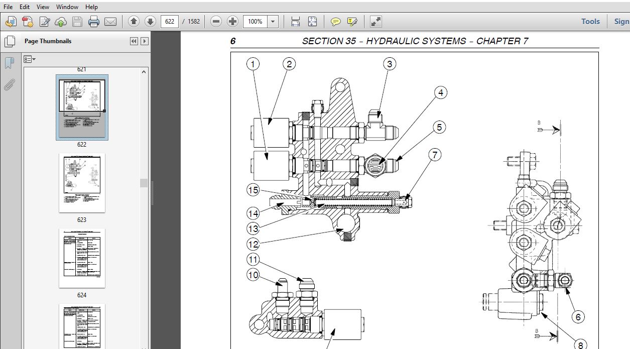
SECTION 35 — HYDRAULIC SYSTEMS
BOOK 3 – 87580877
Chapter 7 — Low-Pressure Hydraulic System Overhaul
CONTENTS
Operation Description Page
Specifications 2
Sectional Views 5
Troubleshooting 8
Overhaul 12
23 202 20 Services Control Valve 12
Removal 12
Disassembly 14
Assembly 16
Installation 16
22
SECTION 35 — HYDRAULIC SYSTEMS
BOOK 3 – 87580877
Chapter 8 — Hydraulic System Testing
CONTENTS
Operation Description Page
Precautionary Statements 2
Special Tools 3
Test Procedures 6
Dual Command Clutch Pack Operating Pressure (Power Shuttle Transmission) 6
Low-pressure System Relief Valve Setting (Power Shuttle Transmission) 6
Low-pressure System Relief Valve Setting (Mechanical Shuttle Transmission) 7
Transmission Lubrication Relief Valve Setting (Power Shuttle Transmission) 8
Transmission Lubrication Relief Valve Setting (Mechanical Shuttle Transmission) 9
Steering System Relief Valve Setting (FWD or 2WD) 10
Steering System Pump Oil Flow 11
High-pressure System Relief Valve Setting 11
High-Pressure System Pump Oil Flow 12
PTO Clutch Pack Operating Pressure 13
PTO Clutch Brake Operating Pressure 14
PTO Clutch Lubrication Relief Valve Setting (Power Shuttle Transmission) 15
PTO Clutch Lubrication Relief Valve Setting (Mechanical Shuttle Transmission) 16
FWD Disengagement Pressure (Power Shuttle Transmission) 17
FWD Disengagement Pressure (Mechanical Shuttle Transmission) 17
Differential Lock Engagement Pressure (Power Shuttle Transmission) 18
Differential Lock Engagement Pressure (Mechanical Shuttle Transmission) 18
23
SECTION 35 — HYDRAULIC SYSTEMS
BOOK 3 – 87580877
Chapter 9 — Walvoil Open-Center Mid-Mount Control Valves
(For Models with Serial Number HJS026057 and Above)
CONTENTS
Operation Description Page
Specifications 2
Tightening Torques 3
Sectional Views 4
Walvoil Mid-mount Valve Stack 4
Walvoil Mid-mount Components 5
Description of Operation 6
Joystick Control 6
Regenerative Lock-out Function 8
Control Valve Circuit 9
Hydraulic Diagram 10
2nd Control Valve 11
Operation in the Neutral Phase (Figure 11) 12
1st Control Valve 13
Operation in the Neutral Phase (Figure 12) 14
1st and 2nd Control Valves 15
Operation in the Neutral Phase (Figure 13) 16
1st Control Valve Operation 17
Lowering Phase 17
Float Phase 17
Lifting Phase 17
2nd Control Valve Operation 18
Lifting Phase 18
Regenerative Phase 18
Lowering Phase 18
1st and 2nd Control Valve Operation 19
24
SECTION 41 — STEERING
BOOK 4 – 87580878
Chapter 1 — Hydrostatic Power Steering
CONTENTS
Operation Description Page
Specifications 2
Tightening Torques 4
Troubleshooting 5
Special Tools 6
Component List 7
Description and Operation 8
Hydrostatic Power Steering (2WD) 8
Hydrostatic Power Steering (FWD) 10
Operation 12
Steering Right 12
Steering Left 12
Manual Steering to Right 12
Manual Steering to Left 12
Overhaul 13
41 204 30 Power Steering Control Valve 13
Removal 13
Installation 17
41 204 34 Disassembly 18
Assembly 23
41 216 10 Power Steering Cylinder(s) (FWD) 32
Removal 32
Installation 32
41 216 20 Power Steering Cylinder (2WD) 33
Removal 33
Installation 34
41 206 10 Power Steering Pump 35
Disassembly 35
Assembly 35
Testing the Steering System 36
Steering Control Valve 36
Checking Rotating Valve Wear 36
Checking Control Valve Return to Neutral 37
Checking the Seals for Leaks 37
Pressure Relief Valve 37
25
SECTION 44 — AXLES AND WHEELS
BOOK 4 – 87580878
Chapter 1 — Axles and Wheels
CONTENTS
Operation Description Page
Specifications 2
Description and Operation 4
Cross-Sectional Views 4
Tightening Torques 5
Special Tools 6
Troubleshooting 6
Overhaul 7
44 101 22 Front Axle Hub 7
Removal 7
Installation 9
44 101 30 Front Axle 10
Removal 10
Installation 12
44 101 46 Stub Axle 13
Removal 13
Installation 15
44 511 80 Adjustments 16
Checking Front Wheel Toe-In 16
Checking FWD Front Wheel Toe-In 17
26
SECTION 50 — AUXILIARY UNITS
BOOK 4 – 87580878
Chapter 1 — Auxiliary Units
CONTENTS
Operation Description Page
Safety Precautions 3
Specifications 4
Special Tools 5
Description and Operation 6
Main Components 8
Sanden SD 7H15 Model Compressor 8
Condenser 9
Filter/Dryer 9
Thermostatic Expansion Valve 10
Electronic Thermostatic Switch (Antifrost) 11
Evaporator 12
Warnings for Air Conditioning System Repair Operations 12
Cab Heating and Ventilation Controls 13
Ventilation 13
Electric Fan 13
Air Filter 13
Temperature Control Knob 14
Ignition Switch 14
Cab Air Conditioning Controls 15
Temperature Control Knob 15
Electric Fan Control Knob 15
Operation 16
Recovery, Recycling, Evacuation, Charging Station (380000315) 16
Description 16
Leak Detector (380000314) 17
Description and Operation 17
Maintenance 17
Air Conditioning System Maintenance 18
Compressor 18
Condenser 18
Filter/Dryer 18
Expansion Valve 18
27
SECTION 50 — AUXILIARY UNITS
BOOK 4 – 87580878
Chapter 1 — Auxiliary Units (Continued)
CONTENTS
Operation Description Page
Troubleshooting 19
Visual Inspection of Components 19
Problems and Possible Causes 20
Functional Tests 24
Checking Air Temperature 24
Checking for Gas Leaks (with Detector 38000314) 25
50 200 10 Compressor Drive Belt 26
Compressor Drive Belt Tension 26
Inspecting the Belt 26
Overhaul 27
50 200 26 Air Conditioner Compressor 27
Removal 27
Installation 29
Compressor Oil — Type and Quantity 29
50 200 40 Heating Pipes 30
Removal 30
Installation 31
50 200 60 Air Conditioner Pipes 32
Removal 32
Installation 37
50 200 72 Air Conditioner Condenser 38
Removal 38
Installation 38
50 200 74 Filter/Dryer 39
Removal 39
Installation 40
50 206 50 Cab Heating Unit 41
Removal 41
Installation 43
50 206 56 Air Conditioner Evaporator 44
Removal 44
Installation 46
50 206 66 Electric Fan 47
Removal 47
Installation 48
28
SECTION 55 — ELECTRICAL SYSTEMS
BOOK 4 – 87580878
Chapter 1 — Instruments
CONTENTS
Section Description Page
55418 Control panel 2
Indicator Lights 2
Analog/Digital Instruments 4
Instruments 4
Liquid Crystal Displays 5
Central Display 6
Advanced Keypad 10
Transmitters, Sensors and Switches 12
Maintenance 20
29
SECTION 55 — ELECTRICAL SYSTEMS
BOOK 4 – 87580878
Chapter 2 — Components
CONTENTS
Section Description Page
General Information 2
Description and Operation 2
Dashboard Controls 2
Lights/horn Switch 3
Direction Indicators 3
Tail/Side Lights, Full Beam, Dipped Beam And Front Headlight Flash 3
Horn 3
Flashing Hazard Warning Lights Switch 4
Swivel Work Lights Switch 4
Differential Lock Switch 4
Four-wheel Drive Switch (version without cab) 5
Starter Switch 5
Advanced Keypad 6
Instrument Calibration Switch (version without advanced keypad) 8
Front Windscreen Washer/Wiper Control Lever (models without cab) 8
Right-hand Mudguard Controls (With Cab) 9
LIFT-O-MATIC Control Button 9
Gear Lever with Dual Command Push-buttons 9
Right-hand Mudguard Controls (Without Cab) 10
Controls on Right-hand Cab Upright 10
Lighting Control Switches 10
Rear Work Lights Control Switch 10
Windscreen Wiper/Washer Switch 11
Electrohydraulic PTO Control Switch (version with cab) 11
Rotating Beacon Light ON/OFF Switch 11
Front Work Lights Control Switch 11
Air Conditioning and Temperature Control 12
Air Conditioning Control Knob 12
Temperature Control Knob 12
Electric Fan Control Knob 12
Bulb Replacement 13
Front Work Lights Lamp 13
Front Sidelight and Direction Indicator Lamp 13
Work Lights Lamp Bulb 14
Front Side Light, Brake and Direction Indicator Lamp 14
30
SECTION 55 — ELECTRICAL SYSTEMS
BOOK 4 – 87580878
Chapter 3 — Starting System
CONTENTS
Section Description Page
Specifications 2
Tightening Torques 2
Description and Operation 2
Fault Diagnosis 6
System Testing 7
Starting System Circuit Resistance (Voltage Drop) 8
Overhaul 9
Starter Motor 9
Removal 9
Installation 9
Disassembly 10
Assembly 11
Testing 12
31
SECTION 55 — ELECTRICAL SYSTEMS
BOOK 4 – 87580878
Chapter 4 — Charging System
CONTENTS
Section Description Page
Specifications 2
Tightening Torques 2
Description and Operation 2
Charging System Testing 4
Precautions 4
Preliminary Checks 4
Battery Check 4
Driving Belt Check 5
Checking the Warning Lights on the Control Panel 5
Tests 5
Alternator Wire Connection 6
Charging Current and Regulated Voltage 6
Charging Circuit Voltage Drop 7
Maximum Alternator Output 8
Alternator Component Tests 9
Overhaul 10
Alternator 10
Removal 10
Disassembly 15
Assembly 17
Installation 18
32
SECTION 55 — ELECTRICAL SYSTEMS
BOOK 4 – 87580878
Chapter 5 — Battery
CONTENTS
Section Description Page
Specifications 2
Description and operation 2
Overhaul 3
Battery 3
Removal 3
Installation 4
Battery Testing 5
Relative Density 5
Battery Maintenance 5
Dry-Charged Batteries 6
Charging the Battery 6
Tests 7
Battery Problems — Causes 9
33
SECTION 55 — ELECTRICAL SYSTEMS
BOOK 5 – 87053395
Chapter 6 — Electrical Circuits
CONTENTS
Section Description Page
Description and Operation 3
Fuse and Relay Layout 3
Standard Deluxe with Mechanical Shuttle Transmission/Without Cab 3
Deluxe with Power Shuttle Transmission/Without Cab 11
Standard/Deluxe with Mechanical Shuttle Transmission/With Cab 15
Deluxe with Power Shuttle Transmission/With Cab 19
Power Sockets 23
Operator Safety Circuit 24
Grid Heater Relay 25
Grid Heater Control Module 25
Electronic Flasher Module 25
Ground Location Points 26
Symbols Used In Electrical Circuits 28
Wire Color Coding 29
Electrical Circuits 30
34
SECTION 55 — ELECTRICAL SYSTEMS
BOOK 5 – 87053395
Chapter 7 — Components Testing
CONTENTS
Operation Description Page
Components 2
Differential Lock Indicator Switch (66) 2
Brake Fluid Level Switch (18) 3
Low Transmission Oil Pressure Switch (83) 3
Air Filter Clogged Switch (12) 3
Lift Status Switch (127) 3
Fuel Sediment Filter Switch (4) 4
Engine Coolant Temperature Sensor (2) 5
Brake Light Switch (16) 5
Safety Pressure Switches / Italia Trailer Brake Valve Circuit Indicator (54) 5
Handbrake Status Switch (25) 6
Dual Command (2 Speed Power Shift) Switches (76) 7
Gear/Range Lever Position Sensors (139–140–141) 8
Alternator (87) 9
Engine Oil Pressure Sensor (82) 10
Speed Sensors (68–162) 10
Speed Sensor for Electronic Lift (162) 10
Power Shuttle Control Unit Ground Speed Sensor (68) 10
Switch (126) and Clutch Pedal Potentiometer (129) 11
Power Shuttle A/B Clutch Pressure Switches (132–133) and Oil Temperature
Sensor (138) 12
Power Shuttle Lever (130) 13
Radar (123) 14
Fuel Level Indicator (67) 14
4WD Pressure Switch (70) 14
PTO Speed Sensor (62) 15
Seat Safety Switch (97) 16
Electronic Lift Arm Position Potentiometer (145) 16
Draft Pin Sensors (119–120) 16
Overhaul 17
55 518 52 Front Wiper Motor 17
Removal 17
Installation 17
35
SECTION 55 — ELECTRICAL SYSTEMS
BOOK 6 – 87053396
Chapter 8 — Fault Codes
CONTENTS
Operation Description Page
Introduction 2
Special Tools 3
Wiring Harness Repairs 3
Temporary Wiring Harness Repair 3
Harness Wire Replacement 5
Testing 6
Digital Multi-Meter 6
Electrical Tests 9
Continuity Test – Short to Ground 9
Voltage Measurement or Short to Positive Supply Volts 10
Resistance Test for Electrical Parts 10
Continuity Test – Check for Open Circuits 11
Circuit Components 12
Circuit Protection Devices 12
Fuses 12
Fuse Links 12
Circuit Control Devices 13
Switches 13
Flashers 14
Diodes 14
Resistance Devices 14
Potentiometers 14
Electromagnetic Devices 15
Relays 15
Solenoids 16
PWM Solenoid Valves 17
Sensors 19
Electronic Modules 21
Controller Area Network (CAN) System 22
Controller Locations 22
Fault Code Displays 23
H-Menu Diagnostic Mode 25
36
SECTION 55 — ELECTRICAL SYSTEMS
BOOK 6 – 87053396
Chapter 8 — Fault Codes (Continued)
CONTENTS
Operation Description Page
Error Code Listing 26
Transmission 26
Rear Power Take-Off (PTO) 28
Four Wheel Drive (FWD) 29
Differential Lock 30
Analogue Digital Instrument Cluster (ADIC) 31
Electronic Draft Control (EDC) not in North America 32
Calibration U-Codes 33
Transmission Error Code Listing 37
Rear Power Take-Off (PTO) Error Code Listing 239
Four Wheel Drive Error Code Listing 257
Differential Lock Error Code Listing 267
Analogue Digital Instrument Cluster (ADIC) Error Code Listing 281
Electronic Draft Control (EDC) Error Code Listing 349
SECTION 55 — ELECTRICAL SYSTEMS
BOOK 7 – 87053397
Chapter 9 — HH Menu and Calibrations
CONTENTS
Section Description Page
Description and Operation 2
Instrument Panel Display 2
Calibrations 2
HH MENU Access 3
HH MENU of the Instrument Panel 4
HH MENU of the Dual Command Power Shuttle Transmission (PA) 11
HH MENU of the Advanced Keypad (JB) 24
37
SECTION 55 — ELECTRICAL SYSTEMS
BOOK 7 – 87053397
Chapter 10 — CAN Bus Network
CONTENTS
Section Description Page
Description and Operation 2
Terminology 2
Troubleshooting 6
Testing 7
Repair 12
SECTION 90 — CAB, PLATFORM, AND BODYWORK
BOOK 7 – 87053397
Chapter 1 — Removal of Components
CONTENTS
Operation Description Page
Special Tools 3
Overhaul 4
90 100 22 Engine Hood 4
Removal 4
Installation 5
90 110 36 Platform 6
Removal 6
Installation 13
90 120 10 Operators Seat 14
Removal 14
Installation 14
90 150 10 Cab 15
Removal 15
Installation 26
90 154 10 Cab Doors 28
Removal 28
Installation 28
38
SECTION 90 — CAB, PLATFORM, AND BODYWORK
BOOK 7 – 87053397
Chapter 1 — Removal of Components (Continued)
CONTENTS
Operation Description Page
90 156 10 Cab Windows (Glued) 29
Removal 29
Installation 30
90 156 52 Cab Rear Window 31
Removal 31
Installation 33
90 160 16 Left-Hand Pillar Seal 34
Removal 34
Installation 34
90 160 16 Right-Hand Pillar Seal 35
Removal 35
Installation 36
90 160 42 Right-Hand Wall Padding 37
Removal 37
Installation 39
90 160 43 Left-Hand Wall Padding 40
Removal 40
Installation 41
90 160 50 Hydraulic Control Lever Guard 42
Removal 42
Installation 43
90 160 60 Cab Ceiling Trim 44
Removal 44
VIDEO PREVIEW OF THE MANUAL:
IMAGES PREVIEW OF THE MANUAL:

More products